
Bell T17C 6X4 Tip Deck Parts Manual 872006-01 PDF Download
Original price was: $29.95.$17.95Current price is: $17.95.
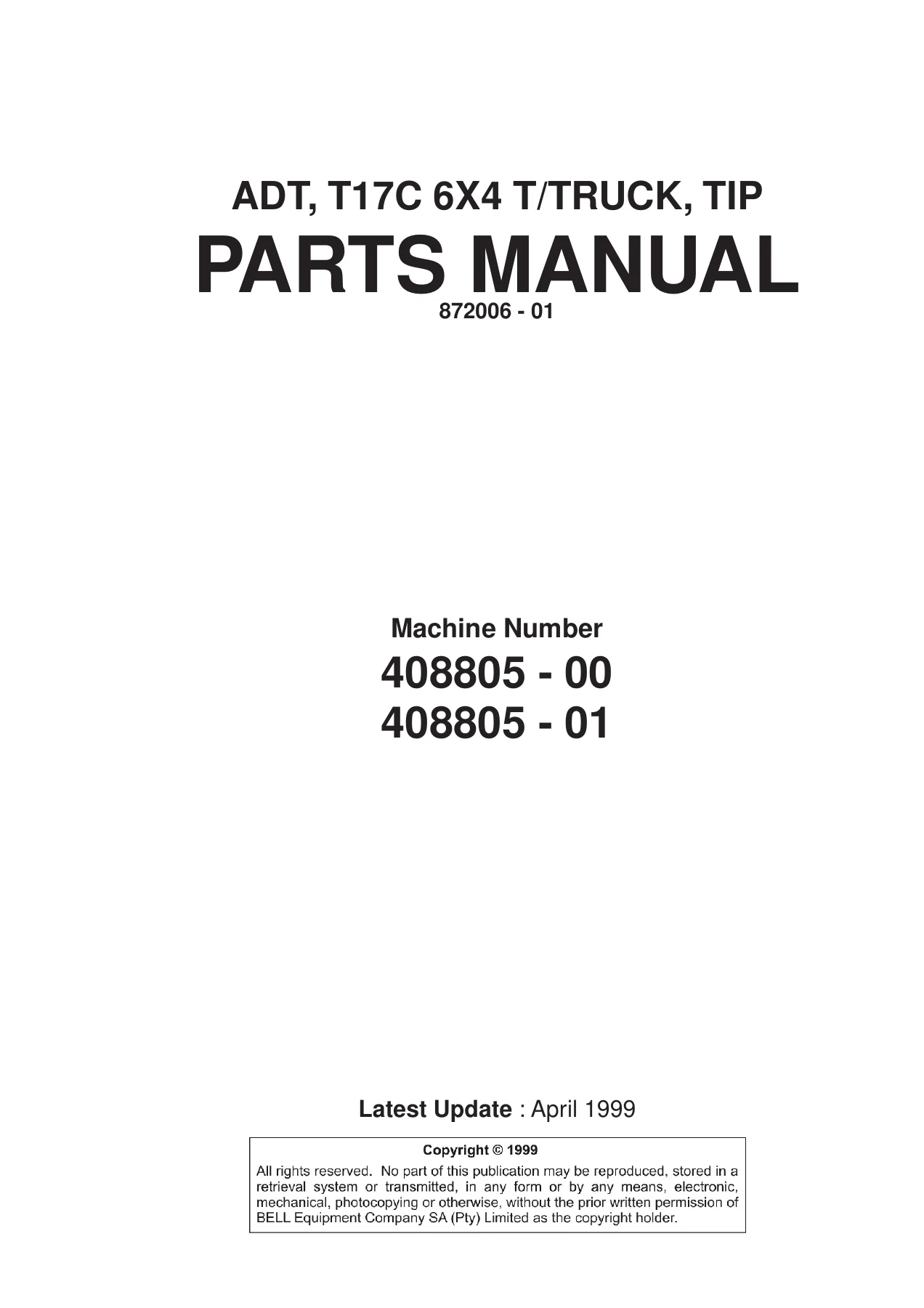
Illustrated BELL parts manual for the T17C (6X4) Tip Deck, document 872006-01, covering machine numbers 408805-00 and 408805-01. 350 pages of exploded assembly views and matching part number lists across engine, powertrain, hydraulics, pneumatics, electrics, frame and body.
Description
BELL T17C (6X4) Tip Deck Parts Manual – Document 872006-01
This illustrated parts manual covers the BELL T17C (6X4) Tip Deck articulated dump truck under document number 872006-01, for machine numbers 408805-00 and 408805-01. Every major assembly in the machine is broken down into exploded illustrations supported by a matching parts list, so a component can be identified visually and ordered by its BELL part number. The manual carries a latest update of April 1999 and runs to 350 pages of parts breakdowns, circuit schematics and specification plate references.
File Details
- Manual type: Illustrated parts manual (parts catalogue)
- Brand: BELL Equipment
- Model: T17C (6X4) Tip Deck
- Machine numbers covered: 408805-00, 408805-01
- Document number: 872006-01
- Latest update: April 1999
- Language: English
- Page count: 350
- File format: PDF
Chapters Covered
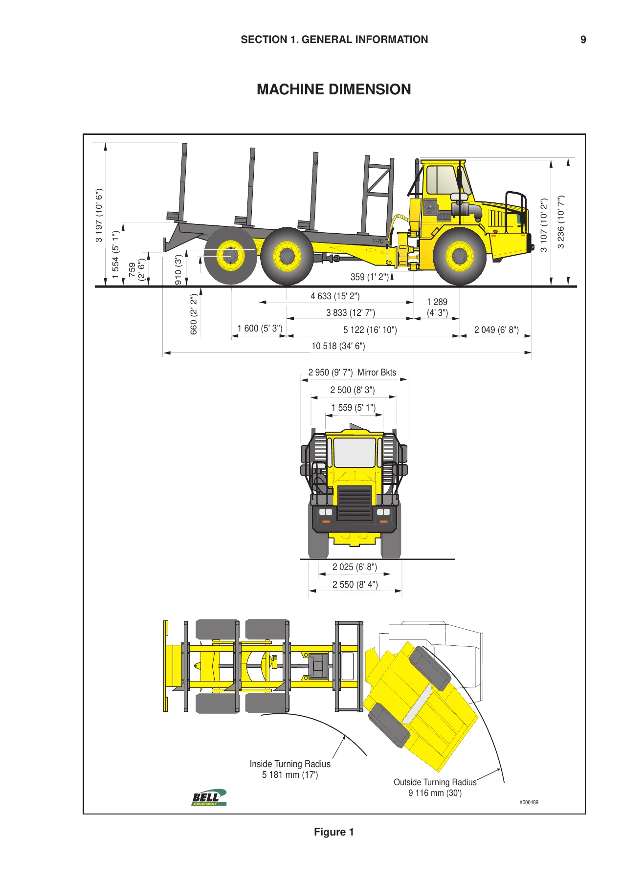
- Section 1 – General Information: Introduction and how to use the manual, BELL branch and dealer address listings, user comment form, technical documentation bulletin record pages, ordering information and the list of abbreviations.
- Section 2 – Engine:
- Engine and miscellaneous parts
- Engine and miscellaneous parts (Revision 01)
- Engine connection kit
- Air cleaner system
- Air cleaner
- Pre cleaner
- Exhaust system
- Fuel system
- Throttle to engine linkage
- Throttle to engine linkage (Revision 01)
- Throttle position sensor linkage
- Engine shutdown solenoid
- Engine cooling package
- Engine cooling package (Revision 01)
- Engine cooling system
- Air cooler system
- Air cooler system (Revision 01)
- Fan guard kit (optional)
- Section 3 – Power Train:
- Transmission and miscellaneous parts
- PTO Model 266
- Transmission cooling system
- Transfercase miscellaneous parts
- Transfercase assembly, input and output flange variants
- Park brake assembly
- Propshaft sections
- Driveline and driveline (Revision 01)
- Retarder and retarder assembly
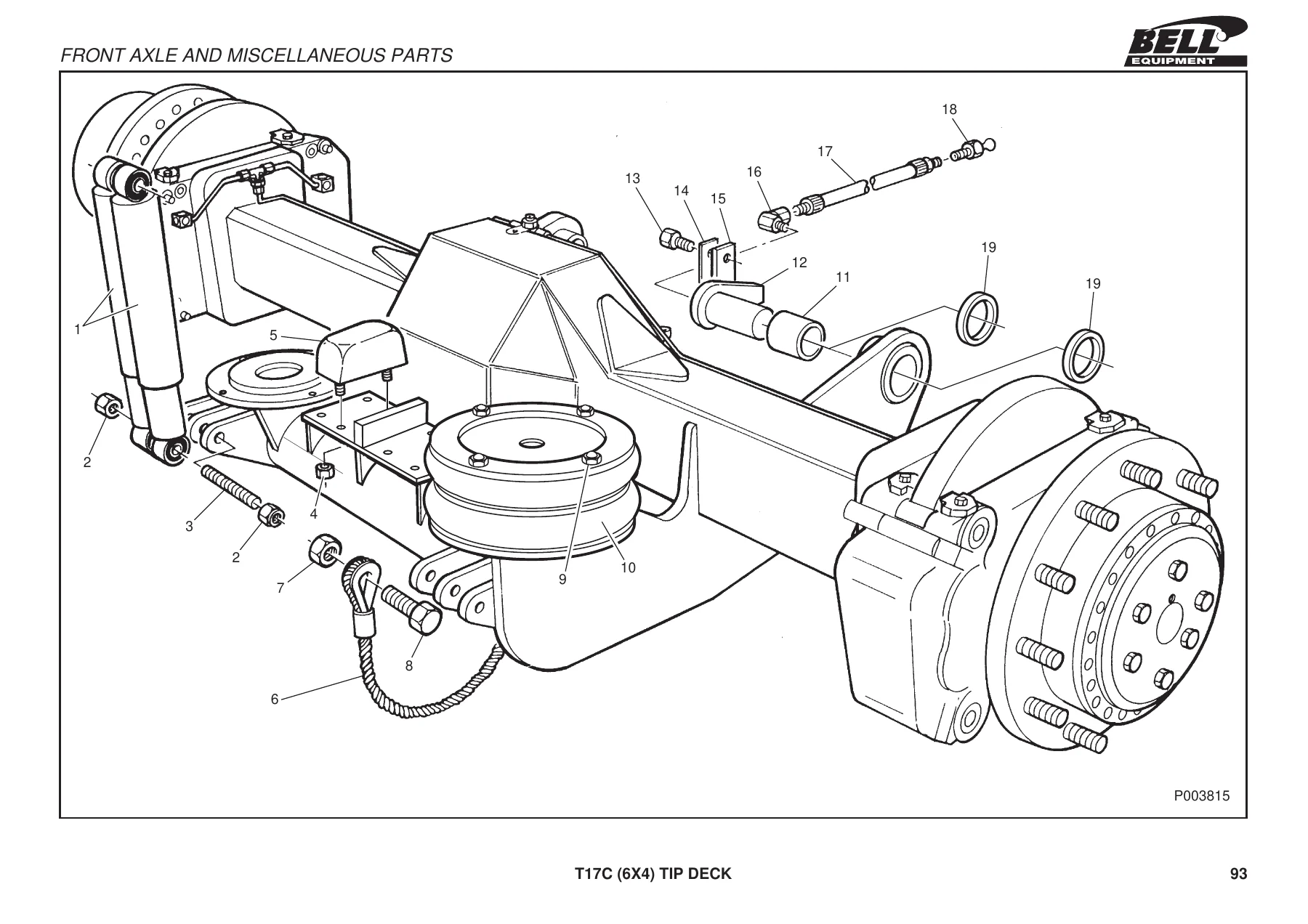
- Front axle and miscellaneous parts
- Front axle assembly
- Differential assembly
- Rear and middle axle mountings
- Middle axle assembly
- Trailing axle assembly
- Hub assembly
- Brake assembly
- Section 4 – Hydraulics:
- Hydraulic tank
- Hydraulic filter assembly
- Hydraulic block – front view
- Hydraulic block – front view (Revision 01)
- Check valve block
- Rotation pump
- Service pump
- Steering valve
- Foot brake valve
- Steering cylinder (RHS)
- Steering cylinder (LHS)
- Tip cylinder
- Section 5 – Pneumatics:
- Pneumatic system (front)
- Pneumatic system – front (Revision 01)
- Pneumatic system (rear)
- Air spring assembly
- Solenoid valve
- Park brake
- Levelling valve
- Double check valve
- Tip lever
- Unloader valve with integral air drier assembly
- Tyre inflation kit (optional)
- Air horn kit (optional)
- Section 6 – Electrics:
- Starting charging circuit schematic
- Warning lights circuit
- ADT MFA 10 and overrev circuit
- Headlight schematic
- ADT indicator and hazard circuit schematic
- ADT reverse and stop lights and horn circuit
- ADT aircon and blower circuit
- ADT blower and wiper circuit (standard)
- ADT cold start, rotating beacon and cigarette lighter circuit
- ADT radio cassette player (optional)
- ADT bin, gear hold and exhaust brake circuit
- ADT Allison transmission WTEC 3 Ver 8 circuit
- ADT connectors 1 and 2
- Center console, right hand side console, airconditioner control unit, shift tower
- Battery clamps and cables, circuit breaker box, horn assembly
- Section 7 – Frame and Body:
- Bonnet assembly and bonnet assembly (Revision 01)
- Bonnet latch assembly
- Cab assembly and cab mountings
- Cab mirrors
- Cab door and door handle assembly
- Cab windows
- Cab wiper and motor
- Cab reservoir
- Cab floors
- Cab interior trim
- Cab seats and seat assembly
- Cab instrument panels
- Cab steering column
- Cab lights and cab miscellaneous
- Airconditioner layout, blower layout, condenser assembly, blower assembly
- Front chassis, light mounting RHS and LHS
- Rear chassis
- Fuel tank and battery box
- Articulation and oscillation assembly
- Steering cylinder mountings and tip cylinder mountings
- Decals, warning triangle and belly plate kit (optional)
Read as a whole, this parts manual is a complete component-level map of the T17C (6X4) Tip Deck. The engine section alone works through the engine mounting group, oil separator and cylinder head cover, fuel and oil filter bowls, fan and fan coupling, V-belt, the engine connection kit with flex plates and adaptor ring, and then the complete air cleaner, exhaust and fuel system groups with their pipework, silencer mountings, heat shields and exhaust brake components. Powertrain coverage extends from the transmission mounting group and PTO Model 266 through the transfercase input and output flange assemblies, the clutch and gear internals of the 7C output flange, the park brake actuator and disc, every propshaft and universal joint assembly, the driveline oscillation shaft, the retarder, the front axle assembly with its calipers and side shafts, the limited slip differential assemblies with their clutch disc and spacer options, the middle and trailing axle assemblies, the hub assemblies with sun, planet and ring gears, and the brake caliper assembly with piston, seal and pad parts.
Hydraulics are documented at the same level of detail: the hydraulic tank with level indicator, filler cap, lid and strainer, the filter assembly, the front hydraulic manifold blocks in both original and Revision 01 form with their check valves, pressure relief valves, pressure reducing valves, directional control valve, shuttle seats, spool housings, springs, seals and orifices, the check valve block, the rotation and service pumps with their pistons, cylinder, drive shaft, swash plate and distribution plate parts, the steering valve with gerotor, spool and centering spring, the brake pedal valve assembly, and both steering cylinders and the tip cylinder with every seal, wiper, O-ring, piston, rod, neck bush, spherical bearing and circlip.
The pneumatics section is unusually thorough for a parts book, presenting full front and rear system schematics as well as individual components – air spring assemblies, solenoid valves, park brake valve with its complete repair kit breakdown, levelling valve, double check valve, tip lever assembly with its seal and spring pack kits, the unloader valve with integral air drier, and the optional tyre inflation and air horn kits with their fittings, tubing and solenoid mounting.
Electrics are covered through full circuit schematics rather than plain text: starting and charging, warning lights, MFA 10 master instrument and overrev, headlight, indicator and hazard, reverse, stop lights and horn, aircon and blower, blower and wiper, cold start with rotating beacon and cigarette lighter, the optional radio cassette converter, bin and gear hold with exhaust brake, and the Allison WTEC 3 Ver 8 transmission circuit. Supporting hardware is listed too, including the centre and right hand consoles, airconditioner control unit, shift tower, battery clamps and cables, circuit breaker box and horn assembly.
The final section documents the frame and body: bonnet, hinges and latch mechanism, cab mountings, mirrors, door, handle, windows, wiper motor, reservoir, floor plates, interior trim, seats, instrument panels and steering column, interior lighting, airconditioner and blower layouts, condenser and blower assemblies, front and rear chassis, fuel tank, battery box, articulation and oscillation joint assemblies, steering and tip cylinder mountings, the decal set with its greasing point and warning decals, and the optional belly plate kit.
How to Find and Order the Right Part
Each illustrated breakdown in the BELL T17C parts manual is numbered, and the numbers on the drawing correspond directly to the item column of the parts list underneath it. That means you can trace a part from the picture to its BELL part number without dismantling anything to measure it first. The parts lists also give quantity per assembly and, where relevant, remarks such as which items are included in a kit, which are part of a larger assembly, which are service options such as spacer disc thicknesses, and which are marked as not included in the main axle or assembly part number.
Revision 01 pages are provided alongside the original listings for several groups – engine and miscellaneous parts, throttle linkage, cooling package, air cooler system, hydraulic block, driveline, rear and middle axle mountings, bonnet, instrument panels, cab miscellaneous, articulation and oscillation, and tip cylinder mountings. Where a machine has been through a revision, this lets you match the correct version to your machine rather than ordering a superseded item.
What This Parts Manual Lets You Do
With this manual in hand you can identify any assembly on the BELL T17C (6X4) Tip Deck, break it down to individual components, and order exactly what is needed rather than a complete assembly. That is the difference between a straightforward repair and an expensive guess: the correct part number, the correct quantity, and the correct seal, shim or spacer option the first time. It is equally useful for rebuilding a differential to the right clutch disc and spacer combination, replacing a steering or tip cylinder seal kit by part number, tracing a pneumatic or electrical fault through the schematic before touching a hose or a loom, and checking which items come in a kit so you do not buy separately what is already supplied together.
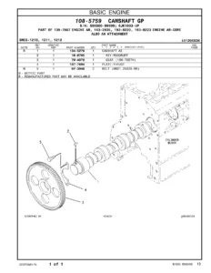
IMAGES PREVIEW
Ordering is instant. This is a PDF parts manual delivered as a download the moment payment clears – no shipping, no waiting, no printed binder to lose in the workshop. Read it on a laptop, tablet or phone, search a part number, zoom into an exploded view for detail, and print just the pages you need to take out to the machine. Because the file stays on your device, the same copy keeps working for every service, every rebuild and every future parts order for machine numbers 408805-00 and 408805-01.
Reviews
There are no reviews yet.