
Benelli 502C Euro IV Service Manual – Complete Workshop Repair Guide PDF
Original price was: $34.95.$19.95Current price is: $19.95.
Full 387-page service manual for the Benelli 502C Euro IV. Engine, frame, brakes, ABS, suspension, electrical system, wiring diagram, periodic maintenance and torque specs.
Description
Benelli 502C Euro IV Service Manual — Complete Workshop Repair Guide
This is the complete service manual for the Benelli 502C Euro IV motorcycle. Whether you are a professional technician or a dedicated owner performing your own maintenance, this Benelli 502C Euro IV service manual provides the full range of procedures, specifications, and reference data needed to keep the machine in correct working order. It covers the 499.6 cc parallel-twin engine, the trellis frame, braking and ABS systems, suspension, electrical architecture, and every major assembly of the motorcycle.
File Details
- Manual type: Service / Workshop Manual
- Brand: Benelli
- Model: 502C
- Language: English
- Page count: 387 pages
- File format: PDF
Chapters Covered
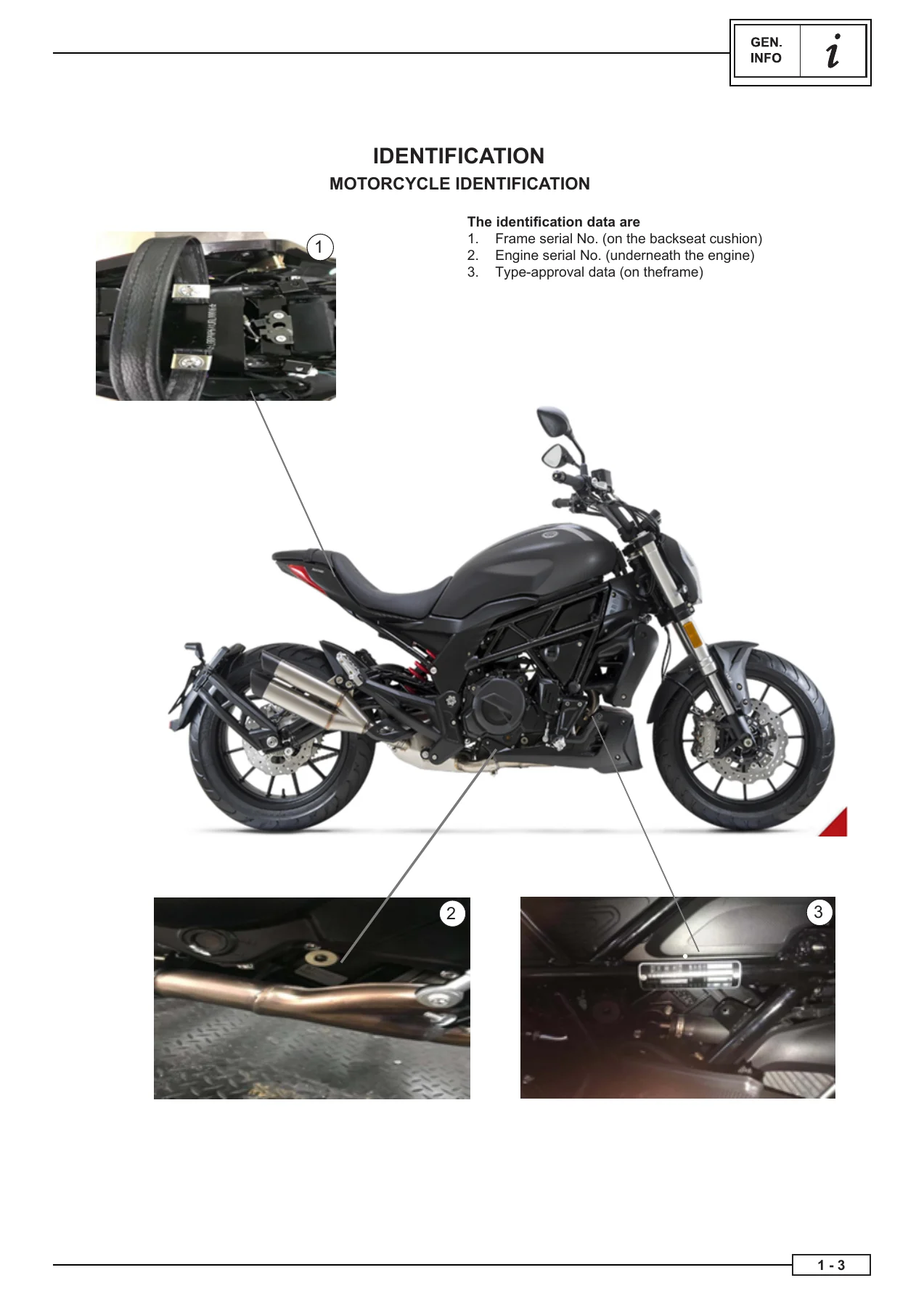
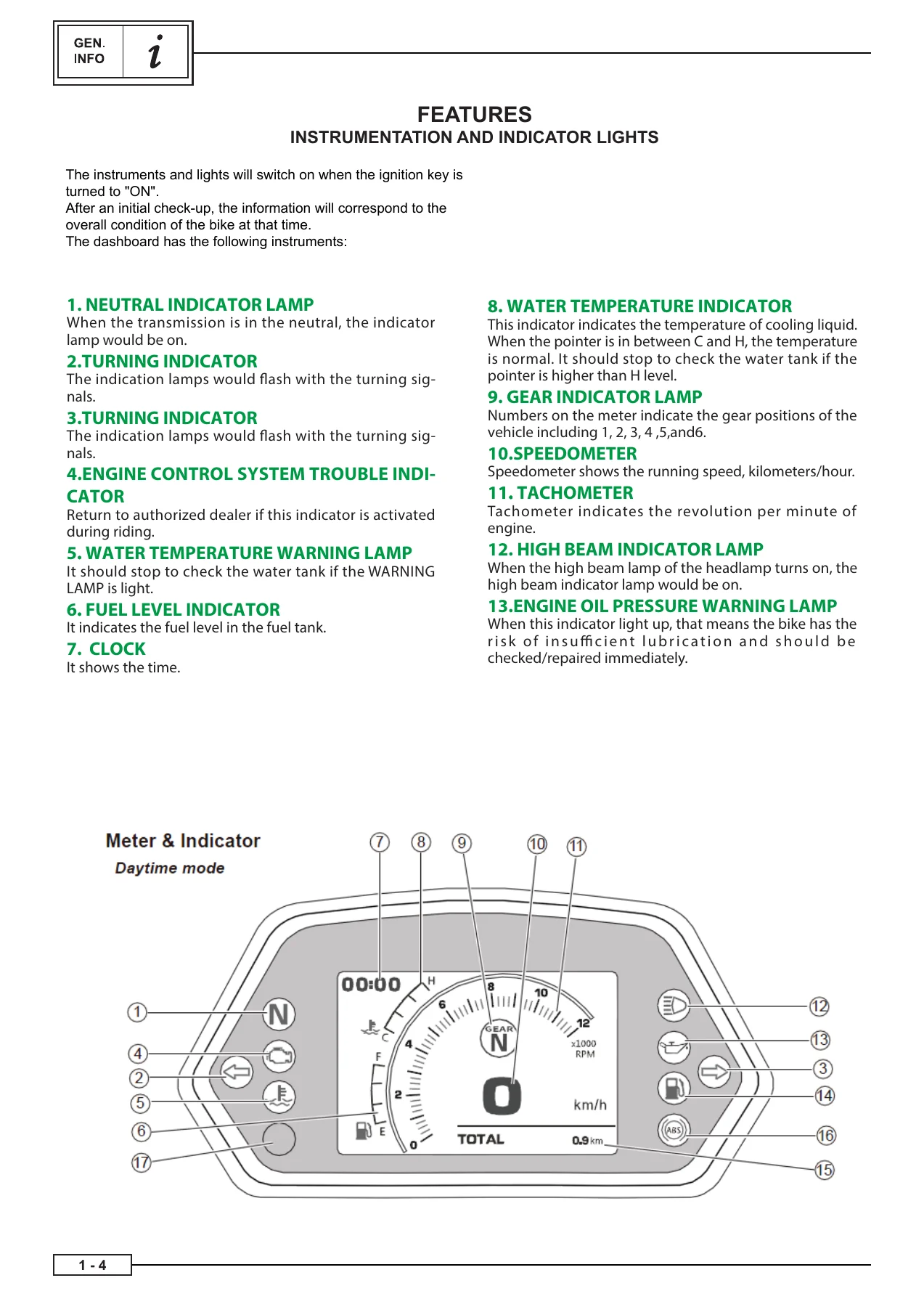
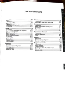
- Chapter 1 — General Information: Frame serial number location, engine serial number location, type-approval data, instrumentation and indicator lights (neutral, turn signals, engine control system trouble, water temperature warning, fuel level, clock, gear indicator, speedometer, tachometer, high beam, engine oil pressure warning, fuel level warning, odometer/trip meter, ABS indicator), important information, getting ready for removal and disassembly operations, spare parts, gaskets, O-ring, oil seals and bearings, safety washers/plates, cotter pins and thread sealant, safety snap rings, checking connections, special tools.
- Chapter 2 — Specifications: General specifications, technical data, engine specifications (engine type, cubic capacity, cylinder layout, bore × stroke, compression ratio, idle speed, distribution, maximum net power, max net torque, fuel, engine oil, oil filter, oil pump, starting, spark plugs, cylinder head, camshafts, valves, valve seats, valve guides, valve spring, cylinders, piston, connecting rods, drive shaft, clutch, transmission, gear shift mechanism, air filter, fuel pump, throttle body), frame specifications (frame, front wheel, rear wheel, front tyre, rear tyre, front brake, rear brake, front suspension, steering, rear suspension, transmission chain), electrical specifications (system voltage, ignition coils, recharge system, ignition relay, battery, headlamp, bulbs, electric ignition system, horn, flasher relay, oil pressure sensor, fuses, throttle valve sensor, fuel pump, safety switches, airbox air temperature sensor, throttle body air pressure sensor, liquid temperature sensor, velocity sensor, lambda probe, injector, relay unit, ignition system, stepper, radiator fan), general tightening specifications, tightening torques and relevant preloads for standard connections.
- Chapter 3 — Periodic Maintenance: Periodic maintenance and lubrication intervals, maintenance intervals, engine/air box removal/assembly of air box, engine/throttle cable clearance adjustment, rear-view mirror adjustment, engine/motor oil checking engine oil level, engine oil change, oil filter removal/installation, engine/spark plugs removal, spark plug check, assembly of spark plugs, engine/cooling system checking coolant level, frame/brake adjustment front and rear, frame/checking brake fluid level, checking ABS hoses, frame/brake pad check, checking hoses of the braking system, frame/transmission chain adjustment, lubrication and chain guide check, checking wear of transmission chain, frame/check and adjustment of steering sleeve, check of front fork, check of rear shock absorber, frame/check of front/rear tyres, tyre check, electrical system battery check and charging, fuses, fuse check, removal of the front headlight, adjustment of headlight, substitution of the rear LED light, rear indicator lights, front indicators, ignition block.
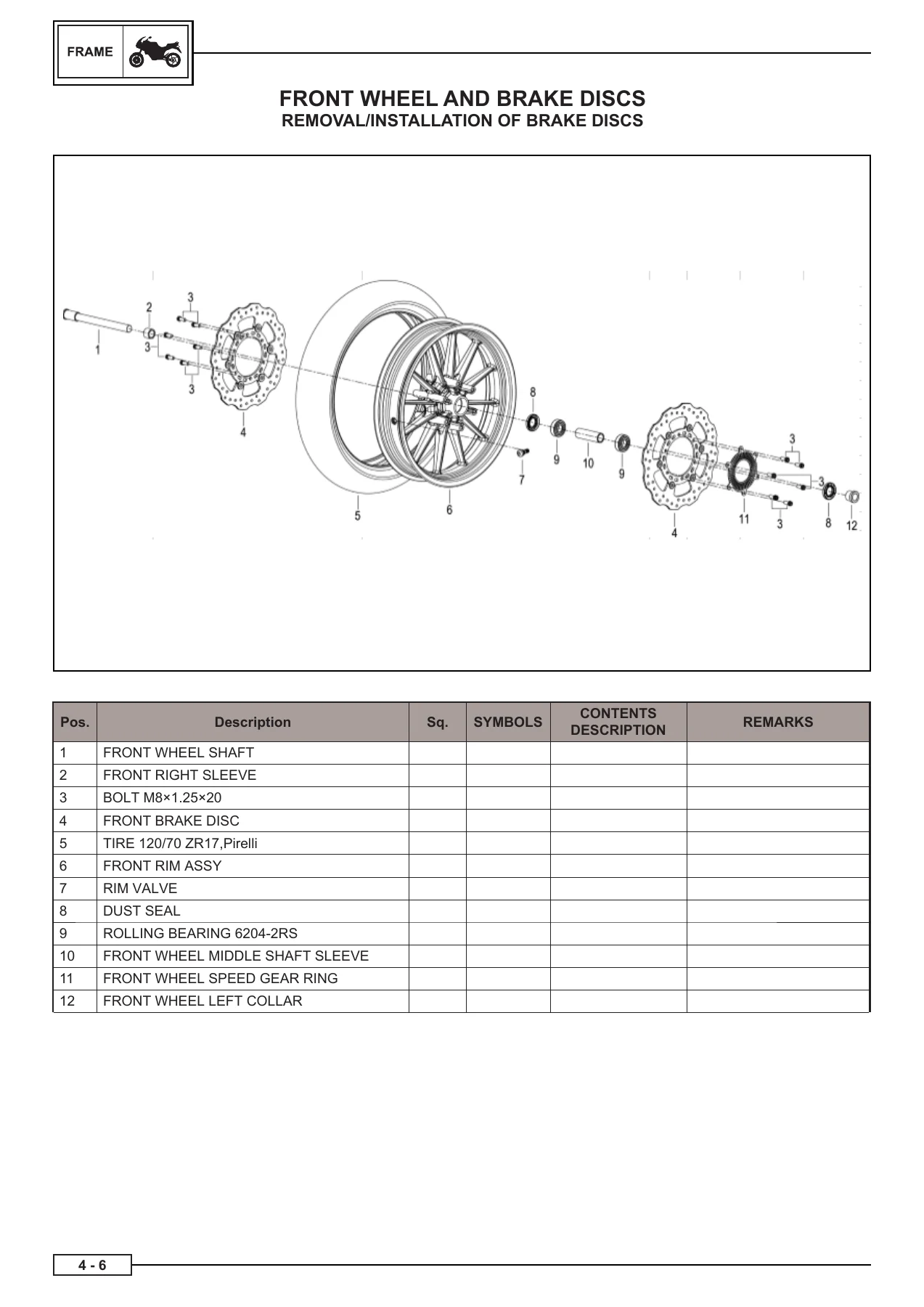
- Chapter 4 — Frame: Front wheel removal, removal/installation of brake discs, check of brake discs, wheel axle check, check/replacement of wheel bearings, front wheel installation, rear wheel and brake disc removal, removal of the rear disc brake, crown wheel and phonic wheel, wheel axle check, sprocket check and replacement, installation of the disc brake, back tyre installation, front and rear brakes removal and installation of front/rear brake pads, front brake pump removal, rear brake pump removal, front brake pump installation, rear brake pump installation, ABS anti-lock braking system location of components, rotation sensor check, check of the phonic wheel and ABS of the front and rear wheel, precautions, removal of the ABS hydraulic unit, installation of the ABS hydraulic unit, removal of the ABS rotation sensors, front brake calliper tightness, rear brake calliper, check the front and rear callipers, front/rear brake calliper installation, front fork stem removal/disassembly/inspection/assembly/fitting, handlebar removal/inspection/installation, steering head removal of the top and bottom steering base, top and bottom steering base inspection/fitting, rear shock absorber removal/check/fitting, transmission chain removal/replacement, removal of the swinging arm, frame installation/removal of the frame parts, removal of the rear frame, rear frame fitting, rear lower fender & rear turn indicator light, removal/installation of the number plate holder, cycling installation of the stand/footrests, removal/installation of the side stand, removal/installation of the rear footrests support, removal/installation of the right/left rear footrests, right/left front footrest removal/fitting, removal/installation of the gear lever, exhaust system assembly removal/installation, front/rear mud guard removal/installation, removal/installation of the chain cover, removal of fuel tank, installation tank fitting, tank parts, removal/installation of the tank pump, removal/installation of the tank fuel level sensor, air filter removal/installation, installation of the air filter box.
- Chapter 5 — Engine: Head distribution coils and spark plugs removal/assembly, timing gear cover assembly, distribution chain tensioner removal/assembly, intake and exhaust camshaft removal, camshaft check, exhaust/intake camshaft installation, timing chain slide removal/assembly, timing chain removal, distribution chain installation, valve clearance adjustment, camshaft and valve pad removal, head removal, valve flap and spring removal, check of valves and guides, valve seat check, valve oil seal removal/installation, valve spring test, valve and valve spring installation, cylinder check, head installation, pistons piston removal, piston pin check, piston rings check, piston check, piston assembly, piston installation, removal of connecting rods, crankcase check of connecting rod and connecting rod bearing shells, installation of connecting rod and connecting rod bearing shells, main bearing shell and drive shaft installation, drive shaft check/installation, clutch and disc removal, friction disc check, steel disc check, disc assembly, clutch assembly, lubrication system oil sump and intake filter removal/installation, pressure-relief valve installation/removal, oil pump removal/assembly, neutral position/gear indicator sensor removal/assembly, gear box assembly, gear shift control, starter removal/installation, flywheel removal/installation, starter gear removal/assembly, phase sensor removal/installation, power system throttle body, throttle valve removal/installation.
- Chapter 6 — Cooling System: Water pump removal/installation, thermostat removal/installation, water manifold removal/installation, heat exchanger removal/installation, radiator disassembly/installation.
- Chapter 7 — Electrical System: Sensors description of the engine management system, coolant temperature sensor, gear position sensor, phase sensor, air temperature sensor, side stand switch, lambda probe, oil pressure sensor, front brake microswitch, idrostop, clutch switch, MAP sensor, position sensor of the throttle body unit (potentiometer), devices position, right electric device, starting relay, horn, instrumentation dashboard, master switch, voltage regulator, left electric device, converter of CAN bus signals, injection ECU, injection ECU connections, indicator light intermittence, services relay, stator, actuators position, idle air control system (stepper), injectors, ignition coils, cooling fan, fuel pump, fuel level sensor, starter, ABS ECU, battery, vehicle battery, battery efficiency control, diagnostics, vehicle diagnostics, wiring diagram of 502C electrical system, colour key.
This Benelli 502C Euro IV service manual is structured for practical use in the workshop. Each chapter is divided into sections, and every removal or disassembly procedure begins with exploded drawings and a table listing the order of operations, part names, and relevant notes. Lubrication and replacement points are marked with symbols, and procedures requiring special tools or additional technical information are described in sequence. The document also includes a dedicated special tools section covering engine-specific tools such as the clutch disassembly wrench, piston pin removal pad, valve oil seal tools, ring clamp tool, gear selector drum assembly tool, flywheel extractor, flywheel cover extractor, engine phasing tool, oil filter tool, chain tensioner lock tool, clutch bell ring nut tool, valve spring compressor, and measuring tools.
The specification chapter delivers the full technical baseline for the 502C, including the 499.6 cc parallel-twin engine with 69 mm bore and 66.8 mm stroke, 11.5:1 compression ratio, 35 kW maximum power at 8500 rpm, and 46 Nm maximum torque at 6000 rpm. Valve clearances, camshaft lobe dimensions, cylinder bore limits, piston clearances, clutch plate thicknesses, transmission ratios, tyre pressures, brake disc thicknesses, suspension travel, fork oil quantity, chain slackness, electrical resistances, battery capacity, fuse ratings, and tightening torques are all listed with the same precision as the factory data. Whether you are checking a clearance, replacing a bearing, bleeding the ABS circuit, adjusting the steering sleeve, or rebuilding the top end, the numbers you need are in this manual.
The electrical chapter goes beyond component replacement. It documents the engine management system, sensor-by-sensor, with resistance values, continuity checks, and operating thresholds. The injection ECU error table lists diagnostic codes for lambda heaters, MAP sensor faults, coolant temperature sensor faults, TPS faults, injector circuits, idle air control, fuel pump relay, canister purge valve, and more. The wiring diagram for the 502C electrical system is included along with a colour key, making circuit tracing and fault finding practical rather than guesswork. For ABS-equipped models, the manual covers the anti-lock braking system components, rotation sensor checks, phonic wheel inspection, hydraulic unit removal and installation, and the precautions that must be observed when servicing the ABS circuit.
The periodic maintenance chapter provides the maintenance intervals and the procedures behind them — engine oil and filter changes, air filter service, spark plug checks, coolant level checks, brake fluid topping up, brake pad inspection, transmission chain adjustment and lubrication, steering clearance checks, front fork and rear shock absorber checks, tyre inspection, battery charging, fuse checks, headlight adjustment, and indicator light replacement. The intervals are laid out in a table that covers the first 1000 km service through to 19,000 km and beyond, with the operations that must be carried out at each stage.
If you own a Benelli 502C Euro IV, this service manual is the reference you keep on the bench. It allows you to carry out routine maintenance correctly, diagnose electrical faults with the ECU error table and wiring diagram, remove and install wheels, brakes, suspension, and steering components, service the cooling system, and rebuild the engine when required. The exploded views, torque values, and step-by-step procedures reduce the risk of damage from incorrect assembly and help ensure the motorcycle is put back together to specification. The PDF is delivered instantly after payment, can be viewed on any device, and can be printed for use in the workshop.
IMAGES PREVIEW


Reviews
There are no reviews yet.