
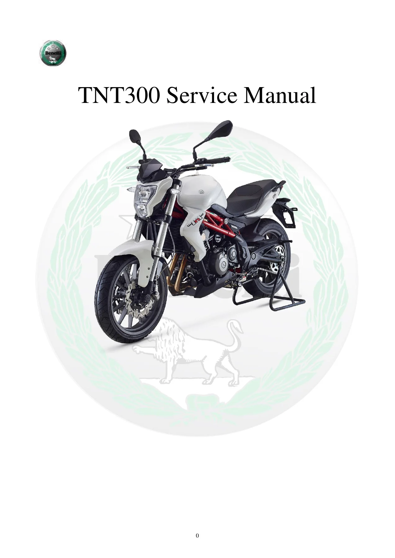
Benelli TNT300 Service Workshop Repair Manual – 488 Page PDF
Original price was: $39.95.$24.95Current price is: $24.95.
Complete 488-page Benelli TNT300 service manual covering scheduled maintenance, chassis repair, engine service, cooling and fuel systems, electrical diagnosis, fuel injection troubleshooting, specifications, tightening torques, special tools, exploded views and circuit diagrams.
Description
Benelli TNT300 Service Workshop Repair Manual – 488 Page PDF
This Benelli TNT300 Service Workshop Repair Manual – 488 Page PDF is a detailed repair and maintenance reference for the TNT300 motorcycle. Prepared for Benelli dealers and professional maintenance personnel, the manual presents component removal, disassembly, inspection, repair, adjustment and assembly procedures in a step-by-step format. It combines routine service information with extensive engine, chassis, fuel-injection and electrical-system procedures, technical data, wear limits, tightening torques and diagnostic guidance.
The manual identifies the TNT300 as using a four-stroke, inline twin-cylinder, water-cooled engine with four valves per cylinder and double overhead camshafts. Its specification section records a total displacement of 299.82CC, a 6-speed constant-mesh transmission, fuel injection, liquid cooling and a 12V electrical system. Throughout the repair chapters, exploded drawings and component illustrations are paired with operating sequences, part identification, precautions, technical parameters and special-tool information.
File Details
- Manual type: Service Manual / Maintenance Manual
- Brand: Benelli
- Model: TNT300
- Language: English
- Page count: 488 pages
- File format: PDF
Specifications and Service Data
A substantial specification section makes the Benelli TNT300 service manual useful before disassembly begins. It provides motorcycle dimensions and weights, engine configuration and performance data, engine-oil specifications and quantities, coolant data, spark-plug information, valve clearances, clutch data, transmission ratios, wheel and tire information, brake specifications, suspension data, drive-chain information and electrical-system values.
Examples recorded in the manual include 299.82CC total displacement, a 65.0 x 45.2 bore and stroke, 12:1 compression ratio, maximum net power of 37.6 HP at 12000 rpm and maximum net torque of 20.21 ft. lbs. at 9000 rpm. The specified engine oil is SAE 10W-40 meeting the listed API/JASO requirements, while the cooling system uses a 50% distilled-water and 50% coolant mixture with a listed total quantity of 2 L. The manual also provides valve-clearance ranges, spark-plug type and gap, clutch specifications, gearbox ratios, fuel-pump data and numerous dimensional limits used during inspection.
The chassis data covers the steel trellis frame, wheels, tires, hydraulic brakes, front and rear suspension, steering and drive chain. Electrical specifications include the 12V system, ignition coil, charging system, starter relay and motor, battery, lighting, fuses, fuel pump, sensors, oxygen sensor, fuel injector and related components. Separate torque sections provide basic nut, bolt and screw tightening values as well as component-specific engine and chassis torques.
Scheduled Maintenance and Adjustment
The maintenance section goes well beyond a simple interval chart. It includes the regular maintenance and lubrication schedule and then gives working procedures for individual service items. Coverage includes engine oil and filter replacement, coolant, air filter, fuel hoses, throttle and clutch cables, spark plugs, valve-clearance inspection and adjustment, brakes, drive-chain tension, steering bearings, suspension, tires, battery charging, fuse checks and lighting.
Valve servicing is particularly detailed. The manual specifies cold intake and exhaust clearances, explains how to measure clearance between the cam and valve tappet, and includes separate shim-selection tables for intake and exhaust valves. Brake servicing includes front and rear fluid inspection and replacement, bleeding procedures, pad wear limits and brake-hose checks. Drive-chain servicing covers slack measurement, adjustment, wheel alignment, lubrication, sprocket inspection and chain replacement.
Chassis Repair and Component Overhaul
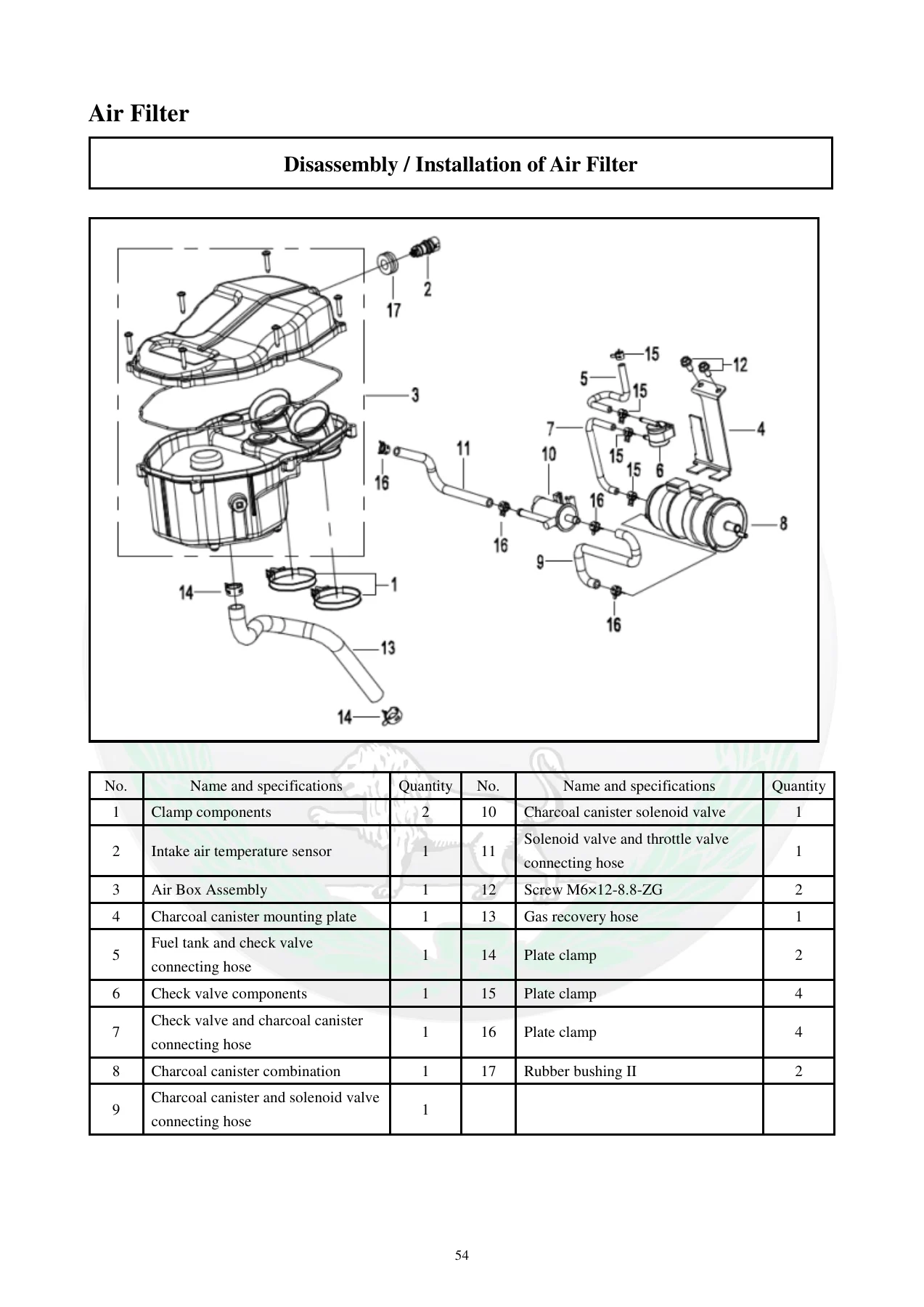
The chassis portion of the Benelli TNT300 Service Workshop Repair Manual provides disassembly, inspection and reassembly procedures for major motorcycle components. Exploded views identify individual parts and fasteners, while the accompanying instructions provide installation sequence and tightening information.
Front and rear wheel sections cover wheel removal, brake rotor removal and installation, bearing replacement, axle inspection, wheel run-out checks, static balancing and reassembly. The brake chapters cover front and rear brake pads, master cylinders, calipers, hoses and brake-fluid procedures. Suspension coverage includes front-fork removal, internal fork disassembly, seal and bushing service, spring inspection, fork-oil filling and reassembly, together with rear shock absorber removal, inspection and installation.
The chassis chapters also address handlebars and controls, steering-head components, swing arm, drive chain, frame and engine mounting, side stand, foot controls, exhaust system, body panels, fuel-tank cowling, lower fairing, tail section, headlight cowling and lighting assemblies. This makes the manual useful for repairs that require access beyond normal maintenance items.
Engine Repair Coverage
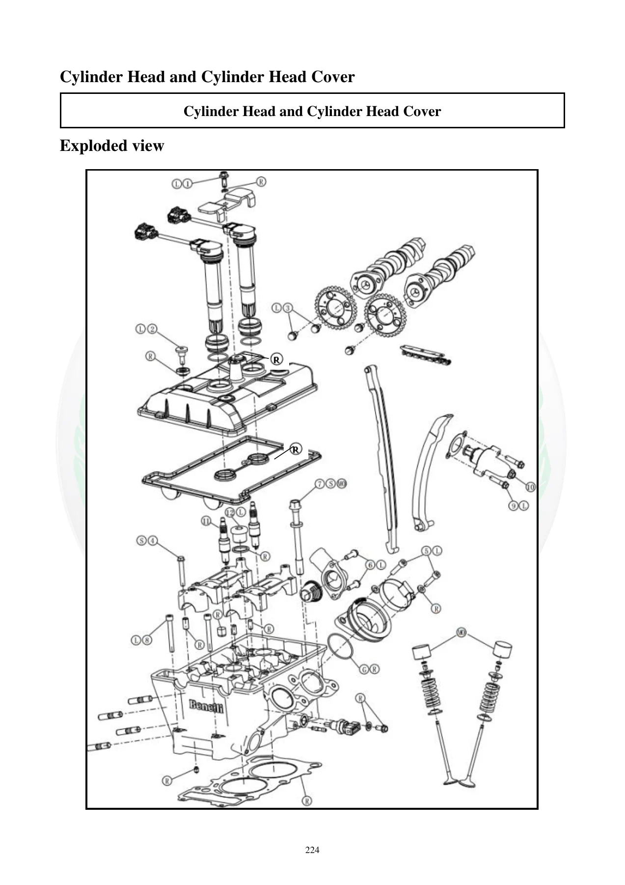
Engine work occupies a major portion of this 488-page TNT300 repair manual. The cylinder-head section includes exploded views, tightening data, technical parameters, special tools and sealants before moving into the cylinder-head cover, camshaft timing-chain tensioner, camshafts, timing chain, cylinder head, valves and intake manifolds.
Detailed technical parameters include camshaft measurements, cylinder compression data, valve clearances, valve dimensions, valve-guide data, valve-seat dimensions and valve-spring limits. Procedures identify where new gaskets, seals and locking agents are required and provide tightening sequences and torque values for critical fasteners.
The clutch chapter covers the right engine cover and clutch assembly. The lubrication chapter includes an engine-oil flow diagram, oil and filter service, oil pan, oil pump, pressure-relief valve, oil-pressure measurement and pressure switch. Crankshaft and transmission coverage extends to crankcase disassembly, crankshaft and connecting rods, pistons, electric starter and gear-change mechanism. Measurement points, wear limits and assembly precautions are included throughout these sections.
Cooling, Fuel Injection and Electrical Systems
The cooling-system chapter covers the water pump, thermostat, coolant-hose connections, radiator disassembly and inspection, cooling fan, radiator cap, water-temperature sensor, radiator assembly and coolant filling. This provides the information required to trace leaks, inspect cooling components and correctly refill the system after service.
Fuel-system coverage includes the fuel tank, fuel pump, throttle body and fuel injectors. The fuel-pump section explains operating principles, component identification, working environment, maintenance and precautions. Throttle-body information covers operation, technical parameters, disassembly, negative-pressure balancing, cleaning, assembly and installation cautions. Fuel-injector material includes operating principles, sealing O-rings, wiring layout, installation requirements, replacement and blockage-related information.
The electrical chapter covers the charging system, battery, stator/generator, regulator/rectifier, ignition system, ignition coil, crankshaft-position sensor, ECU, spark plugs, starting system, starter motor and relay, gauge cluster, ignition switch, horn, handlebar switches, speedometer sensor, relays and fuse block. The fuel-injection electrical section continues with ECU-related checks and individual sensors including water-temperature, intake-air-temperature, intake-manifold-pressure and oxygen sensors, together with the idle-speed stepper motor.
Fault Diagnosis and Circuit Diagrams
A dedicated faults and troubleshooting chapter helps connect symptoms with checks rather than limiting the manual to component replacement. It covers difficulty starting or starting failure, poor running at low speed, poor running at high speed, charging defects, no-spark diagnosis and fuel-injection-system fault diagnosis.
The fuel-injection troubleshooting material includes diagnosis using the FI fault-indicator light, diagnostic apparatus, diagnostic software, common troubleshooting methods and engine working data. The appendices then provide cable, wire and hose wrapping/routing information and TNT300 circuit diagrams for different market configurations.
Chapters Covered
- Chapter I – General Information
- General safety and motorcycle identification
- Features, instruments and lights
- Preparation for disassembly and important assembly information
- Gaskets, O-rings, seals, bearings and connectors
- Special tools
- Chapter II – Specification
- Basic motorcycle specifications
- Engine technical data and detailed engine specifications
- Motorcycle chassis specifications
- Electrical data
- Nut, bolt and screw tightening torques
- Chapter III – Check and Regular Adjustment
- Maintenance and lubrication schedules
- Air filter, fuel hoses, throttle and clutch controls
- Engine oil, oil filter and coolant
- Spark plugs and valve-clearance adjustment
- Brake, drive-chain, steering and suspension checks
- Tires, battery, fuses and lighting
- Section IV – Motorcycle / Chassis
- Front and rear wheels and brake rotors
- Front and rear brake systems
- Front suspension and fork overhaul
- Controls and handlebars
- Rear shock absorber
- Drive chain and rear swing arm
- Frame and engine mounting
- Side stand and foot controls
- Muffler and exhaust system
- Fairings, fenders, tail section and lights
- Chapter V – Engine
- Cylinder head, camshafts, timing chain and valves
- Intake manifolds
- Clutch
- Engine lubrication system and oil-pressure checks
- Crankcase, crankshaft and connecting rods
- Pistons
- Electric starter
- Gear-change mechanism and transmission
- Chapter VI – Cooling System
- Water pump and thermostat
- Coolant hoses, radiator and fan
- Radiator cap and water-temperature sensor
- Cooling-liquid filling
- Chapter VII – Fuel System
- Fuel tank and fuel pump
- Throttle body service and balancing
- Fuel injectors
- Chapter VIII – Electrical System
- Charging and ignition systems
- Battery, stator/generator and regulator/rectifier
- Starter system
- Gauge cluster, switches, horn and sensors
- Relays and fuse block
- Fuel-injection electrical components and ECU
- Chapter IX – Faults and Troubleshooting
- Starting and running faults
- Charging and no-spark diagnosis
- Fuel-injection fault diagnosis
- FI indicator and diagnostic-apparatus procedures
- Diagnostic software and common troubleshooting methods
- Chapter X – Appendices
- Cable, wire and hose routing/wrapping information
- TNT300 circuit diagrams
Taken as a whole, the manual gives a technician a connected reference from routine servicing through major mechanical disassembly and electronic fault diagnosis. Instead of relying only on generic repair practices, the user can work with TNT300-specific clearances, capacities, inspection limits, fastening torques, component layouts, adjustment procedures and diagnostic information.
Service, Repair and Diagnose Your TNT300 with the Correct Reference
The Benelli TNT300 Service Workshop Repair Manual – 488 Page PDF supports maintenance, adjustment, chassis repair, engine overhaul, cooling-system work, fuel-system servicing, electrical testing and fault diagnosis using the procedures and specifications provided for the TNT300. Having the correct service data matters when setting valve clearances, tightening critical fasteners, measuring wear, assembling engine components, servicing brakes and suspension, or tracing fuel-injection and electrical faults.
IMAGES PREVIEW
After purchase, the manual is supplied as an instant PDF download with no physical book and no shipping delay. Save the file to your computer, tablet or phone for workshop reference, and print the pages you need for individual service or repair jobs.


Reviews
There are no reviews yet.