
Biocode Hycel Diana 5 Evolution Xenia Technical Manual 576CA70E April 2006
Original price was: $34.95.$19.95Current price is: $19.95.
Technical manual for the Biocode Hycel Diana 5 Evolution and Xenia hematology analyzers covering installation, counting fluidics, five-part WBC differentiation, cytometer service, troubleshooting, and board wiring. Document reference 576CA70E, modified 19 April 2006.
Description
Biocode Hycel Diana 5 Evolution Xenia Technical Manual 576CA70E April 2006
This Biocode Hycel Diana 5 Evolution Xenia Technical Manual 576CA70E April 2006 is written for service engineers and laboratory technicians who install, calibrate, and keep the Diana Évo / Xénia hematology analyzer running. The instrument measures CBC parameters and a five-part leukocyte differential by combining impedance counting with hydrodynamic focusing and wide-angle light scatter in a dedicated cytometer. The text follows the real work sequence: site preparation and reagent hookup, compiled software sequences, every fluidic counting cycle, quality-control logic, scattergram interpretation, maintenance-program tests, cytometer disassembly, alarm-by-alarm troubleshooting, scheduled part exchanges, and printed wiring diagrams for the mother, sampling, sequence, power, counting, and hemoglobin boards.
File Details
- Manual type: Technical manual
- Brand / models: Biocode Hycel Diana 5 Evolution (Diana Évo) and Xénia
- Language: English (installer screens and some labels also appear in French)
- Page count: 414
- File format: PDF
- Document reference: 576CA70E
- Revision note: Technical manual modified 19/4/06 (cover dated April 2006)
Instrument, Reagents, and Site Requirements
The analyzer plus compressor is specified for 115 V ± 10 % (105–125 V) or 230 V ± 10 % (205–245 V) at a maximum of 1000 VA. Ground quality is treated as mandatory: the ground line must not be interrupted between mains and the instrument plug, and voltage between neutral and ground must stay within 0.5 V. The optional autosampler is listed separately at 115/230 V and 150 VA. Ambient limits are 18 to 30 °C (64 to 86 °F) without condensation. Planned bench space is 1.50 m wide by 0.80 m deep, with a rear opening for fluidic and electrical lines. Published dimensions and weights are 54 × 56 × 56 cm and 40 kg for the analytical module and 42 × 17 × 60 cm and 18 kg for the compressor.
Reagent installation is color-coded. Detergent HEMACORE uses the blue Ellitec sampling assembly and level detector. Diluent HEMATON-5 uses the white connectors (three white fittings plus level detector). Lysing agent HEMALYSE-5 is a small tube with a green Luer fitting into a pierced flask cork. Yellow check valves on the analytical module and compressor both route to the waste container. Waste uses the orange Ellitec fittings and a cap with level detection. Rigid blue pipes carry vacuum and pressure between compressor and module; the black sleeve marks the pressure line (black to black-background fitting). Two electrical cables handle compressor power and command signals.
Host-computer guidance in this Biocode Hycel Diana 5 Evolution Xenia Technical Manual 576CA70E April 2006 lists a minimum Pentium II 200 MHz PC with two serial ports, 4 GB disk, 256 MB RAM, 800 × 600 display, diskette and CD-ROM drives, Windows 2000 or Windows XP Pro, and Internet Explorer 5. Recommended hardware is a 350 MHz Pentium II, 512 MB RAM, and a 17-inch 1024 × 768 display. The installer can choose unit systems (US, SI, SI2, Int’l 1, Int’l 2) that change how WBC, RBC, platelets, Hb, Hct, MCH, and MCHC are printed. A Compile utility turns .zzz sources plus the instrument diskette file param-seq.h60 into working sequence files for one analyzer. Software habilitation is split into operator, supervisor, and service accounts defined at first startup.
How a Count Cycle Is Built
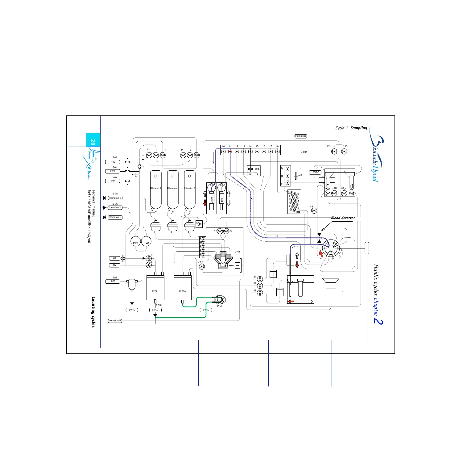
Chapter 2 treats the analyzer as a multitasking fluidic machine. After cap piercing, blood is drawn in two segments separated by a bubble. The first segment rinses needle and tubing; the second fills a factory-calibrated shear-valve loop of 25 ± 2 µl. Sampling stops when blood reaches the optical detector (threshold about 2 M RBC). Whole-blood volume taken is roughly 150 µl. With the sampler, a second 25 ± 2 µl loop is used. First-dilution diluent is 1800 µl, so the nominal diluent-to-sample ratio is 1800 / 25 = 72 (range about 66.67 to 78.26 depending on actual loop volume stored in machine parameters).
Later cycles insert an isolating bubble, push the 25 µl loop with 1.775 ml of diluent into the WBC preparation chamber (1/72), homogenize that dilution while the 2.5 ml syringe aspirates HEMALYSE into the preheater, then transfer 490 µl of the first dilution into the lower 25 µl dilution loop. Concurrently the three reservoirs (sheath 1, sheath 2, diluent) are topped to their detection electrodes and the vacuum trash is drained. A second bubble sampled through valve 38 frames the RBC dilution on both sides of the valve. The dilution loop is then pushed with about 2000 µl of diluent into the RBC chamber under agitation while the WBC chamber is flushed to vacuum trash. Every later cycle in the chapter continues this style of annotated schematic: active valves darkened, fluid paths bolded, arrows for direction, so a technician can watch a live sequence and name the failing element.
Measurement Science, Artefacts, and Scattergrams
The technical-discussion chapter explains why hydrodynamic focusing is used instead of a traditional aperture-only hematology path, then walks through internal quality control, moving averages, calibration and cleaning, and reference-value handling. System-error notes cover missed blood detection, pressure faults, and RBC/WBC counting kinetics. Biological-artefact pages list the usual high/low traps for each reported parameter: cryoglobulin and giant platelets inflating RBC; cold agglutinins and in-vitro hemolysis dropping RBC or Hb; carboxyhemoglobin above 10 %, lipemia, hyperbilirubinemia, and WBC above 30 giga/L raising Hb; hyponatremia raising Hct; hyperglycemia and reduced RBC deformability raising MCV; MCH near the ISLH figure of 30.5 pg; MCHC near 33–34 % with values above 36 % treated as artefact or MCV bias (saturation given as 37 %). Software version V5.1 flags Hb, MCH, and MCHC as suspect when WBC exceeds 50 giga/L.
WBC work covers physical measures, chemical preparation, cells counted, and the differentiation algorithm (eosinophils, abnormal scattergrams, NRBC/platelet aggregates, debris, immature cells, density scattergram, basophils, resistant RBC). Limits of differentiation produce NIL (Non Identified Leucocytes) when basophils or monocytes cannot be estimated; mono- and bidirectional host transfer rules for NIL are spelled out, including Hemacell Plus compatible mode. Morphological alarms raise a microscope icon and mark the differential Positive: debris, Plasmodium, NRBC, resistant RBC/erythroblasts, and related flags. Quantitative alarms, default versus positive validation, and result transmission close the chapter. A long atlas then shows five-part differential scattergrams, suspicious alerts, LMN histograms, calibrator and control plots, RBC, artefact, platelet, WBC, and eosinophil pictures, plus handling-error and abnormal-differentiation examples a bench tech can match to printed reports.
Fluidic Hardware and Maintenance Software
The fluidics volume is an illustrated parts map rather than a narrative. Analyzer fluidics include high pressure and high vacuum, decanter cleaning, internal and external sheath regulators, stand-by versus in-cycle pressure and vacuum, sheath pressures, the SERCOM pump and atmospheric trash, internal and external sheath reservoirs with a written sheath-reservoir cleaning procedure, the diluent reservoir, and the sheath-1, external-sheath, and diluent filters. Compressor-housing fluidics, new-compressor connections, and rear-panel external connections follow. Name-sorted and reference-sorted indexes plus a complete fluidic diagram let a tech find a Lee valve, Cavro three-way, minisol, or filter by either wording or Li number.
Maintenance software is organized by module. After log-in, the fluidic module offers Tests, Embase, Prime/Drain, Research of contaminations, and a Miscellaneous window. The power module exposes counting status, ADC/DAC, TTL I/O, stirring motors, and detectors. Software adjustments edit the parameters file, gains, and thresholds. Sampling and sampler pages drive motors and detectors. Acquisition-module pages teach histogram and scatter setup, then how to read kinetic tables, volume histograms, and color scattergrams inside the service program. Cytometer work is a full mechanical procedure: cover and injector removal, injector and ruby-holder cleaning, reinstallation, and complete cytometer exchange. After exchange, 5 µm latex particles pre-align DC and laser channels; final WALS (wide-angle light scatter) alignment uses control blood so the neutrophil cluster Y coordinate matches the control sheet (typical WALS 30 to 32). Preamplifier pots P1 (DC) and P2 (laser) are adjusted so the scatter spot sits at Y = 115 ± 1. Matching-cell percentage must exceed 75 % of the DC count and Y standard deviation should be 10 ± 3; out-of-range figures point to sheath-pressure error, dirty aperture, or a cytometer that must be swapped.
Alarms, Scheduled Service, and Electronics
Troubleshooting is grouped the way the instrument reports trouble: reagent alarms (Hematon 5, Hemacore, Hemalyse, trash), fluidic alarms (pressure, vacuum), measure alarms (WBC, Hb, abnormal gain on RBC/WBC/Plt, temperatures, blood detectors), mechanical alarms (BSV, turret, piercing needle, sampling needle, dilutors), and communication/LIS alarms. Practical checks include backup-battery voltage above 3 V (3.6 V listed), +5 V / ±15 V rails with +5 V raised to 5.2 V if needed, RAM-clear by unseating boards, and setting the serial protocol to NONE when no LIS is attached so false COM-2 alarms stop.
Three printed schedules—semi-annual, yearly, and biennial—are built around bleach cleaning of the shear valve and loops, cytometer, needles, rinsing well, decanters, vacuum trash, valves S6/S25/S26/S29/S21/S22, valve sub-bases, and WBC/RBC transfer paths, plus pressure/vacuum verification, platelet background, impedance gain on 5 µm latex, laser WALS printouts, and a seven-replicate precision run on fresh normal blood. Biennial extra work replaces pressure/vacuum filters, dirty injection tubes, waste check valves, syringe tips, selected minisol and microsol valves, HEMATON and HEMACORE check valves, piercing and sampling needles, pressure regulators, Lee valves S40 and S41 on the WBC line, Cavro three-way valves, and the 1 ml and 2.5 ml dilutor syringes. Power-supply targets listed on that schedule are +5.2 V, ±15 V, +28 V, and +24 V. A two-year parts table gives Li references for silencers, check valves, filters, needles, regulators, FAS seals, and related hardware.
Closing chapters print wiring between sheath, sampling, reset, cuves, and cytometer boards and the mother board, then full schematics for the mother board, sampling board, Power P1 logic, sequence board, Power P2 analog, counting board, preamplifier, and hemoglobin preamplifier (zero and automatic gain procedures). A power-supply diagram and implantation drawing finish the book.
Chapters Covered
- Installation — Environment (power supply, temperature and humidity, dimensions and weight); Physical installation (unpacking, reagents, compressor); Required PC configuration; Installation procedure and Compile program; First startup and program preferences
- Fluidic cycles — Counting cycles from sampling through dilution, bubble isolation, RBC/WBC chamber work, transfer to the cytometer, and cleaning
- Diana Évo / Xénia technical discussion — Flow cytometry and hydrodynamic focusing; Internal quality control, moving average, calibration and cleaning; System errors; Biological artefacts on WBC, RBC, Hb, Hct, MCV, MCH, MCHC, platelets; WBC differentiation algorithm, NIL limits, morphological and quantitative alarms; Validation and result transmission; Scattergram atlas (five-part differential, alerts, calibrators, controls, artefacts, handling errors)
- Fluidics — Components; Analyzer fluidics (high pressure/vacuum, sheath regulators, stand-by and cycle pressures, reservoirs, filters); Compressor housing; External connections; Name and reference indexes; Fluidic diagram
- Maintenance software — Access; Fluidic, power, sampling, and sampler modules; Software and acquisition-module adjustments; Interpretation of maintenance data
- Cytometer — Routine cleaning; Dismounting injector and ruby holder; Replacement and cytometer exchange; Acquisition adjustments after exchange
- Troubleshooting on Diana Évo / Xénia — Reagent, fluidic, measure, mechanical, and communication alarms
- Maintenance schedules — Necessary parts; Semi-annual, yearly, and biennial checklists
- Wiring and board schematics — Sheath, sampling, reset, cuves, and cytometer connections; Mother, sampling, Power P1, sequence, Power P2, counting, and preamplifier drawings
- Hemoglobin preamplifier — Exchange, zero and automatic gain, schematics
- Power supply — Diagram and implantation
Taken together, the Biocode Hycel Diana 5 Evolution Xenia Technical Manual 576CA70E April 2006 gives a field engineer the sequence files, fluid maps, optical alignment numbers, alarm trees, and board drawings needed to put the analyzer on the bench and keep counts and differentials inside specification.
Use This Manual on the Bench
With this file a technician can site the analyzer and compressor, plumb HEMATON-5, HEMACORE, HEMALYSE-5 and waste, compile instrument sequences, watch each counting cycle against the printed fluid diagrams, interpret five-part scattergrams and NIL/morphology flags, clean or exchange the cytometer and shear-valve loops, set DC and laser gains against latex and control blood, work reagent and pressure alarms in the order the software raises them, and run the semi-annual through biennial part list. Following the printed volumes, ratios, WALS targets, and rail voltages matters because a dirty sheath regulator, a mistimed bubble, or a drifted P2 pot changes kinetics and can shift MCV, platelet background, or the neutrophil cluster before any numeric flag appears.
Delivery is an instant PDF download after payment. There is no shipped binder. Open the file on a workshop PC or tablet and print the cycle drawings, maintenance checklists, or board schematics you need for the job.
Reviews
There are no reviews yet.