Bobcat 335 Compact Excavator Service Manual 6986949 (5-10) – PDF DOWNLOAD
$35.95
Bobcat 335 Compact Excavator Service Manual 6986949 (5-10) – PDF DOWNLOAD
S/N AAD111001 & Above
S/N A9KA11001 & Above
Description
Bobcat 335 Compact Excavator Service Manual 6986949 (5-10) – PDF DOWNLOAD
FILE DETAILS:
Bobcat 335 Compact Excavator Service Manual 6986949 (5-10) – PDF DOWNLOAD
Language : English
Pages : 952
Downloadable : Yes
File Type : PDF
Size:26.9 MB
DESCRIPTION:
Bobcat 335 Compact Excavator Service Manual 6986949 (5-10) – PDF DOWNLOAD
S/N AAD111001 & Above
S/N A9KA11001 & Above
FOREWORD
This manual is for the Bobcat excavator mechanic. It provides necessary servicing and adjustment procedures for the Bobcat excavator and its component parts and systems. Refer to the Operation & Maintenance Manual for operating instructions, starting procedure, daily checks, etc.
SAFETY INSTRUCTIONS
Instructions are necessary before operating or servicing machine. Read and understand the Operation & Maintenance Manual, Operator’s Handbook and signs (decals) on machine. Follow warnings and instructions in the manuals when making repairs, adjustments or servicing. Check for correct function after adjustments, repairs or service. Untrained operators and failure to follow instructions can cause injury or death.
The following publications provide information on the safe use and maintenance of the Bobcat machine and attachments
TABLE OF CONTENTS:
Bobcat 335 Compact Excavator Service Manual 6986949 (5-10) – PDF DOWNLOAD
ALPHABETICAL INDEX 5
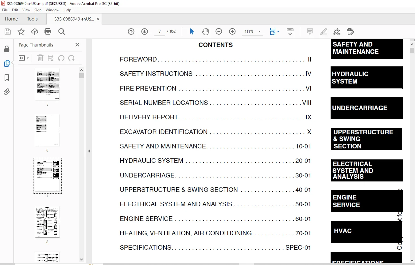
CONTENTS 7
FOREWORD 8
SAFETY INSTRUCTIONS 10
FIRE PREVENTION 12
Maintenance 12
Operation 12
Electrical 12
Hydraulic System 12
Fueling 12
Starting 12
Spark Arrestor Exhaust System 12
Welding And Grinding 13
Fire Extinguishers 13
SERIAL NUMBER LOCATIONS 14
Excavator Serial Number 14
Engine Serial Number 14
DELIVERY REPORT 15
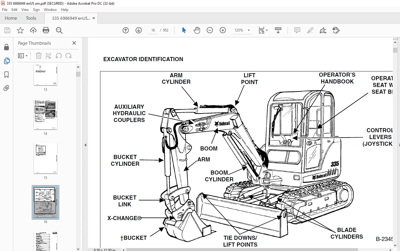
EXCAVATOR IDENTIFICATION 16
SAFETY AND MAINTENANCE 17
LIFTING AND BLOCKING THE EXCAVATOR 21
Procedure 21
UPPERSTRUCTURE SLEW LOCK 23
Operation 23
LIFTING THE EXCAVATOR 25
Procedure 25
OPERATOR CAB (ROPS / TOPS) 27
Description 27
Cab Door 27
Front Window 28
Front Wiper 30
Window Washer Reservoir 30
Right Side Window 30
Heating, Ventilation And Air Conditioning Duct 31
Heating, Ventilation And Air Conditioning Duct (Cont’d) 32
TRANSPORTING THE EXCAVATOR ON A TRAILER 33
Loading And Unloading 33
Fastening 33
TAILGATE 35
Opening And Closing 35
Adjusting The Bumper 35
Adjusting The Latch 35
RIGHT SIDE COVER 37
Opening And Closing 37
Adjusting The Bumper 37
Adjusting The Latch 37
SERVICE SCHEDULE 39
Chart 39
AIR CLEANER SERVICE 41
Daily Check 41
Replacing Filter Elements 41
HEATER AIR FILTER (WITH CAB OPTION ONLY) 43
Removal And Installation 43
ENGINE COOLING SYSTEM 45
Cleaning 45
Checking Level 45
Removing And Replacing Coolant 46
FUEL SYSTEM 49
Fuel Specifications 49
Biodiesel Blend Fuel 49
Fuel Filter 51
Draining The Fuel Tank 51
Removing Air From The Fuel System 52
ENGINE LUBRICATION SYSTEM 53
Checking And Adding Engine Oil 53
Engine Oil Chart 53
Removing And Replacing Oil And Filter 54
HYDRAULIC SYSTEM 55
Checking And Adding Fluid 55
Removing And Replacing Hydraulic Filter 56
Removing And Replacing Hydraulic Case Drain Filter 56
Removing And Replacing Hydraulic Fluid 57
LUBRICATING THE EXCAVATOR 59
Lubrication Locations 59
TRAVEL MOTOR 63
Checking And Adding Oil 63
Removing And Replacing Oil 63
SPARK ARRESTOR MUFFLER 65
Cleaning Procedure 65
ACCESSORY DRIVE BELT 67
Belt Adjustment 67
Belt Replacement 67
SEAT BELT 69
Inspection And Maintenance 69
PIVOT PINS 71
Inspection And Maintenance 71
EXCAVATOR STORAGE AND RETURN TO SERVICE 73
Storage 73
Return To Service 73
STOPPING THE ENGINE AND LEAVING THE EXCAVATOR 75
Procedure 75
Emergency Exits 76
MOTION ALARM SYSTEM (IF EQUIPPED) 77
Description 77
Inspecting 77
Adjusting Switch Position 77
HYDRAULIC SYSTEM 79
HYDRAULIC / HYDROSTATIC SCHEMATICS 85
HYDRAULIC SYSTEM INFORMATION 89
Glossary Of Hydraulic/Hydrostatic Symbols For Excavators 89
Troubleshooting The Hydraulic Circuit 93
Troubleshooting The Cylinder Circuit 94
Troubleshooting The Swing (Upperstructure Slew) Circuit 95
Troubleshooting The Travel Circuit 96
BOOM CYLINDER 97
Testing 97
Removal And Installation 99
Parts Identification 102
Disassembly 103
Assembly 106
ARM CYLINDER 109
Testing 109
Removal And Installation 111
Parts Identification 113
Disassembly 114
Assembly 117
BOOM SWING CYLINDER 121
Testing 121
Removal And Installation 123
Parts Identification 125
Disassembly 126
Assembly 128
BUCKET CYLINDER 131
Testing 131
Removal And Installation 133
Parts Identification 135
Disassembly 136
Assembly 138
BLADE CYLINDER 141
Testing 141
Removal And Installation 142
Parts Identification 143
Disassembly 144
Assembly 146
CLAMP CYLINDER 149
Testing 149
Removal And Installation 150
Parts Identification 151
Disassembly 152
Assembly 155
ANGLE BLADE CYLINDER 161
Testing 161
Removal And Installation 162
Parts Identification 164
Disassembly 165
Assembly 167
MAIN RELIEF VALVE 171
Testing And Adjusting The Main Relief Valve 171
PORT RELIEF VALVES 175
Testing And Adjusting The Port Relief Valve Pressure 175
CROSSPORT RELIEF VALVES 177
Testing And Adjusting The Crossport Relief Valve 177
PRESSURE REDUCING VALVE 181
Testing And Adjusting The Pressure Reducing Valve 181
HYDRAULIC CONTROL VALVE 183
Description 183
Removal And Installation 183
Identification Chart 186
Disassembly 187
Right Travel Valve Section Disassembly And Assembly 189
Left Travel Valve Section Disassembly And Assembly 192
Slew Valve Section Disassembly And Assembly 195
Blade Valve Section Disassembly And Assembly 201
Bucket Valve Section Disassembly And Assembly 212
Arm Valve Section Disassembly And Assembly 218
Boom Valve Section Disassembly And Assembly 224
Boom Swing Valve Section Disassembly And Assembly 230
Auxiliary Valve Section Disassembly And Assembly 236
Inlet Section Disassembly And Assembly 244
Assembly 249
HYDRAULIC PUMP 255
Piston Pump Work Sheet 255
Description 258
Testing The Piston Pump 258
Test Fitting Installation 258
Torque Limiter Adjustment 265
Testing Auxiliary Hydraulic Flow 268
Removal And Installation 270
Coupler Removal And Installation 271
Hydraulic Pump Start Up 272
Parts Identification (Torque Limiter Valve) 273
Torque Limiter Valve Removal 274
Torque Limiter Valve Disassembly 275
Torque Limiter Valve Assembly 279
Initial Torque Limiter Valve Setting 282
Torque Limiter Valve Installation 284
Parts Identification (Pump Control) 285
Pump Control Removal And Installation 286
Pump Control Disassembly And Assembly 286
Parts Identification (Piston Pump) 292
Piston Pump Disassembly 293
Piston Pump Assembly 302
MANIFOLD ASSEMBLY/ ACCUMULATOR 313
Description 313
Removal And Installation 313
Parts Identification 316
Disassembly And Assembly 317
TRAVEL MOTOR 327
Description 327
Removal And Installation 327
Parts Identification 328
Disassembly 329
Assembly 339
SWIVEL JOINT 351
Description 351
Removal And Installation 351
Parts Identification 353
Disassembly 354
Assembly 355
SWING MOTOR 359
Description 359
Removal And Installation 359
Parts Identification 361
Disassembly 362
Assembly 367
SWING MOTOR DRIVE CARRIER 373
Description 373
Removal And Installation 373
Parts Identification 374
Disassembly 375
Assembly 377
CONTROL PATTERN SELECTOR VALVE 381
Description 381
Removal And Installation 381
Parts Identification 382
Disassembly 383
Assembly 384
RIGHT CONTROL LEVER (JOYSTICK) 385
Description 385
Testing 385
Handle Removal And Installation 386
Removal And Installation 390
Parts Identification 393
Disassembly 394
Assembly 399
LEFT CONTROL LEVER (JOYSTICK) 405
Description 405
Testing 405
Handle Removal And Installation 406
Removal And Installation 409
Parts Identification 412
Disassembly 413
Assembly 418
HYDRAULIC FILTER 423
Description 423
Housing Removal And Installation 423
CASE DRAIN FILTER 425
Description 425
Housing Removal And Installation 425
HYDRAULIC RESERVOIR 427
Description 427
Removal And Installation 427
OIL COOLER 429
Description 429
Removal And Installation 429
DIRECT TO TANK VALVE 431
Description 431
Removal And Installation 431
Parts Identification 432
Disassembly And Assembly 433
HYDRAULIC X-CHANGE VALVE 435
Removal And Installation 435
Parts Identification 439
Disassembly 440
Assembly 447
BOOM SWING LOCK VALVE 455
Removal And Installation 455
Parts Identification 456
Disassembly 457
Assembly 460
TRAVEL CONTROL VALVE 465
Removal and Installation 465
Parts Identification 466
Disassembly And Assembly 467
ANGLE BLADE VALVE 471
Description 471
Testing And Adjusting Port Relief Valves 471
Testing And Adjusting Sequence Valve 473
Removal And Installation 475
Parts Identification 478
Disassembly 479
Assembly 492
SLEW LOCK VALVE 505
Description 505
Removal And Installation 505
Parts Identification 506
Disassembly And Assembly 507
UNDERCARRIAGE 511
BLADE 513
Description 513
Blade Removal And Installation 513
ANGLE BLADE ASSEMBLY 515
Removal And Installation 515
ANGLE BLADE 517
Removal And Installation 517
ANGLE BLADE CUTTING EDGE 519
Removal And Installation 519
TRACK FRAME COMPONENTS 521
Description 521
Track Lug Height 521
Checking Tension 522
Adjusting Tension 524
Rubber Track Removal And Installation 525
Steel Track Removal And Installation 528
Idler (Front) Removal And Installation 532
Idler (Front) Parts Identification 533
Idler (Front) Disassembly 534
Idler (Front) Assembly 536
Recoil Spring Assembly And Cylinder Removal And Installation 539
Recoil Spring Assembly And Cylinder Disassembly And Assembly (S/N A9KA11100 & Below And AAD114409 & Below) 540
Recoil Spring Cylinder Parts Identification (S/N A9KA11101 & Above And AAD114410 & Above) 541
Recoil Spring Assembly And Cylinder Disassembly And Assembly (S/N A9KA11101 & Above And AAD114410 & Above) 542
Roller Removal And Installation 544
Upper Roller Parts Identification 545
Upper Roller Disassembly 546
Upper Roller Assembly 547
Lower Roller Parts Identification 550
Lower Roller Disassembly 551
Lower Roller Assembly 553
Track Guide Removal And Installation 555
Sprocket Removal And Installation 555
Track Damage Identification 556
SWING CIRCLE GEAR 567
Removal 567
Installation 568
UPPERSTRUCTURE & SWING SECTION 569
UPPERSTRUCTURE 573
Description 573
Removal 573
Installation 576
CANOPY 579
Removal And Installation 579
CAB 583
Removal And Installation 583
Door Removal And Installation 588
Front Window Removal And Installation 589
Right Side Rear Sliding Window Removal And Installation 592
Right Side Front Sliding Window Removal And Installation 592
Glass Removal 593
Right Side Front And Rear Sliding Window Weather Strip Removal And Installation 594
Right Side Front And Rear Sliding Window Wiper Strip Removal And Installation 594
Glass Installation 595
SEAT AND SEAT MOUNT 601
Seat Mount Removal And Installation 601
Seat Removal And Installation 601
RIGHT CONSOLE 603
Description 603
Console Cover Removal And Installation 603
Console Frame Removal And Installation 604
Console Frame Disassembly And Assembly 606
LEFT CONSOLE 607
Description 607
Joystick Console Cover (Bottom) Removal And Installation 607
Joystick Console Cover (Top) Removal And Installation 607
Left Rear Console Cover Removal And Installation 609
Compression Spring Removal And Installation 610
Compression Spring Disassembly And Assembly 611
Lever Removal And Installation 613
Joystick Console Frame Removal And Installation 615
Joystick Console Frame Disassembly And Assembly 619
Left Console Frame Removal And Installation 622
BLADE CONTROL 623
Removal And Installation 623
Linkage Removal And Installation 624
Linkage Disassembly And Assembly 625
UPPERSTRUCTURE SLEW LOCK 627
Removal And Installation 627
Disassembly And Assembly 627
FLOOR MAT & FLOOR PANEL 629
Description 629
Removal And Installation (Canopy Equipped) 629
Removal And Installation (Cab Equipped) 631
BOOM SWING PEDAL 635
Description 635
Removal And Installation 635
Disassembly And Assembly 635
Linkage Removal And Installation 637
TRAVEL LEVER/PEDALS 639
Description 639
Removal And Installation 639
Disassembly And Assembly 640
Adjustment 642
Linkage Removal And Installation 644
FUEL TANK 645
Removal And Installation 645
HORN 649
Removal And Installation 649
SWING FRAME 651
Description 651
Removal And Installation 651
Hose Routing 655
Bushing Removal And Installation 656
Swing Frame Bushing Removal And Installation 656
BOOM 659
Description 659
Removal And Installation 659
Boom Bushing Removal And Installation 660
ARM 661
Description 661
Removal And Installation 661
Arm To Boom Bushing Removal And Installation 662
Arm To Bucket & Bucket Link Bushing Removal And Installation 663
BUCKET 665
Removal And Installation (Pin-On X-Change) 665
Removal And Installation (Bolt-On X-Change) 671
Removal And Installation (Hydraulic X-Change) 678
Bucket Teeth Removal And Installation 683
Bucket Side Cutting Edge Removal And Installation 684
TAILGATE 685
Removal And Installation 685
Latch Removal And Installation 686
X-CHANGE 687
Pin-On Removal And Installation 687
Pin-On Disassembly And Assembly 688
X-CHANGE (HYDRAULIC) 689
Removal And Installation 689
Parts Identification 692
Disassembly 693
Assembly 698
RIGHT SIDE COVER 707
Removal And Installation 707
Latch Removal And Installation 708
ELECTRICAL SYSTEM AND ANALYSIS 709
ELECTRICAL SCHEMATICS 711
ELECTRICAL SYSTEM INFORMATION 713
Glossary Of Electrical Symbols 713
Harness Connectors 716
Troubleshooting 718
Description 719
Fuse And Relay Locations/Identification 719
BATTERY 721
Removal And Installation 721
Servicing 722
Using A Booster Battery (Jump Starting) 723
ALTERNATOR 727
Belt Adjustment 727
Charging System Inspection 728
Alternator Voltage Testing 729
Low Voltage Testing 729
High Voltage Testing 730
Removal And Installation 731
Parts Identification 733
STARTER 735
Testing 735
Removal And Installation 736
Part Identification 737
LIGHTS 739
Upperstructure Light Removal And Installation 739
Upperstructure Light Disassembly And Assembly 739
Boom Light Removal And Installation 740
Boom Light Bulb Replacement 740
MAGNETIC LOCKOUT SENSOR 741
Testing Left Console Magnetic Lockout Sensor 741
Left Console Magnetic Lockout Sensor Removal And Installation 742
FUEL LEVEL SENDER 745
Removal And Installation 745
Testing 746
DIAGNOSTIC SERVICE CODES 747
Description 747
Service Codes List 748
DELUXE INSTRUMENT PANEL SETUP 749
Passwords 749
Password Entry (For Starting and Operating the Machine) 749
Changing The Owner Or Operator Password 749
Password Lockout Feature 750
Job Clock 750
RPM 750
ENGINE SERVICE 751
ENGINE INFORMATION 753
Description 753
Specifications 754
Fuel Injection Nozzles 754
Fuel Injection Pump 754
Cylinder Head 754
Valves 754
Valve Springs 755
Valve Timing 755
Rocker Arms 755
Camshaft 755
Tappet 755
Cylinders 756
Piston Rings 756
Pistons 756
Connecting Rods 756
Oil Pump 756
Crankshaft 757
Timing Gear 757
Thermostat 757
Engine Bolt Torque 758
Crankshaft Re-Grind Data 759
Torque Values 760
Troubleshooting 760
Engine Removal And Installation 762
Engine Mount Replacement 768
Compression – Checking 771
ENGINE SPEED CONTROL 773
Removal And Installation 773
Adjustment 774
SPARK ARRESTOR MUFFLER 775
Removal And Installation 775
AIR CLEANER 777
Removal And Installation 777
ENGINE COOLING SYSTEM 779
Radiator Removal And Installation 779
Water Pump Removal And Installation 781
Water Pump Disassembly And Assembly 781
Thermostat Housing Removal And Installation 782
Testing The Thermostat 782
LUBRICATION SYSTEM 783
Oil Pan Removal And Installation 783
Oil Pump Removal And Installation 783
Oil Pump Inspection 784
Engine Oil Pressure – Testing 785
FUEL SYSTEM 787
Fuel Camshaft Removal And Installation 787
Fuel Camshaft Governor Disassembly And Assembly 788
Fuel ShutOff Solenoid – Checking 789
Fuel Shutoff Solenoid Removal And Installation 790
Fuel Injection Pump Removal And Installation 791
Injection Pump – Timing 794
Fuel Injector Removal And Installation 796
Fuel Injector Nozzle Pressure – Checking 798
Nozzle Spray Condition 798
Valve Seat Tightness 799
CYLINDER HEAD 801
Glow Plug – Testing 801
Glow Plug Removal And Installation 802
Valve Clearance Adjustment 803
Valve Timing – Checking 804
Cylinder Head Removal And Installation 805
Cylinder Head Disassembly And Assembly 808
Cylinder Head Servicing 808
Cylinder Head Top Clearance 809
Valve Guide – Checking 809
Reconditioning The Valve And Valve Seat 811
Valve Spring 812
Valve Tappets 813
Rocker Arm And Shaft – Checking 813
CRANKSHAFT AND PISTONS 815
Piston And Connecting Rod Removal And Installation 815
Piston And Connecting Rod – Servicing 817
Cylinder Bore – Checking 819
Connecting Rod – Alignment 819
Crankshaft And Bearings Removal And Installation 820
Crankshaft And Bearings – Servicing 822
CAMSHAFT AND TIMING GEARS 827
Timing Gearcase Cover Removal And Installation 827
Timing Gears Backlash – Checking 829
Idler Gear And Shaft Removal And Installation 830
Camshaft – Servicing 832
Idler Gear And Shaft – Servicing 833
FLYWHEEL AND HOUSING 835
Flywheel Housing Removal And Installation 835
Hydraulic Pump Coupler Removal And Installation 836
Flywheel Removal And Installation 837
Flywheel Ring Gear 837
FAN 839
Removal And Installation 839
HEATING, VENTILATION, AIR CONDITIONING 841
HEATER COIL 843
Removal And Installation With A/C 843
Removal And Installation Without A/C 843
BLOWER FAN 845
Removal And Installation 845
Disassembly And Assembly 846
Resistor Removal And Installation 847
HEATER VALVE 849
Removal And Installation 849
AIR CONDITIONING SYSTEM FLOW 852
Principals 852
Chart 853
COMPONENTS 855
Identification 855
SAFETY 859
Safety Equipment 859
REGULAR MAINTENANCE 861
Heater Air Filter 861
Engine Accessory Drive Belt 861
Cleaning The Condenser 861
BASIC TROUBLESHOOTING 863
Poor A/C Performance 863
Cleaning The A/C Evaporator Coil & Heater Coil 864
Engine Accessory Drive Belt 865
Electrical System 866
Engine Coolant By-Passing The Heater Valve 875
Heater Valve Not Opening Or Closing 876
GENERAL AIR CONDITIONING SERVICE GUIDELINES 879
Compressor Oil 879
Compressor Oil Check 880
Component Replacement And Refrigeration Leaks 881
SYSTEM TROUBLESHOOTING CHART 883
Blower Motor Does Not Operate 883
Gauge Pressure Related Troubleshooting 884
TEMPERATURE/PRESSURE 887
Chart 887
AIR CONDITIONING SERVICE 889
Chart 889
SYSTEM CHARGING AND RECLAMATION 891
Reclamation Procedure 891
Charging With A Manifold Gauge Set 894
COMPRESSOR 897
Removal And Installation 897
Clutch Disassembly And Assembly 899
CONDENSER 903
Removal And Installation 903
RECEIVER/DRIER 905
Receiver/Drier Removal And Installation 905
PRESSURE RELIEF VALVE 907
Removal And Installation 907
PRESSURE SWITCH 909
Removal And Installation 909
EVAPORATOR / HEATER UNIT 911
Removal And Installation 911
Disassembly And Assembly 912
THERMOSTAT 913
Removal And Installation 913
EXPANSION VALVE 915
Removal And Installation 915
EVAPORATOR 917
Removal And Installation 917
SPECIFICATIONS 919
335 Excavator SPECIFICATIONS 921
Dimensions 921
Excavator With Optional Angle Blade Dimensions 923
Performance 924
Controls 924
Engine 924
Hydraulic System 925
Hydraulic Cylinders 925
Hydraulic Cycle Times 925
Electrical 926
Drive System 926
Slew System 926
Undercarriage 926
Capacities 926
Tracks 926
Ground Pressure 926
ENGINE SPECIFICATIONS 927
Fuel Injection Nozzles 927
Fuel Injection Pump 927
Cylinder Head 927
Valves 927
Valve Springs 928
Valve Timing 928
Rocker Arms 928
Camshaft 928
Tappet 928
Cylinders 929
Piston Rings 929
Pistons 929
Connecting Rods 929
Oil Pump 929
Crankshaft 930
Timing Gear 931
Thermostat 931
Engine Bolt Torque 932
Crankshaft Re-Grind Data 933
TORQUE SPECIFICATIONS 935
Torque For General SAE Bolts 935
Torque For General Metric Bolts 936
HYDRAULIC CONNECTION SPECIFICATIONS 937
O-Ring Face Seal Connection 937
Straight Thread O-Ring Fitting 938
Tubelines And Hoses 938
Flare Fitting 938
Port Seal Fitting 939
HYDRAULIC FLUID SPECIFICATIONS 941
Specifications 941
FUEL, COOLANT AND LUBRICANTS 943
Chart 943
CONVERSIONS 945
Decimal And Millimeter Equivalents 945
U S To Metric Conversion Chart 945
SERVICE MANUAL REVISION 947
Revision No: 335 – 1 947
Revision No: 335 – 2 949
Revision No: 335 – 3 951
IMAGES PREVIEW OF THE MANUAL:
Need help? Contact: [email protected]
https://vimeo.com/841231846?share=copy
PLEASE NOTE:
- This is the same manual used by the dealers to diagnose and troubleshoot your vehicle
- You will be directed to the download page as soon as the purchase is completed. The whole payment and downloading process will take anywhere between 2-5 minutes
- Need any other service / repair / parts manual, please feel free to contact [email protected] . We still have 50,000 manuals unlisted
s.m