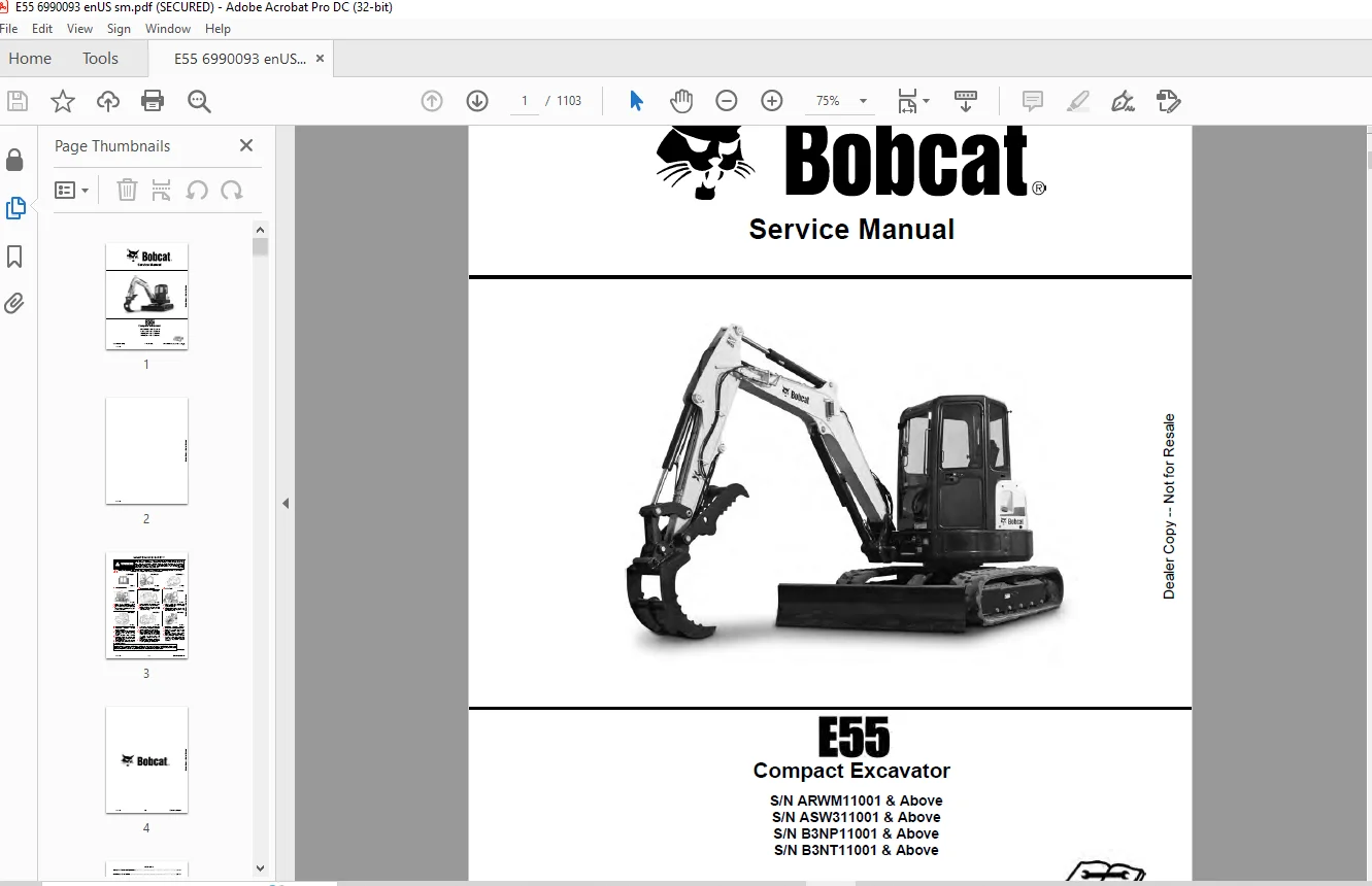
Bobcat E55 Compact Excavator Service Manual 6990093 (01-20) – PDF DOWNLOAD
$35.95
Bobcat E55 Compact Excavator Service Manual 6990093 (01-20) – PDF DOWNLOAD
S/N ARWM11001 & Above
S/N ASW311001 & Above
S/N B3NP11001 & Above
S/N B3NT11001 & Above
Description
Bobcat E55 Compact Excavator Service Manual 6990093 (01-20) – PDF DOWNLOAD
FILE DETAILS:
Bobcat E55 Compact Excavator Service Manual 6990093 (01-20) – PDF DOWNLOAD
Language : English
Pages :1103
Downloadable : Yes
File Type : PDF
DESCRIPTION:
Bobcat E55 Compact Excavator Service Manual 6990093 (01-20) – PDF DOWNLOAD
FOREWORD
This manual is for the Bobcat excavator mechanic. It provides necessary servicing and adjustment procedures for the Bobcat excavator and its component parts and systems. Refer to the Operation & Maintenance Manual for operating instructions, starting procedure, daily checks, etc.
SAFETY INSTRUCTIONS
Instructions are necessary before operating or servicing machine. Read and understand the Operation & Maintenance Manual, Operator’s Handbook and signs (decals) on machine. Follow warnings and instructions in the manuals when making repairs, adjustments or servicing. Check for correct function after adjustments, repairs or service. Untrained operators and failure to follow instructions can cause injury or death.
The following publications provide information on the safe use and maintenance of the Bobcat machine and attachments:
- The Delivery Report is used to assure that complete instructions have been given to the new owner and that the machine is in safe operating condition.
- The Operation & Maintenance Manual delivered with the machine or attachment contains operating information as well as routine maintenance and service procedures. It is a part of the machine and can be stored in a container provided on the machine. Replacement Operation & Maintenance Manuals can be ordered from your Bobcat dealer.
- Machine signs (decals) instruct on the safe operation and care of your Bobcat machine or attachment. The signs and their locations are shown in the Operation & Maintenance Manual. Replacement signs are available from your Bobcat dealer.
- An Operator’s Handbook fastened to the operator cab. It’s brief instructions are convenient to the operator. The handbook is available from your dealer in an English edition or one of many other languages. See your Bobcat dealer for more information on translated versions.
- The AEM Safety Manual delivered with the machine gives general safety information.
- The Service Manual and Parts Manual are available from your dealer for use by mechanics to do shoptype service and repair work.
IMAGES PREVIEW OF THE MANUAL:
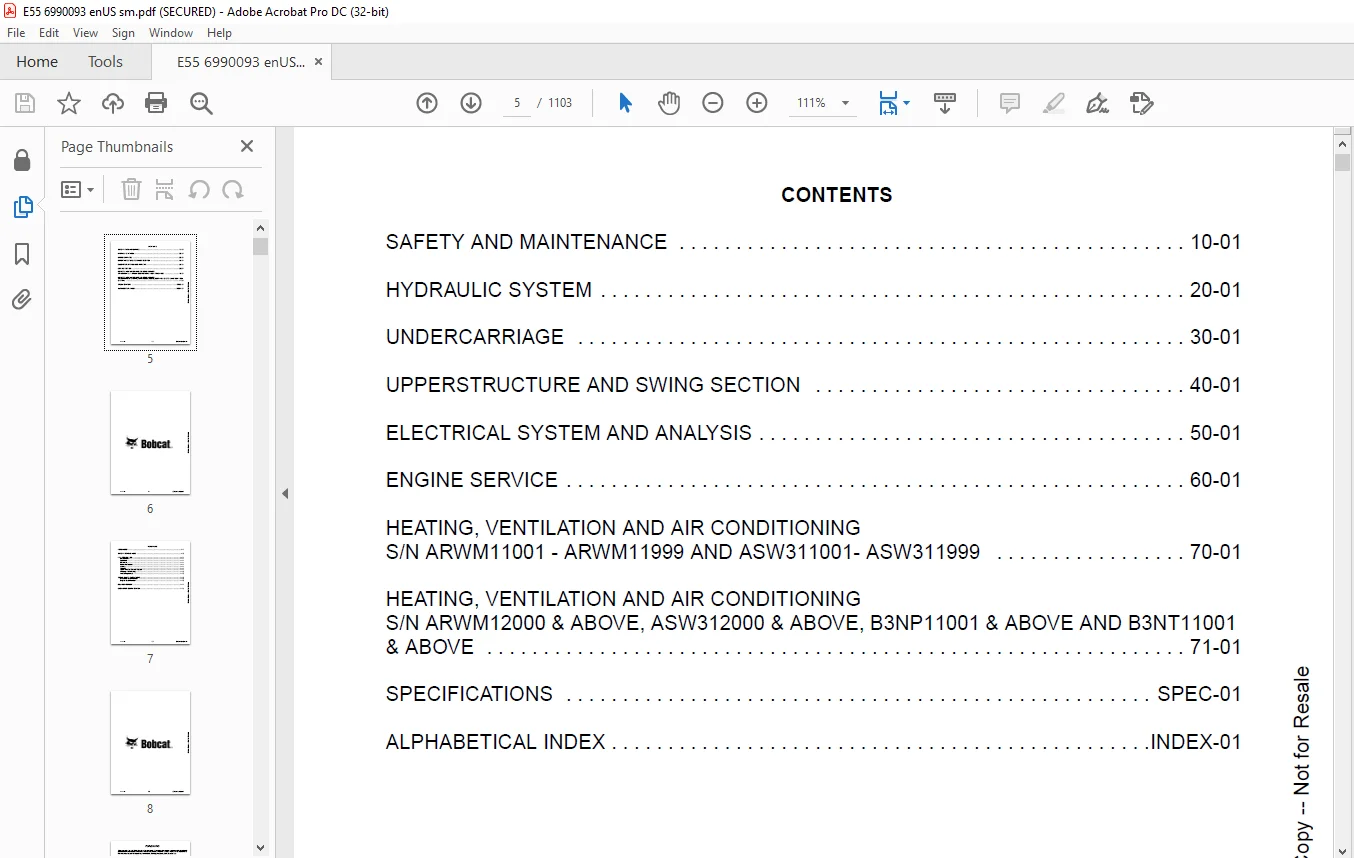
TABLE OF CONTENTS:
Bobcat E55 Compact Excavator Service Manual 6990093 (01-20) – PDF DOWNLOAD
MAINTENANCE SAFETY 3
CONTENTS 5
FOREWORD 7
FOREWORD 9
SAFETY INSTRUCTIONS 11
FIRE PREVENTION 13
Maintenance 13
Operation 13
Electrical 13
Hydraulic System 13
Fueling 13
Starting 13
Spark Arrester Exhaust System 13
Welding And Grinding 14
Fire Extinguishers 14
SERIAL NUMBER LOCATIONS 15
Excavator Serial Number 15
Engine Serial Number 15
DELIVERY REPORT 16
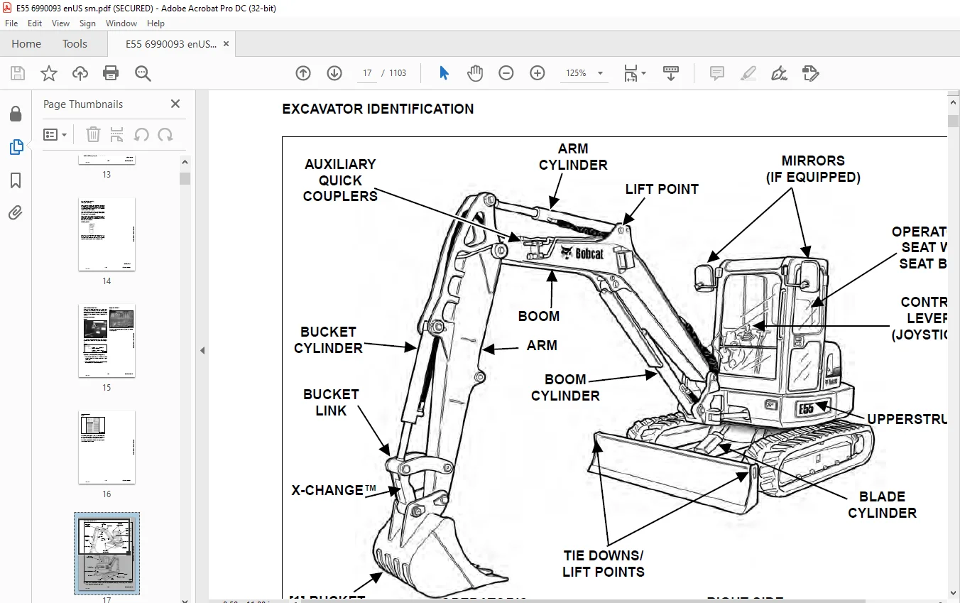
EXCAVATOR IDENTIFICATION 17
SAFETY AND MAINTENANCE 19
LIFTING AND BLOCKING THE EXCAVATOR 23
Procedure 23
LIFTING THE EXCAVATOR 25
Procedure 25
OPERATOR CAB (ROPS / TOPS) 27
Description 27
Cab Door 28
Front Window 29
Front Wiper 30
Window Washer Reservoir 30
Right Side Windows 31
TRANSPORTING THE EXCAVATOR ON A TRAILER 33
Loading And Unloading 33
Fastening 33
TAILGATE 35
Opening And Closing 35
Adjusting The Latch 35
RIGHT SIDE COVER 37
Opening And Closing 37
SERVICE SCHEDULE 39
Maintenance Intervals 39
AIR CLEANER SERVICE 41
Daily Check 41
Replacing The Filters Elements 41
CAB FILTERS (S/N ARWM11001 – ARWM11999 AND ASW311001- ASW311999) 43
Cleaning And Maintenance 43
CAB FILTERS (S/N ARWM12000 & ABOVE, ASW312000 & ABOVE, B3NP11001 & ABOVE AND B3NT11001 & ABOVE) 45
Cleaning And Maintenance 45
ENGINE COOLING SYSTEM 47
Cleaning 47
Checking Level 48
Removing And Replacing Coolant 49
FUEL SYSTEM 51
Fuel Specifications 51
Biodiesel Blend Fuel 51
Filling The Fuel Tank 52
Fuel Filters 53
Draining The Fuel Tank 53
Removing Air From The Fuel System 54
ENGINE LUBRICATION SYSTEM 55
Checking And Adding Engine Oil 55
Engine Oil Chart 55
Removing And Replacing Oil And Filter 56
HYDRAULIC SYSTEM 59
Checking And Adding Hydraulic Fluid 59
Hydraulic / Hydrostatic Fluid Chart 60
Removing And Replacing The Hydraulic Filters 60
Removing And Replacing The Hydraulic Fluid 62
LUBRICATING THE EXCAVATOR (EARLIER MODELS) 65
Lubrication Locations 65
LUBRICATING THE EXCAVATOR (LATER MODELS) 69
Lubrication Locations 69
PIVOT PINS 73
Inspection And Maintenance 73
TRAVEL MOTOR 75
Checking And Adding Oil 75
Removing And Replacing Oil 75
SPARK ARRESTER MUFFLER 77
Cleaning Procedure 77
EMERGENCY EXIT 79
Right Side Rear Window 79
Front Window 79
SEAT BELT 81
Inspection And Maintenance 81
CONTROL CONSOLE LOCKOUTS 83
Inspection And Maintenance 83
TOWING THE EXCAVATOR 85
Procedure 85
REMOTE START TOOL KIT – MEL1563 87
Remote Start Tool – MEL1563 87
Service Tool Harness Control – MEL1565 88
Service Tool Harness Communicator – MEL1566 89
REMOTE START TOOL (SERVICE TOOL) KIT – 7217666 91
Description 91
Remote Start Tool (Service Tool) – 7022042 92
Excavator Service Tool Harness – 6689747 93
Computer Service Tool Harness – 6689746 94
HYDRAULIC SYSTEM 95
HYDRAULIC / HYDROSTATIC SCHEMATICS 101
HYDRAULIC SYSTEM INFORMATION 109
Glossary Of Hydraulic / Hydrostatic Symbols 109
Troubleshooting The Hydraulic Circuit 112
Troubleshooting The Cylinder Circuit 113
Troubleshooting The Swing (Upperstructure Slew) Circuit 114
Troubleshooting The Travel Circuit 115
CYLINDER (BOOM) 117
Testing 117
Removal And Installation 119
Parts Identification 122
Disassembly 123
Assembly 126
CYLINDER (ARM) 131
Testing 131
Removal And Installation 133
Parts Identification 135
Disassembly 136
Assembly 138
CYLINDER (BOOM SWING) 143
Testing 143
Removal And Installation 145
Parts Identification 148
Disassembly 149
Assembly 151
CYLINDER (BUCKET) 155
Testing 155
Removal And Installation 157
Parts Identification 159
Disassembly 160
Assembly 162
CYLINDER (BLADE) 165
Testing 165
Removal And Installation 167
Parts Identification 168
Disassembly 169
Assembly 171
CYLINDER (CLAMP) 175
Testing 175
Removal And Installation 176
Parts Identification 178
Disassembly 179
Assembly 182
CYLINDER (ANGLE BLADE) 187
Testing 187
Removal And Installation 188
Parts Identification 190
Disassembly 191
Assembly 193
CYLINDER (EXTENDABLE ARM) 197
Testing 197
Parts Identification 199
Disassembly 200
Assembly 203
VALVE (MAIN RELIEF) 207
Testing And Adjusting 207
VALVE (PORT RELIEF) 209
Testing And Adjusting Port Relief Valve Pressure 209
VALVE (CROSS PORT RELIEF) 211
Testing And Adjusting 211
Removal And Installation 214
VALVE (PRESSURE REDUCING) 215
Testing And Adjusting 215
HYDRAULIC CONTROL VALVE 217
Description 217
Removal And Installation 217
Parts Identification 221
Disassembly And Assembly 222
Inlet Valve Section Disassembly And Assembly 226
Boom Swing Valve Section Disassembly And Assembly 230
Slew Valve Section Disassembly And Assembly 233
Blade Valve Section Disassembly And Assembly 237
Right And Left Travel Valve Section Disassembly And Assembly 241
Angle Blade, Boom, Auxiliary, Arm And Bucket Valve Section Disassembly And Assembly 243
HYDRAULIC PUMP 247
Hydraulic Pump Work Sheet 247
Pump Testing 250
Removal And Installation 259
Coupler Removal And Installation 260
Hydraulic Pump Startup 261
Torque Limiter Assembly Parts Identification 262
Torque Limiter Assembly Removal And Installation 263
Torque Limiter Valve Assembly Disassembly And Assembly 263
Pump Control Parts Identification 264
Pump Control Removal And Installation 265
Pump Control Disassembly And Assembly 265
Parts Identification 271
Disassembly And Assembly 272
MANIFOLD ASSEMBLY / ACCUMULATOR (WITHOUT ANGLE BLADE) 281
Description 281
Removal And Installation 281
Parts Identification 283
Disassembly And Assembly 284
MANIFOLD ASSEMBLY / ACCUMULATOR (WITH ANGLE BLADE) 291
Description 291
Removal And Installation 291
Parts Identification 293
Disassembly And Assembly 294
TRAVEL MOTOR 301
Removal And Installation 301
Parts Identification Hydraulic Motor 302
Parts Identification Gear Reduction Hub 303
Disassembly 304
Assembly 314
TRAVEL MOTOR (S/N ARWM14000 & ABOVE) 327
Removal And Installation 327
Parts Identification Hydraulic Motor 328
Parts Identification Gear Reduction Hub 329
Disassembly 330
Assembly 338
SWIVEL JOINT 347
Removal And Installation 347
Parts Identification Angle Blade Swivel (S/N ARWM11001 – ARWM12440, ASW311001 – ASW312584) 349
Parts Identification Angle Blade Swivel (S/N ARWM12441 – ARWM12554, ASW312585 & Above) 350
Parts Identification Angle Blade Swivel (S/N ARWM12555 & Above) 351
Parts Identification Straight Blade Swivel (S/N ARWM11001 – ARWM12440, ASW311001 – ASW312584) 352
Parts Identification Straight Blade Swivel (S/N ARWM12441 – ARWM12554, ASW312585 & Above) 353
Parts Identification Angle Blade Swivel (S/N ARWM12555 & Above) 354
Disassembly And Assembly 355
SWING MOTOR 357
Removal And Installation 357
Parts Identification 359
Disassembly And Assembly 360
SWING MOTOR (DRIVE CARRIER) 369
Removal And Installation 369
Parts Identification 370
Disassembly And Assembly 371
CONTROL PATTERN SELECTOR VALVE 377
Removal And Installation 377
Parts Identification 378
Disassembly And Assembly 379
RIGHT CONTROL LEVER (JOYSTICK) (S/N ARWM11001 – ARWM11999 AND ASW311001 – ASW311999) 381
Testing 381
Handle Removal And Installation 382
Joystick Assembly Removal And Installation 384
Parts Identification 385
Disassembly 386
Assembly 391
RIGHT CONTROL LEVER (JOYSTICK) (S/N ARWM12001 & ABOVE, ASW312001 & ABOVE, B3NP11001 & ABOVE AND B3NT11001 & ABOVE) 397
Testing 397
Handle Removal And Installation 398
Joystick Assembly Removal And Installation 400
Parts Identification 401
Disassembly 402
Assembly 406
LEFT CONTROL LEVER (JOYSTICK) (ARWM11001 – ARWM11999 AND ASW311001 – ASW311999) 411
Testing 411
Handle Removal And Installation 412
Joystick Assembly Removal And Installation 414
Parts Identification 415
Disassembly 416
Assembly 421
LEFT CONTROL LEVER (JOYSTICK) (ARWM12001 & ABOVE, ASW312001 & ABOVE, B3NP11001 & ABOVE AND B3NT11001 & ABOVE) 427
Testing 427
Handle Removal And Installation 428
Joystick Assembly Removal And Installation 430
Parts Identification 431
Disassembly 432
Assembly 436
HYDRAULIC FILTER MOUNT 441
Removal And Installation 441
HYDRAULIC RESERVOIR 443
Removal And Installation 443
OIL COOLER 445
Removal And Installation 445
DIRECT TO TANK VALVE 447
Removal And Installation 447
BLADE CONTROL LEVER 449
Handle Removal And Installation 449
Removal And Installation 451
Parts Identification 453
Disassembly And Assembly 454
CASE DRAIN FILTER MOUNT 459
Removal And Installation 459
TRAVEL CONTROL VALVE 461
Removal And Installation 461
Parts Identification 462
Disassembly And Assembly 463
REMOVING AIR FROM THE HYDRAULIC SYSTEM 469
Procedure 469
MANIFOLD (HYDRAULIC X-CHANGE) (EARLIER MODELS) 471
Removal And Installation 471
Parts Identification 472
Disassembly And Assembly 473
MANIFOLD (HYDRAULIC X-CHANGE) (LATER MODELS) 477
Removal And Installation 477
Parts Identification 478
Disassembly And Assembly 479
MANIFOLD (PIN GRABBER) 485
Removal And Installation 485
Parts Identification 486
Disassembly And Assembly 487
SECONDARY AUXILIARY VALVE (EARLIER MODELS) 489
Removal And Installation 489
Parts Identification 491
Disassembly And Assembly 492
SECONDARY AUXILIARY VALVE (LATER MODELS) 497
Removal And Installation 497
Parts Identification 499
Disassembly And Assembly 500
VALVE (BOOM LOCK) 503
Removal And Installation 503
VALVE (ARM LOCK) 505
Removal And Installation 505
UNDERCARRIAGE 507
BLADE 509
Removal And Installation 509
BLADE (ANGLE) 511
Removal And Installation 511
Cutting Edge Removal And Installation 512
TRACK UNDERCARRIAGE COMPONENTS (RUBBER TRACK) 513
Description 513
Track Lug Height 513
Checking Tension 514
Adjusting Tension 515
Track Removal And Installation 517
Idler Removal And Installation 518
Idler Parts Identification 519
Idler Disassembly 520
Idler Assembly 522
Track Tensioner Removal And Installation 525
Track Tensioner Parts Identification 526
Track Tensioner Disassembly And Assembly 527
Roller Removal And Installation 529
Sprocket Removal And Installation 530
TRACK UNDERCARRIAGE COMPONENTS (STEEL TRACK) 531
Description 531
Checking Tension 532
Adjusting Tension 533
Track Removal 535
Track Installation 538
Idler Removal And Installation 540
Idler Parts Identification 541
Idler Disassembly 542
Idler Assembly 544
Track Tensioner Removal And Installation 547
Track Tensioner Parts Identification 548
Track Tensioner Disassembly And Assembly 549
Roller Removal And Installation 551
Sprocket Removal And Installation 552
Guide Plate Removal And Installation 552
TRACK MAINTENANCE 553
Track Damage Identification 553
SWING CIRCLE GEAR 565
Swing Bearing Removal 565
Swing Bearing Installation 566
UPPERSTRUCTURE AND SWING SECTION 567
UPPERSTRUCTURE 571
Removal 571
Installation 573
ROPS CANOPY 575
Removal And Installation 575
CAB 579
Removal And Installation 579
Door Removal And Installation 582
Front Window Removal And Installation (Earlier Models) 583
Front Window Removal And Installation (Later Models) 584
Front Window Disassembly And Assembly (Later Models) 585
Front Window Adjustment (Later Models) 587
Right Side Rear Sliding Window Removal And Installation 589
Right Side Front Sliding Window Removal And Installation 589
Right Side Front And Rear Sliding Window Weather Strip Removal And Installation 590
Right Side Front And Rear Sliding Window Wiper Strip Removal And Installation 590
Glass Removal 591
Glass Installation 592
SEAT 599
Removal And Installation 599
Seat Mount Removal And Installation 600
RIGHT CONSOLE (S/N ARWM11001 – ARWM11999 AND ASW311001 – ASW311999) 601
Console Cover Removal And Installation 601
RIGHT CONSOLE (S/N ARWM12000 & ABOVE, ASW312000 & ABOVE, B3NP11001 & ABOVE AND B3NT11001 & ABOVE) 607
Console Cover Removal And Installation 607
LEFT CONSOLE 613
Lower Console Cover Removal And Installation 613
Upper Console Cover Removal And Installation 614
Compression Spring Removal And Installation 617
Lock Lever Removal And Installation 619
Console Removal And Installation 619
LEFT UPPERSTRUCTURE COVER 621
Removal And Installation 621
RIGHT UPPERSTRUCTURE COVER 623
Removal And Installation 623
COUNTERWEIGHT 625
Removal And Installation 625
COUNTERWEIGHT (LOWER) 629
Removal And Installation 629
TRAVEL LEVERS AND PEDALS 631
Removal And Installation 631
Disassembly And Assembly 632
FLOOR MAT 633
Removal And Installation 633
FUEL TANK 635
Removal And Installation 635
Fuel Tank Fitting Removal And Installation 636
Removal And Installation (Cab Equipped Excavator) 636
HORN 637
Removal And Installation 637
SWING FRAME 639
Removal And Installation 639
Boom Swing Frame Hose Routing 642
Bushing Removal 643
Bushing Installation 644
BOOM 645
Removal And Installation 645
ARM (STANDARD AND LONG) 647
Removal And Installation 647
Arm To Boom Bushing Removal And Installation 648
Arm To Bucket And Bucket Link Bushing Removal And Installation 649
ARM (EXTENDABLE) 651
Removal And Installation 651
Arm To Boom Bushing Removal And Installation 652
Arm To Bucket Bushing Removal And Installation 653
Disassembly And Assembly 654
Shimming Procedure 661
BUCKET 663
Bucket Teeth Removal And Installation 663
Bucket Side Cutting Edge Removal And Installation 664
CLAMP 665
Removal And Installation 665
TAILGATE 667
Removal And Installation 667
Latch Removal And Installation 668
X-CHANGE 669
Removal And Installation 669
Disassembly 671
Assembly 672
X-CHANGE (HYDRAULIC) EARLIER MODELS 675
Removal And Installation 675
Parts Identification 677
Disassembly 678
Assembly 683
Expansion Plug Installation 691
X-CHANGE (HYDRAULIC) LATER MODEL 693
Removal And Installation 693
Parts Identification 695
Disassembly 696
Assembly 702
Expansion Plug Installation 710
QUICK COUPLER (KLAC™ SYSTEM) 711
Troubleshooting 711
Daily Inspection 711
Removal And Installation 712
Parts Identification 714
Disassembly 715
Assembly 717
QUICK COUPLER (LEHNHOFF® SYSTEM) 719
Troubleshooting 719
Daily Inspection 719
Removal (MS03 And MS08) 720
Installation (MS03 And MS08) 721
Parts Identification (MS03) 722
Disassembly And Assembly (MS03) 723
Parts Identification (MS08) 724
Disassembly (MS08) 725
Assembly (MS08) 728
QUICK COUPLER (PIN GRABBER) 733
Troubleshooting 733
Daily Inspection 734
Removal And Installation 735
Parts Identification 736
Disassembly And Assembly 737
RIGHT SIDE COVER (EARLIER MODEL) 739
Removal And Installation 739
Latch Removal And Installation 740
Latch Adjustment 741
RIGHT SIDE COVER (LATER MODEL) 743
Removal And Installation 743
Latch Removal And Installation 743
Adjustment 744
TOOL BOX 745
Removal And Installation 745
ELECTRICAL SYSTEM AND ANALYSIS 747
ELECTRICAL SCHEMATICS 751
ELECTRICAL SYSTEM INFORMATION 762
Troubleshooting Chart 762
Description 763
Fuse And Relay Location / Identification 763
Shut-Off Switch (If Equipped) 765
BATTERY 766
Servicing 766
Removal And Installation 767
Using A Booster Battery (Jump Starting) 768
ALTERNATOR 770
Belt Adjustment 770
Belt Replacement 770
Charging System Inspection 772
Alternator Voltage Testing 773
Low Voltage Testing 773
High Voltage Testing 774
Removal And Installation 775
Parts Identification 776
STARTER 778
Testing 778
Removal And Installation 779
Parts Identification 780
LIGHTS 782
Removal And Installation 782
Boom Light Removal And Installation 783
Boom Light Bulb Replacement 783
MAGNETIC LOCKOUT SENSOR 784
Removal And Installation 784
FUEL LEVEL SENDER 786
Removal And Installation 786
Testing 787
DIAGNOSTIC SERVICE CODES (S/N ARWM11001 – ARWM11999 AND ASW311001- ASW311999) 788
Service Codes List 788
DIAGNOSTIC SERVICE CODES (S/N ARWM12000 & ABOVE, ASW312000 & ABOVE, B3NP11001 & ABOVE AND B3NT11001 & ABOVE) 790
Viewing Service Codes 790
Number Codes List 791
DELUXE INSTRUMENT PANEL SETUP (S/N ARWM11001 – ARWM11999 AND ASW311001- ASW311999) 794
Passwords 794
Password Entry (For Starting And Operating The Machine) 794
Changing The Operator Password 794
Password Lockout Feature 795
Job Clock 795
RPM 795
CONTROL PANEL SETUP (S/N ARWM12000 & ABOVE, ASW312000 & ABOVE, B3NP11001 & ABOVE AND B3NT11001 & ABOVE) 796
Panel Setup (Deluxe Instrument Panel) 796
Password Setup (Keyless Start Panel) 802
Password Setup (Deluxe Instrument Panel) 803
Maintenance Clock 805
INSTRUMENT PANEL / CONTROLLER (S/N ARWM11001 – ARWM11999 AND ASW311001 – ASW311999) 808
Removal And Installation 808
INSTRUMENT PANEL (S/N ARWM12000 & ABOVE, ASW312000 & ABOVE, B3NP11001 & ABOVE AND B3NT11001 & ABOVE) 810
Removal And Installation 810
CONTROLLER (S/N ARWM12000 & ABOVE, ASW312000 & ABOVE, B3NP11001 & ABOVE AND B3NT11001 & ABOVE) (GATEWAY AND AUXILIARY) 812
Description 812
Gateway Controller Removal And Installation 812
Auxiliary Controller Removal And Installation 813
KEY SWITCH 814
Removal And Installation 814
WIPER MOTOR 816
Removal And Installation 816
MOTION ALARM SYSTEM 818
Description 818
Inspecting 818
Adjusting Switch Position 819
SERVICE PC (LAPTOP COMPUTER) 820
Connecting The Remote Start Tool 820
Connecting Remote Start Tool (Service Tool) 820
Operation 821
SHUT-OFF SWITCH 822
Description 822
Removal And Installation 823
TRAVEL MOTOR AUTO-SHIFT 826
Auto-Shift Drive System (If Equipped) 826
Troubleshooting 827
AUTO IDLE PRESSURE SENSOR 830
Description 830
Removal And Installation 831
BOBCAT MACHINE IQ WIRELESS COMMUNICATIONS 832
Description 832
Controller Removal And Installation 832
Antenna Removal And Installation 834
Procedure 836
ENGINE SERVICE 838
ENGINE INFORMATION 842
Description 842
Specifications 843
Crankshaft Re-Grind Data 849
Torque For Kubota® Metric Bolts 850
Troubleshooting 851
Removal And Installation 852
Compression-Checking 862
ENGINE SPEED CONTROL 864
Removal And Installation 864
Auto Idle Description 865
Auto Idle Controller Removal And Installation 866
Calibration 867
Actuator Removal And Installation (Earlier Model) 870
Actuator Removal And Installation (Later Model) 873
MUFFLER 874
Removal And Installation 874
AIR CLEANER 876
Housing Removal And Installation 876
ENGINE COOLING SYSTEM 878
Radiator Removal And Installation 878
Fan Removal And Installation 882
Water Pump Removal And Installation 884
Water Pump Disassembly And Assembly 885
Thermostat Housing Removal And Installation 886
Thermostat – Checking 887
LUBRICATION SYSTEM 888
Oil Pan Removal And Installation 888
Oil Pump Removal And Installation 889
Oil Pump Inspection 889
Engine Oil Pressure – Testing 890
FUEL SYSTEM 892
Fuel Shutoff Solenoid – Checking 892
Fuel Shut-off Solenoid Removal And Installation 893
Fuel Injection Pump – Checking 894
Fuel Injection Pump Removal And Installation 895
Fuel Injection Pump – Timing 898
Fuel Camshaft Removal And Installation 900
Fuel Camshaft Governor 901
Fuel Injector Removal And Installation 902
Fuel Injector Nozzle Pressure – Checking 904
Nozzle Spray Condition 905
Valve Seat Tightness 905
CYLINDER HEAD 906
Glow Plugs – Testing 906
Glow Plugs Removal And Installation 907
Valve Clearance Adjustment 908
Valve Timing – Checking 908
Cylinder Head Removal And Installation 909
Cylinder Head Disassembly And Assembly 912
Cylinder Head – Servicing 913
Cylinder Head Top Clearance 913
Valve Guide – Checking 914
Valve Guide Removal And Installation 915
Reconditioning The Valve And Valve Seat 916
Valve Spring 917
Valve Tappets 918
Rocker Arm And Shaft – Checking 919
Push Rod Alignment – Checking 919
CRANKSHAFT AND PISTONS 920
Piston And Connecting Rod Removal And Installation 920
Piston And Connecting Rod – Servicing 922
Cylinder Bore – Checking 924
Connecting Rod Alignment 925
Crankshaft Gear Removal And Installation 926
Crankshaft And Bearings Removal And Installation 927
Crankshaft And Bearings – Servicing 930
CAMSHAFT AND TIMING GEARS 934
Timing Gearcase Cover Removal And Installation 934
Timing Gears Backlash – Checking 937
Idle Gear And Camshaft Removal And Installation 938
Camshaft – Servicing 940
Idle Gear And Shaft – Servicing 941
TURBOCHARGER 942
Description 942
Testing 942
Removal And Installation 943
FLYWHEEL AND HOUSING 946
Hydraulic Pump Coupler Removal And Installation 946
Flywheel Removal And Installation 948
Flywheel Ring Gear 948
FLYWHEEL RPM SENSOR 950
Description 950
Removal 950
Installation 950
HEATING, VENTILATION AND AIR CONDITIONING S/N ARWM11001 – ARWM11999 AND ASW311001- ASW311999 952
AIR CONDITIONING SYSTEM FLOW 954
Description 954
Chart 955
Components 956
Safety Equipment 960
REGULAR MAINTENANCE 962
Cab Filters 962
Air Conditioning Compressor Belt Adjustment 963
Air Conditioning Compressor Belt Replacement 963
Condenser 964
Air Conditioning Lubrication 964
Evaporator / Heater Coil 964
Air Conditioning Service Chart 965
TROUBLESHOOTING 966
Blower Motor Does Not Operate 966
Blower Motor Operates Normally, But Air Flow Is Insufficient 966
Insufficient Cooling Although Air Flow And Compressor Operation Are Normal 966
The Compressor Operates Improperly Or Not At All 966
Gauge Pressure Related Troubleshooting 967
Temperature / Pressure Chart 968
Poor A/C Performance 969
HVAC Repair And Leaks 969
Electrical System 970
Engine Coolant Bypassing The Heater Valve 972
SYSTEM CHARGING AND RECLAMATION 974
Refrigerant Identification 974
Reclamation And Charging With Recovery / Charging Unit 976
COMPRESSOR 978
Removal And Installation 978
Oil 980
Oil Check 981
CONDENSER 984
Removal And Installation 984
RECEIVER / DRIER 986
Receiver / Drier Removal And Installation 986
Pressure Relief Valve Removal And Installation 987
Pressure Switch Removal And Installation 987
EVAPORATOR / HEATER UNIT 988
Removal And Installation 988
THERMOSTAT 990
Description 990
Removal And Installation 991
EXPANSION VALVE 994
Removal And Installation 994
EVAPORATOR COIL 996
Removal And Installation 996
HEATER COIL 998
Removal And Installation 998
BLOWER FAN 1000
Removal And Installation 1000
HEATER VALVE 1002
Removal And Installation 1002
HVAC DUCT 1004
Removal And Installation 1004
HEATING, VENTILATION AND AIR CONDITIONING S/N ARWM12000 & ABOVE, ASW312000 & ABOVE, B3NP11001 & ABOVE AND B3NT11001 & ABOVE 1006
AIR CONDITIONING SYSTEM FLOW 1008
Description 1008
Chart 1009
Components 1010
Safety Equipment 1014
REGULAR MAINTENANCE 1016
Cab Filters 1016
Air Conditioning Compressor Belt Adjustment 1017
Air Conditioning Compressor Belt Replacement 1017
Condenser 1018
Air Conditioning Lubrication 1018
Evaporator / Heater Coil 1018
Air Conditioning Service Chart 1020
TROUBLESHOOTING 1022
Blower Motor Does Not Operate 1022
Blower Motor Operates Normally, But Air Flow Is Insufficient 1022
Insufficient Cooling Although Air Flow And Compressor Operation Are Normal 1022
The Compressor Operates Improperly Or Not At All 1022
Gauge Pressure Related Troubleshooting 1023
Temperature / Pressure Chart 1024
Poor A/C Performance 1025
HVAC Repair And Leaks 1025
Electrical System 1026
Engine Coolant Bypassing The Heater Valve 1028
SYSTEM CHARGING AND RECLAMATION 1030
Refrigerant Identification 1030
Reclamation And Charging With Recovery / Charging Unit 1032
COMPRESSOR 1034
Removal And Installation 1034
Oil 1036
Oil Check 1037
CONDENSER 1040
Removal And Installation 1040
RECEIVER / DRIER 1042
Receiver / Drier Removal And Installation 1042
Pressure Relief Valve Removal And Installation 1043
Pressure Switch Removal And Installation 1043
EVAPORATOR / HEATER UNIT 1044
Removal And Installation 1044
THERMOSTAT 1046
Description 1046
Removal And Installation 1047
EXPANSION VALVE 1050
Removal And Installation 1050
EVAPORATOR COIL 1052
Removal And Installation 1052
HEATER COIL 1054
Removal And Installation 1054
BLOWER FAN 1056
Removal And Installation 1056
HEATER VALVE 1058
Removal And Installation 1058
HVAC DUCT 1060
Removal And Installation 1060
SPECIFICATIONS 1062
EXCAVATOR SPECIFICATIONS 1064
Machine Dimensions 1064
Machine Dimensions – Standard Arm 1065
Machine Dimensions – Extendable Arm 1066
Machine Dimensions – Angle Blade 1067
Rated Lift Capacity (Standard Arm) 1068
Rated Lift Capacity (Extendable Arm) 1069
Performance 1070
Controls 1070
Engine 1071
Hydraulic System 1072
Hydraulic Cylinders 1073
Hydraulic Cycle Times 1073
Drive System 1073
Slew System 1073
Undercarriage 1073
Electrical 1074
Capacities 1074
Tracks 1074
Ground Pressure 1074
TORQUE SPECIFICATION FOR BOLTS 1076
Torque For General SAE Bolts 1076
Torque For General Metric Bolts 1077
HYDRAULIC CONNECTION SPECIFICATIONS 1078
O-ring Face Seal Connection 1078
Straight Thread O-ring Fitting 1078
Tubelines And Hoses 1079
Flare Fitting 1079
O-ring Flare Fitting 1080
Port Seal Fitting 1082
Push To Connect Fittings 1083
HYDRAULIC FLUID SPECIFICATIONS 1086
Specifications 1086
CONVERSIONS 1088
Decimal And Millimeter Equivalent Chart 1088
U S To Metric Conversion Chart 1089
SERVICE TOOLS REQUIRED 1090
Remote Start Tools 1090
Hydraulic Tools 1091
Engine Tools 1094
Electrical Tools 1096
General Tools 1096
HVAC Tools 1097
ALPHABETICAL INDEX 1098
SERVICE SCHEDULE SYMBOLS 1102
Contact us: [email protected]
https://vimeo.com/841821910?share=copy
PLEASE NOTE:
- This is the SAME manual used by the dealers to troubleshoot any faults in your vehicle. This can be yours in 2 minutes after the payment is made.
- Contact us at [email protected] should you have any queries before your purchase or that you need any other service / repair / parts operators manual.
S.M