Bobcat E145 Compact Excavator Service Manual SN B4WU11001 & Above – PDF DOWNLOAD
$35.95
Bobcat E145 Compact Excavator Service Manual SN B4WU11001 & Above – PDF DOWNLOAD
S/N B4WU11001 & Above
Description
Bobcat E145 Compact Excavator Service Manual SN B4WU11001 & Above – PDF DOWNLOAD
FILE DETAILS:
Bobcat E145 Compact Excavator Service Manual SN B4WU11001 & Above – PDF DOWNLOAD
Language : English
Pages :1466
Downloadable : Yes
File Type : PDF
DESCRIPTION:
S/N B4WU11001 & Above
Bobcat E145 Compact Excavator Service Manual SN B4WU11001 & Above – PDF DOWNLOAD
FOREWORD
This manual is for the Bobcat excavator mechanic. It provides necessary servicing and adjustment procedures for the Bobcat excavator and its component parts and systems. Refer to the Operation & Maintenance Manual for operating instructions, starting procedure, daily checks, etc.
SAFETY INSTRUCTIONS
Instructions are necessary before operating or servicing machine. Read and understand the Operation & Maintenance Manual, Operator’s Handbook and signs (decals) on machine. Follow warnings and instructions in the manuals when making repairs, adjustments or servicing. Check for correct function after adjustments, repairs or service. Untrained operators and failure to follow instructions can cause injury or death.
The following publications provide information on the safe use and maintenance of the Bobcat machine and attachments:
- The Delivery Report is used to assure that complete instructions have been given to the new owner and that the machine is in safe operating condition.
- The Operation & Maintenance Manual delivered with the machine or attachment contains operating information as well as routine maintenance and service procedures. It is a part of the machine and can be stored in a container provided on the machine. Replacement Operation & Maintenance Manuals can be ordered from your Bobcat dealer.
- Machine signs (decals) instruct on the safe operation and care of your Bobcat machine or attachment. The signs and their locations are shown in the Operation & Maintenance Manual. Replacement signs are available from your Bobcat dealer.
- An Operator’s Handbook fastened to the operator cab. It’s brief instructions are convenient to the operator. The handbook is available from your dealer in an English edition or one of many other languages. See your Bobcat dealer for more information on translated versions.
- The AEM Safety Manual delivered with the machine gives general safety information.
- The Service Manual and Parts Manual are available from your dealer for use by mechanics to do shoptype service and repair work.
IMAGES PREVIEW OF THE MANUAL:
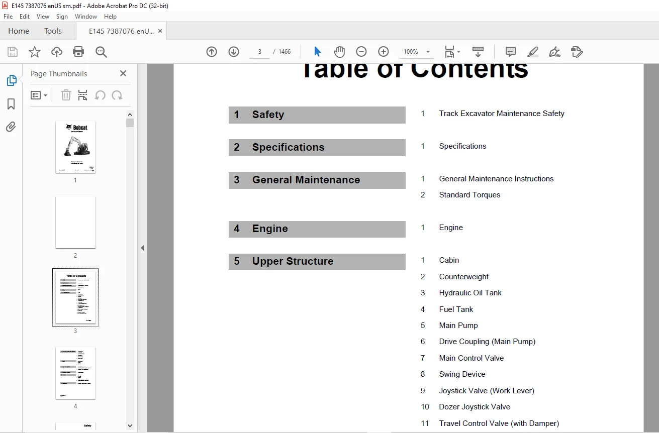
TABLE OF CONTENTS:
Bobcat E145 Compact Excavator Service Manual SN B4WU11001 & Above – PDF DOWNLOAD
Table of Contents 3
Safety 5
Track Excavator Maintenance Safety 7
Safety Instructions 11
Safety Messages 11
General 13
Safe Operation is Operator’s Responsibility 13
Know Your Machine 13
Proper Work Tools and Attachments 14
Pressurized Fluids 14
Flying or Falling Objects 15
Personal Protective Equipment (PPE) 16
Correction of Machine Problems 16
Crushing and Cutting 16
Hot Coolant and Oils – Burn Prevention 17
Fire and Explosion Prevention 18
Fire Extinguisher and First-aid Kit (Emergency Medical Kit) 21
Electrical System and Electrical Shock 22
Roll-over Protective Structure (ROPS) 22
Transportation 26
Obey State and Local Over-the-Road Regulations 26
Loading and Unloading 26
Transporting Machine 27
Operation 28
Before Engine Starting 28
Work Site 29
Entering and Exiting 30
Cleaning 31
Operator Station 31
Seat Belt 32
Visibility Information 33
Boost Starting or Charging Engine Batteries 35
Starting Engine 36
Swinging or Traveling 37
Lifting and Digging 39
Operation on Slopes 40
Towing 41
Attachment 42
Engine Stop 43
Parking Machine 43
Preservation/Storing Machine 44
Maintenance 46
Cleaning 48
Fire and Explosion Prevention 48
Burn Prevention 49
Lock Inspection Covers 49
Working on Machine 50
Track Tension Adjustments 51
Supports and Blocking for Work Equipment 51
High-pressure Lines, Tubes and Hoses 52
Battery 53
Environment and Circumstances 55
Work Site Areas Requiring Extra Caution 55
High-voltage Cables 56
Underground Operation 57
Working in Water 57
Working in Contaminated Environment 57
Exhaust Ventilation 58
Asbestos Information 58
Silica Dust Information 59
Disposal of Hazardous Materials 59
Sound 59
Vibration Information 60
Specifications 63
Specifications 65
Safety Instructions 69
General Description 69
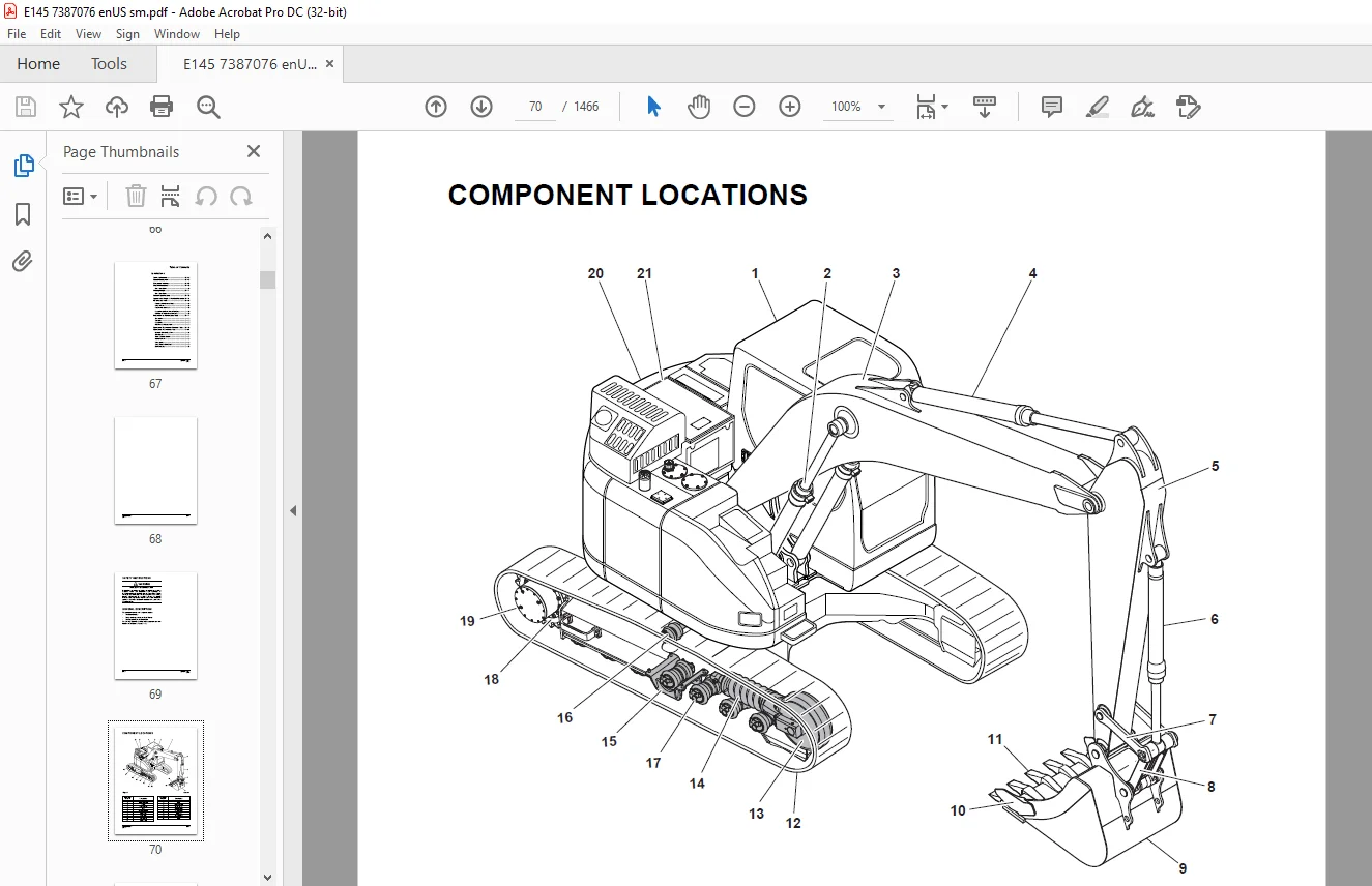
Component Locations 70
Overall Dimensions 74
One – Piece Boom 74
Working Range 75
One – Piece Boom 75
General Specifications 77
Approximate Weight of Workload Materials 78
Performance Tests 80
Purpose of Performance Tests 80
Kinds of Tests 80
Performance Standards 80
Precautions for Evaluation of Test Data 80
Definition of “Performance Standard” 80
Preparation for Performance Tests 81
The Machine 81
Test Area 81
Precautions 81
Make Precise Measurement 81
Operational Performance Standard Table 82
Operational Performance Test 85
Hydraulic Cylinder Cycle Time 85
Travel Speed 87
Track Revolution Speed 88
Mistrack Check 90
Swing Speed 92
Swing Function Drift Check 93
Cylinder Creep 94
General Maintenance 97
General Maintenance Instructions 99
Safety Instructions 103
Welding Precautions and Instructions 104
Hydraulic System – General Precautions 105
Maintenance Service and Repair Procedure 107
General Precautions 107
Hydraulic System Cleanliness and Oil Leaks 108
Maintenance Precautions for Hydraulic System Service 108
Oil Leakage Precautions 109
Cleaning and Inspection 110
General Instructions 110
Bearing Inspection 111
Standard Torques 119
Safety Instructions 123
Torque Values for Standard Metric Fasteners 124
Torque Values for Standard U S Fasteners 125
Type 8 Phosphate Coated Hardware 127
Torque Values for Hose Clamps 128
ORFS Swivel Nut Recommended Torque 128
Torque Values for Split Flanges 129
Torque Wrench Extension Tools 130
Torque Multiplication 130
Other Uses for Torque Wrench Extension Tools 131
Tightening Torque Specifications (Metric) 132
Engine 135
Engine 137
Safety Instructions 143
Overview 144
General Information 145
Major Component Location 145
Engine Identification 150
Engine Lifting 152
Maintenance and Storage 154
Engine Specification 157
General Specification 157
Engine Performance Curves 158
Basic Engine 159
Cylinder Block 159
Cylinder Head 161
Valve Mechanism Cover 173
Crankcase Breather 178
Flywheel and Flywheel Housing 182
Actuating System 194
Pistons, Rings, and Connecting Rods 194
Crankshaft 209
Gears and Timing Gear Case 228
Camshaft 251
Rocker Shaft 261
Lubricant System 272
Overview 272
Engine Oil Pump 274
Engine Oil Filter 278
Engine Oil Pan 280
Engine Oil Pressure – Test 288
Excessive Bearing Wear – Inspect 288
Excessive Engine Oil Consumption – Inspect 289
Increased Engine Oil Temperature – Inspect 289
Cooling System 290
Overview 290
Water Pump 291
Water Temperature Regulator 296
Engine Oil Cooler 300
Piston Cooling Jets 306
Fuel System 308
Overview 308
High-pressure Fuel System 309
Water Separator & Pre Fuel Filter (Fuel Prefilter) 311
Main Fuel Filter 315
Fuel Injection Pump 317
Fuel Injection Lines 325
Fuel Injectors 337
Fuel System – Inspect 345
Air in Fuel – Test 346
Finding Top Center Position for No 1 Piston 348
Fuel Injection Timing – Check 349
Fuel Quality – Test 350
Fuel System – Prime 351
Cleanliness of Fuel System 352
Air Inlet and Exhaust System 354
Exhaust System 354
Clean Emissions Module (Diesel Oxidation Catalyst (DOC) and Selective Catalytic Reduction (SCR) System) 409
DEF Dosing Control System 412
Electrical System 433
Electrical Control System 433
Sensor Locations for the Engine 436
Sensor Locations for the Clean Emissions Module 441
Electronic Control Module (ECM) 441
Electric Component – Remove and Install 448
Upper Structure 479
Cabin 481
Safety Instructions 485
Cabin Identification 485
Roll-over Protective Structure (ROPS) 485
Removal 487
Installation 494
Completing work 494
Dimensions of Cabin Glass 495
Removal and Installation of Cabin Glass 499
Removal of Cabin Glass 499
Installation of Cabin Glass 501
Installation of Upper Door Glass 506
Installation of Upper Front Glass 506
Counterweight 507
Safety Instructions 511
General 512
Warning for Counterweight and Front Attachment Removal 512
Removal 514
Installation 515
Hydraulic Oil Tank 517
Safety Instructions 521
General 521
Specification 521
Parts List 522
Air Breather 524
Removal 525
Installation 532
Completing Work 533
Fuel Tank 535
Safety Instructions 539
General 539
Specification 539
Parts List 540
Removal 542
Installation 548
Completing Work 549
Main Pump 551
Safety Instructions 555
Axial Piston Pump 555
General Description 555
Specifications 556
Overview 558
Hydraulic Circuit 561
Parts List 562
Theory of Operation 564
Tools 566
Tightening Torque 567
Removal 568
Installation 578
Completing Work 578
Disassembly 579
Reassembly 583
Troubleshooting 587
Maintenance Instructions 589
Regulator 590
Parts List 590
Functional Explanation 592
Adjustment 599
Section View 602
Pilot Gear Pump 604
Specification 604
Parts List 605
Theory of Operation 606
Port and Hydraulic Circuit 606
Precaution 607
Drive Coupling (Main Pump) 609
Safety Instructions 613
General 613
Specification 613
Parts List 614
Section View 616
Tools 617
Disassembly 618
Reassembly 619
Main Control Valve 621
Safety Instructions 625
General 625
Specification 625
Overview 626
Parts List 632
Theory of Operation 634
Cautions for Operation 658
Precaution 659
Removal 660
Installation 676
Completing Work 676
Disassembly 677
Cautions on Disassembly 677
Sequence of Disassembly 678
Cleaning and Inspection 686
Cleaning 686
Inspection 686
Reassembly 687
Caution on Assembly 687
Sequence of Reassembly 688
Troubleshooting and Adjustment 698
Troubleshooting 698
Adjusting Relief Valve 700
Swing Device 703
Safety Instructions 707
General 707
Specification 707
Overview 708
Parts List 710
Theory of Operation 714
Cautions for Operation 722
Removal 725
Installation 731
Completing work 731
Precaution 732
Tools for Disassembly and Assembly 732
Tightening Torque 732
Disassembly 734
Swing Device 734
Swing Motor 735
1 Wind the wire rope around motor, Lift up the motor with a crane and clean the motor with cleaning oil After cleaning, dry with compressed air 735
2 Drain the oil out of the casing (1) 735
3 Point the end of the driveshaft downward and attach it on a disassembly table for easy disassembling Before disassembling make a match mark on motor casing (1) and valve casing (2) 735
4 Remove relief valve (37) from valve casing (2) 735
5 Remove RO plug (25) and remove spring (24) and plunger (23) from valve casing (2) 735
6 Remove RO plug (39) and remove reactionless valve (39) from valve casing (2) 736
7 Remove hex socket bolts (30, 31) and disassemble valve casing (2) from casing (1) When loosening bolts, the valve casing will be raised by brake springs 736
8 Remove brake springs (21) (22 ea) from the brake piston (20) 736
9 Disassemble brake piston (20) from casing (1) by using the special tool for removing the brake piston 736
10 After placing the motor horizontally, remove cylinder block (17) from driveshaft (3) 737
11 Remove piston assembly (9), retainer (8), spherical bushing (11), collar (12), washer (14) When taking out the cylinder block, be careful not to pull out roller (13) Be careful not to damage the sliding parts of the cylinder block (17), thrust 737
12 Pull out friction plate (18) (3 ea) and separation plate (19) (3 ea) from casing (1) 737
13 Remove O-ring (27, 29) from casing (1) 738
Swing Reduction Gear 740
Reassembly 744
Swing Motor 744
1 Place casing (1) on the work table 744
2 Insert oil seal (6) at the casing (1) with a tool 744
3 Insert the driveshaft (3), roller bearing (4) into casing (1) 744
4 Fix the casing (1) flat, and assemble the retaining ring (36) into the driveshaft (3) with a pair of pliers 745
5 Assemble shoe plate (7) to casing (1) 745
6 Insert roller (13) to cylinder block (17) 745
7 Assemble the retainer (8) with the piston assembly (9) to the cylinder block (17) 745
8 Insert cylinder block (17) to driveshaft (3) by aligning with the spline 746
9 Place casing (1) downward and assemble separation plate (19) and friction plate (18) in sequence 746
10 Mount O-ring (27, 29) to casing (1) 746
11 Assemble brake piston (20) to casing (1) If the brake piston is difficult to assemble because of the restriction of the O-ring; screw in two M8 bolts on the brake piston and tap them gently with plastic hammer 746
12 Assemble brake springs (21) (22 ea) into brake piston (20) 747
13 Assemble the O-ring (28) and the spring pin (26) into the casing (2) 747
14 Assemble of ball bearing (5) Insert it to valve casing (2) while tapping it lightly 747
15 Assemble valve plate (22) to valve casing (2) 747
16 Mount valve casing (2) to casing (1) and tighten hex socket bolts (30, 31) to specification 748
Swing Reduction Gear 749
Troubleshooting 754
General Instructions 754
Examination of Hydraulic Motor 754
1) Lock the swing and supply high-pressure oil to the motor, and normal drain quantity must be approximately 25 LPM or less 754
Troubleshooting 755
Maintenance Instructions 758
Replacement Standard of Worn Parts 758
Standard of Sliding Surface Correction 758
Joystick Valve (Work Lever) 759
Safety Instructions 763
General 763
Specifications 763
Overview 764
Parts List 766
Theory of Operation 768
Tools and Torques 769
Section View 770
Removal 772
Installation 777
Completing work 778
Tools and Torques 779
Disassembly 779
Reassembly 783
Dozer Joystick Valve (Option) 791
Safety Instructions 795
General 795
Specifications 795
Overview 796
Hydraulic Circuit 797
Parts List 798
Theory of Operation 799
Tools 801
Removal 802
Installation 806
Completing work 807
Disassembly 808
Reassembly 811
Travel Control Valve (with Damper) 817
Safety Instructions 821
General 822
Specification 822
Overview 823
Parts List 824
Theory of Operation 826
Tools and Torques 827
Section View 828
Removal 829
Installation 833
Completing Work 834
Disassembly 835
2 Remove set screw (29) from cam (26) 835
Reassembly 838
15 Install bellows 842
Troubleshooting 843
Solenoid Valve 845
Safety Instructions 849
General 849
Specification 849
Overview 850
Parts List 852
Theory of Operation 853
Disassembly and Reassembly 854
Troubleshooting 855
EPPR Valve (One or Two-way) 857
Safety Instructions 861
General 862
Specification 862
Overview 863
Hydraulic Circuit 864
Troubleshooting 864
Accumulator 865
Safety Instructions 869
General 869
Specifications 871
Gear Pump (Rotation) 873
Safety Instructions 877
General 877
Specification 877
Overview 878
Location 878
Parts List 879
Single Gear Pump 880
Disassembly 880
Reassembly 882
One Spool Valve (Rotating) 887
Safety Instructions 891
General 891
Specification 891
Overview 892
Theory of Operation 893
Disassembly and Assembly 895
General Cautions 895
Replacement of Spool 896
Replacement of Main Relief Valve 898
Replacement of Overload Relief Valve 899
Replacement of Sub-Block 901
Lower Structure and Chassis 903
Swing Bearing 905
Safety Instructions 909
General 910
General Description 910
Parts List 910
Maintenance Guidelines 911
Disassembly 912
Reassembly 914
Center Joint 915
Safety Instructions 919
General 919
General Description 919
Overview 920
Parts List 921
Section View 922
Removal 923
Installation 928
Completing Work 928
Disassembly 929
Reassembly 932
Troubleshooting, Testing and Adjustment 934
Inspection 934
Testing 934
Center Joint (Dozer) 935
Safety Instructions 939
General 939
General Description 939
Overview 940
Parts List 942
Section View 944
Removal 945
Installation 950
Completing Work 950
Disassembly 951
Reassembly 953
Troubleshooting, Testing and Adjustment 955
Inspection 955
Testing 955
Travel Device 957
Safety Instructions 961
General 961
Specification 961
Overview 962
Parts List 964
Theory of Operation 968
Cautions for Operation 976
Precaution 980
Tools List for Disassembly and Reassembly 980
Removal 981
Installation 987
Completing Work 987
Section View 988
Disassembly 990
General Precautions 990
Disassembly Procedure 991
Reassembly 1003
General Precautions 1003
Reassembly Procedure 1003
Performance Test 1014
Summary of Seal Information 1015
Troubleshooting 1016
Track Assembly 1019
Safety Instructions 1023
General 1023
Track Tension 1024
Track Shoes and Links 1026
Parts List 1026
Track Removal 1027
Track Installation 1029
Wear Limits and Tolerances 1030
Sprocket 1032
Wear Limits and Tolerances 1032
Front Idler 1033
Overview 1033
Parts List 1034
Front Idler Disassembly 1035
Front Idler Reassembly 1036
Wear Limits and Tolerances 1038
Upper Roller 1039
Overview 1039
Parts List 1040
Upper Roller Removal 1041
Upper Roller Disassembly 1041
Upper Roller Reassembly 1043
Wear Limits and Tolerances 1044
Lower Roller 1045
Overview 1045
Parts List 1046
Lower Roller Removal 1047
Lower Roller Installation 1047
Lower Roller Disassembly 1048
Lower Roller Reassembly 1049
Wear Limits and Tolerances 1050
Track Adjuster 1052
Parts List 1052
Disassembly 1053
Assembly 1054
Dozer System 1057
Safety Instructions 1061
General Description 1062
Hydraulic Circuit 1063
Front 1065
Boom and Arm 1067
Safety Instructions 1071
Specifications 1072
One – Piece Boom 1072
Removal 1074
Arm Removal 1074
Boom Removal 1076
Installation 1077
Arm Installation 1077
Boom Installation 1077
Completing Work 1077
Bucket 1079
Safety Instructions 1083
Bucket Tooth Inspection and Replacement 1084
Bucket O-ring Replacement 1085
Installation 1086
Bucket Detaching and Reversal 1087
Detaching 1087
Reversal 1087
Cylinders 1089
Safety Instructions 1093
General 1093
General Description 1093
Specification 1093
Parts List 1094
Theory of Operation 1108
Seal of Cylinder 1109
Special Tools and Materials 1111
Piston Nut 1111
Piston Jig 1112
Steel Bushing Jig 1113
Dust Wiper Jig 1114
Slipper Seal Jig 1115
Slipper Seal Straightening Jig 1116
Rod Bushing (DD-bushing) Pushing-in Jig 1117
Disassembly 1118
Reassembly 1123
Troubleshooting 1127
Hydraulic System 1131
Hydraulic System 1133
Safety Instructions 1137
Hydraulic System 1137
General Description 1137
Hydraulic Schematic 1138
General Description 1138
Hydraulic Component and Oil Flow 1140
Hydraulic Components 1140
Main Oil Circuit 1142
Pilot Oil Circuit 1143
Return Oil Circuit 1144
Safety Cutoff Valve Operation 1145
Power Up Valve Operation 1146
Travel High-speed Valve Operation 1148
Swing Brake Release Operation 1150
Travel Forward and Backward Operation 1152
Boom Up Operation 1154
Boom Down Operation 1156
Arm Dump Operation 1158
Arm Crowd Operation 1160
Bucket Dump Operation 1162
Bucket Crowd Operation 1164
Combined Bucket Crowd and Boom Up Operation 1166
Combined Travel and Boom, Arm, Bucket or Swing Operation 1167
Hydraulic System Testing and Adjustment 1169
Safety Instructions 1173
Procedural Troubleshooting Baseline Recommendations 1174
Initial Checks and Tests to Establish Operating Condition of the Excavator 1174
Pilot Pressure 1176
Adjustment and Testing 1176
Power Mode Valve 1177
Current Signal and Hydraulic Pressure Adjustments 1177
Pressure Up Valve 1178
Checks and Adjustments 1178
Pump Input Power Control 1180
Pump Regulator Adjustment 1180
Flow Meter and Flow Meter Kit Installation and Testing 1183
Swing System Troubleshooting 1185
Precautions/Initial Checks 1185
Swing Relief Valve Checking and Adjustment 1186
Hydraulic System Troubleshooting 1189
Safety Instructions 1193
Hydraulic System 1193
Unusual Noise Comes Out from Pump Connection 1193
Engine Starts but Machine Does Not Operate 1194
Hydraulic Oil is Cloudy 1195
Hydraulic Oil Overheated 1195
Hydraulic Pump Cavitation 1196
Hydraulic Oil is Contaminated 1196
Boom, Arm, Bucket Speed is Slow 1197
Boom, Arm or Bucket Power is Weak 1198
Cylinder Moves When Remote Control Valve is in the Neutral Position 1198
TR (L), TR (R) Swing Does Not Operate When Remote Control Valve Operated 1199
Swing Speed is Slow 1200
Does Not Operate Boom Floating 1201
Machine Swings but Does Not Stop 1201
One Side Speed is Falls and the Machine Curves 1202
Machine Does Not Stop on a Slope 1203
Travel Motor is Powerless (Travel Only) 1203
Machine Makes a Curved Travel, When Travel and Actuator Operation are Executed a the Same Time 1204
Does Not Travel is 2nd Speed or Auto Speed 1204
Troubleshooting – Swing Gearbox 1205
Troubleshooting – Hydraulic Problems 1206
Troubleshooting – Control Valve 1208
Troubleshooting – Travel Control Valve 1209
Troubleshooting – Joystick Control Valve 1210
Electrical System 1211
Electrical System 1213
Safety Instructions 1219
Introduction 1219
Electrical Supply System 1220
Engine Starting Circuit 1222
Start Operation 1222
After Start 1224
Engine Stop 1226
Charging System 1228
Monitoring System 1229
Instrument Panel 1230
Functional Check 1230
Monitoring System Schematic 1232
Operation 1234
Instruments 1234
Warning and Indicator Lights 1236
Indication of Warning Lights 1236
Indication of Multifunction Gauge 1239
Initial Operation 1241
Graphic Information Area Display 1242
Overview 1242
Main Menus for the Graphic Display Area 1242
Menu Selector Buttons 1242
User Menu 1243
User Menu – Access and Escape Methods 1243
Special Menu 1280
Entering/Accessing and Exiting/Escaping Menus 1280
Special Menu Selections 1281
Failure Code 1297
Failure Code at Machine 1297
Failure Code at Engine Side 1300
FMIs (Failure Mode Identifier) 1308
Electronic Hydraulic Control System (EPOS) 1310
Control System Schematic 1310
Power Plus Mode Control 1312
Operation 1314
Power Mode Control 1316
Smart Power Control (SPC) 1318
Operation 1318
Engine Control System 1321
Engine Control Dial 1322
Engine Control 1324
Automatic Deceleration Control (Auto Idle Control) 1326
Engine Overheat Protection System 1328
Power Boost Mode 1331
Operation 1331
Power Boost Control 1332
Automatic Travel Speed Control 1334
Automatic Travel Speed Control 1336
Water in Fuel Warning System 1337
Operation 1337
Self-diagnostic Function 1338
EPOS Controller 1338
Air Conditioner System 1340
Outline 1340
Internal and External Filters 1341
Air-Conditioning System Layout 1343
Air Conditioner/Heater Circuit Diagram 1344
Air Conditioner/Heater Unit 1345
Ambient Air Temperature Sensor 1346
Sun Sensor 1347
Control Panel 1347
Receiver Dryer 1354
Troubleshooting 1355
Refrigerant System Repairs 1357
Refrigerant Safe Handling Procedures 1357
Repair and Replacement Procedure 1358
Refrigerant Recovery 1360
Vacuuming Refrigerant System 1360
Leakage Check 1362
Refrigerant Charging 1362
Inspecting System For Leakage 1364
Wiper System 1365
Wiper Circuit 1365
Wiper Operation 1366
Lighting System 1368
Lighting System Circuit Diagram 1368
Kind of Light 1369
Operation 1369
Overload Warning Device 1370
Overload Warning Device Circuit Diagram 1370
Audio Controller 1371
Audio Controller Circuit Diagram 1371
Options 1373
One Way 1375
Safety Instructions 1379
General 1379
General Description 1379
Theory of Operation 1379
Hydraulic Circuit 1380
Caution for Installation 1381
Installation Procedure 1382
Main Piping – One Way 1382
Pilot Piping – One Way 1384
Boom Piping – One or Two-way 1386
Arm Piping – One or Two-way 1388
After Installation Precautions 1389
Air Bleeding 1389
Completing Work 1390
Two-way 1391
Safety Instructions 1395
General 1395
General Description 1395
Theory of Operation 1395
Structure 1396
Hydraulic Circuit 1397
Caution for Installation 1399
Installation Procedure 1400
Main Piping – Two-way 1400
Pilot Piping – Two-way 1402
Pilot Piping – Two-way (Pedal) 1404
Boom Piping – One or Two-way 1406
Arm Piping – One or Two-way 1408
After Installation Precautions 1409
Air Bleeding 1409
Completing Work 1410
Rotating 1411
Safety Instructions 1415
General 1415
General Description 1415
Theory of Operation 1415
Structure 1416
Hydraulic Circuit 1417
Caution for Installation 1418
Installation Procedure 1420
Main Piping – Rotating 1420
Pilot Piping – Rotating 1422
Boom Piping – Rotating 1424
Arm Piping – Rotating 1426
After Installation Precautions 1427
Air Bleeding 1427
Completing Work 1427
Quick Coupler (S/N 1199 & Below) 1429
Safety Instructions 1433
General 1433
General Description 1433
Theory of Operation 1434
Hydraulic Circuit 1435
Caution for Installation 1436
Quick Coupler Operation 1437
Securing Work Tool 1437
Releasing the Work Tool 1439
Quick Coupler (S/N 1200 & Above) 1441
Safety Instructions 1445
General 1445
General Description 1445
Theory of Operation 1446
Hydraulic Circuit 1447
Caution for Installation 1448
Quick Coupler Operation 1449
To Engage Attachment 1449
To Release Attachment 1454
Schematic 1457
Hydraulic Schematic / Electrical Schematic 1459
E145 Hydraulic Schematic 1461
E145 Electrical Schematic 1463
Contact us: [email protected]
https://vimeo.com/841860667?share=copy
PLEASE NOTE:
- This is the SAME manual used by the dealers to troubleshoot any faults in your vehicle. This can be yours in 2 minutes after the payment is made.
- Contact us at [email protected] should you have any queries before your purchase or that you need any other service / repair / parts operators manual.
S.M