★ TRUSTED BY 321,897+ PROFESSIONALS WORLDWIDE
🏢
Trusted Business
Verified & Licensed
🛡️
Virus Free Files
100% Safe Downloads
🔒
Secure Payment
SSL Protected
Instant Delivery
Available Immediately
Sale!

Bobcat E80 Compact Excavator Service Manual 6987194 (2011) S/N AETB11001 & AET311001

Original price was: $39.95.Current price is: $23.95.

Bobcat E80 compact excavator service manual 6987194 (2011) covering S/N AETB11001 & above and S/N AET311001 & above. Shop procedures for hydraulics, undercarriage, swing, electrical diagnosis, Yanmar 4TNV98-ESDB8 engine work, HVAC, and machine specifications.

Instant PDF Download
Available immediately
💾
Save to Your Device
Download & keep forever
🛡️
Antivirus Scanned
100% virus-free
🌍
Trusted Worldwide
175,000+ customers

Description

Bobcat E80 Compact Excavator Service Manual 6987194 (2011) S/N AETB11001 & AET311001

This Bobcat E80 Compact Excavator Service Manual 6987194 (2011) S/N AETB11001 & AET311001 is written for the shop mechanic who services the E80 after daily operator work is finished. Publication 6987194 (2-11), printed in the U.S.A. and dated 2011 by Bobcat Company, gathers lifting and blocking rules, hydraulic cylinder and pump overhaul, rubber and steel track work, upperstructure removal, electrical analysis with wiring schematics, Yanmar 4TNV98-ESDB8 engine rebuild data, HVAC charging steps, and the full E80 specification set. The cover range is S/N AETB11001 & Above and S/N AET311001 & Above. Later cab notes split ROPS / TOPS protection at S/N AETB11235 & Above and S/N AET311235 & Above, so serial confirmation on the swing-frame plate remains the first shop step.

File Details

  • Manual type: Service Manual
  • Brand / model: Bobcat E80 excavator
  • Document number: 6987194 (2-11)
  • Date / copyright: 2011, Bobcat Company
  • Language: English
  • Page count: 879
  • File format: PDF
  • Serial coverage: S/N AETB11001 & Above; S/N AET311001 & Above

Who This E80 Service Book Is For

The foreword states the book is for the Bobcat excavator mechanic and that operating start-up, daily checks, and routine owner tasks live in the separate Operation & Maintenance Manual. After any repair the same foreword lists a return-to-service inspection: ROPS / TOPS / FOPS condition and hardware, seat belt, decals, travel and control levers returning to neutral, work lights, enclosure latches, attachment locking pins, safety treads, indicator lamps, fluid levels, leaks, lubrication, battery and charging system, air cleaner, tracks and tension, loose hardware, unfinished field modifications, control-console interlocks, X-Change wear, and option function. That close-out list is the practical standard this Bobcat E80 Compact Excavator Service Manual 6987194 (2011) S/N AETB11001 & AET311001 expects after shop work.

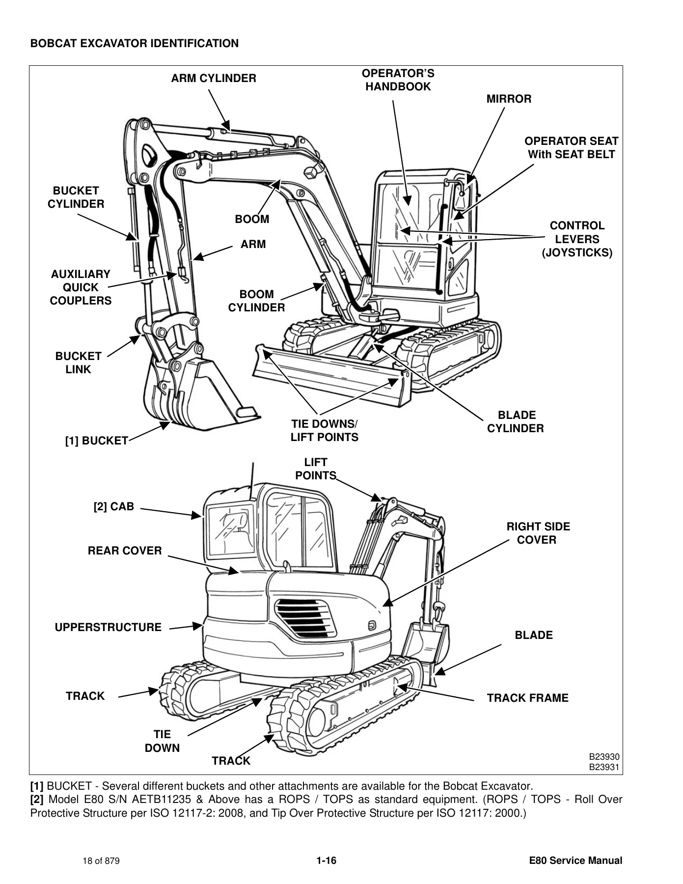
Serial plates are documented with photos. The excavator plate sits on the swing frame at the front of the upperstructure. The number is explained as a four-digit model / engine combination module plus a five-digit production sequence. The engine serial number is on the top cover. Delivery-report completion and machine identification drawings name boom, arm, bucket and blade cylinders, auxiliary quick couplers, cab, covers, tracks, lift points and tie-downs so parts conversations stay tied to the correct E80.

Chapters Covered

  • Safety & Maintenance — lifting and blocking; lifting the excavator; operator cab (door, front window, wiper, washer reservoir, right side window, HVAC ducts); trailer transport; right side, rear and center covers; service schedule; air cleaner; cab filter; engine cooling system; fuel system including biodiesel blend notes; engine lubrication; hydraulic fluid and filters; swing motor gearbox fluid; lubrication points; pivot pins; travel motor oil; spark arrester muffler; emergency exit; seat belt; cab tilt; control console lockouts; towing
  • Hydraulic System — circuit glossary and troubleshooting; boom, arm, boom swing, bucket, blade and optional articulated-boom cylinders; relief, port relief and pilot pressure-reducing valves; hydraulic control valve sections; piston pump with torque limiter and pump control; gear pump; manifold / accumulator; travel motor and gear-reduction hub; swivel joint; swing motor and drive carrier; control pattern selector; left and right joysticks; blade control valve; reservoir; oil cooler; direct-to-tank, auxiliary breaker, boom swing, auxiliary hydraulic, articulated boom, travel control and auto idle valves
  • Undercarriage — blade; rubber-track components (lug height, tension, removal, idler, tensioner, rollers, sprocket); steel-track components; track maintenance; swing circle gear; lower and upper track rollers
  • Upperstructure & Swing Section — upperstructure removal and installation; left and right side covers; cab; floor mat and related interior items; horn; swing frame; boom, arm, bucket and related structural work as presented in the section
  • Electrical System & Analysis — troubleshooting chart, fuses and relays; battery and jump starting; alternator belt, voltage and regulator tests; starter; boom lights; console lockout switch; fuel level sender; diagnostic service codes and engine check-lamp flash patterns; diagnostic tool software and code retrieval; instrument panel; key switch; right console switches including speed control and emergency stop; wiper motor; motion alarm; fuel transfer pump; auto idle pressure switch; full wiring schematic
  • Engine Service — engine information, specifications, troubleshooting, removal and compression test; speed-control adjustment; muffler; air cleaner housing; radiator, fan, fuel cooler, water pump and thermostat; lubrication system and oil-pressure test; fuel injection pump timing and injector testing; cylinder head and valve service; crankshaft and pistons; camshaft and timing gears; cold start device; EGR valve; manifold air heater; flywheel and hydraulic pump coupler
  • Heating, Ventilation and Air Conditioning (HVAC) — system description, troubleshooting, charging and reclamation, compressor, evaporator / heater unit, thermostat, HVAC controller and related components
  • Specifications — machine dimensions for standard, long-arm and articulated-boom layouts; performance, controls, engine, hydraulics, cylinders, cycle times, electrical, drive, slew, undercarriage, capacities, tracks and ground pressure; SAE and metric bolt torque; hydraulic connection specs; hydraulic fluid specs; conversion charts
  • Alphabetical Index

Taken together, those divisions give a technician a complete shop path on one compact excavator rather than a parts catalog or an operator handbook. Hydraulic work runs from leak-down cylinder tests through 12-spool closed-centre valve section rebuilds and piston-pump margin, backup-relief and torque-limiter settings. Undercarriage work covers both 450 mm rubber and steel tracks with five rollers per side. Electrical diagnosis includes service codes, E-ECU lamp patterns and a machine wiring schematic dated February 2011. Engine work goes past filters into injection timing, valve and bottom-end service on the Yanmar 4TNV98-ESDB8. HVAC pages cover R134a pressures and system charging. The specification chapter then locks dimensions, pressures, flows and fill quantities used throughout the procedures.

Safety, Daily Service and Shop Access

Opening chapters of the Bobcat E80 Compact Excavator Service Manual 6987194 (2011) S/N AETB11001 & AET311001 keep lift, block and fire-prevention rules next to the service schedule. Jackstands go under the blade and rear corners of the undercarriage before anyone works beneath the machine. One side can be raised about 101.6 mm (4 in) with boom and arm before stands take the weight. Whole-machine lifting uses fully extended bucket, arm and boom cylinders, a raised blade, chains at the blade ends and boom, protection against cab contact, and a maximum 45° angle between front and rear chains, with no operator on board and no swing during the lift.

Complete PDF Bookmark Tree

Complete Bookmarks

The complete bookmarks in the “Bobcat E80 Compact Excavator Service Manual 6987194 (2011) S/N AETB11001 & AET311001” are as follows:

MAINTENANCE SAFETYp. 3
CONTENTSp. 5
FOREWORDp. 7
FOREWORDp. 9
SAFETY INSTRUCTIONSp. 12
FIRE PREVENTIONp. 14
Maintenancep. 14
Operationp. 14
Electricalp. 14
Hydraulic Systemp. 14
Fuelingp. 14
Startingp. 14
Spark Arrestor Exhaust Systemp. 14
Welding And Grindingp. 15
Fire Extinguishersp. 15
SERIAL NUMBER LOCATIONSp. 16
Excavator Serial Numberp. 16
Engine Serial Numberp. 16
DELIVERY REPORTp. 17
BOBCAT EXCAVATOR IDENTIFICATIONp. 18
SAFETY & MAINTENANCEp. 19
LIFTING AND BLOCKING THE EXCAVATORp. 21
Procedurep. 21
LIFTING THE EXCAVATORp. 23
Procedurep. 23
OPERATOR CABp. 25
Descriptionp. 25
Cab Doorp. 25
Front Windowp. 26
Front Wiperp. 27
Window Washer Reservoirp. 27
Right Side Windowp. 28
Heating, Ventilation And Air Conditioning Ductp. 29
TRANSPORTING THE EXCAVATOR ON A TRAILERp. 31
Loading And Unloadingp. 31
Fasteningp. 31
RIGHT SIDE COVERp. 33
Opening And Closingp. 33
Adjusting The Latchp. 33
REAR COVERp. 35
Opening And Closingp. 35
CENTER COVERp. 37
Opening And Closingp. 37
SERVICE SCHEDULEp. 39
Chartp. 39
AIR CLEANER SERVICEp. 41
Daily Checkp. 41
Replacing The Filtersp. 41
CAB FILTERp. 43
Cleaning And Maintenancep. 43
ENGINE COOLING SYSTEMp. 45
Cleaningp. 45
Checking Levelp. 45
Removing And Replacing Coolantp. 46
FUEL SYSTEMp. 47
Fuel Specificationsp. 47
Biodiesel Blend Fuelp. 47
Filling The Fuel Tankp. 48
Fuel Filtersp. 49
Draining The Fuel Tankp. 50
Removing Air From The Fuel Systemp. 50
ENGINE LUBRICATION SYSTEMp. 51
Checking And Adding Engine Oilp. 51
Engine Oil Chartp. 51
Removing And Replacing Oil And Filterp. 52
HYDRAULIC SYSTEMp. 53
Checking And Adding Fluidp. 53
Hydraulic Fluid Chartp. 54
Removing And Replacing Hydraulic Filtersp. 54
Removing And Replacing Hydraulic Fluidp. 58
Checking Swing Motor Gear Box Fluid Levelp. 59
Removing And Replacing Swing Motor Gear Box Fluidp. 60
LUBRICATING THE EXCAVATORp. 61
Lubrication Locationsp. 61
PIVOT PINSp. 65
Inspection And Maintenancep. 65
TRAVEL MOTORp. 67
Checking And Adding Oilp. 67
Removing And Replacing Oilp. 67
SPARK ARRESTER MUFFLERp. 69
Cleaning Procedurep. 69
EMERGENCY EXITp. 71
Right Rear Side Windowp. 71
Front Windowp. 71
SEAT BELTp. 73
Inspection And Maintenancep. 73
CAB TILT PROCEDUREp. 75
Tilting The Cabp. 75
CONTROL CONSOLE LOCKOUTSp. 77
Inspection And Maintenancep. 77
TOWING THE EXCAVATORp. 79
Procedurep. 79
HYDRAULIC SYSTEMp. 81
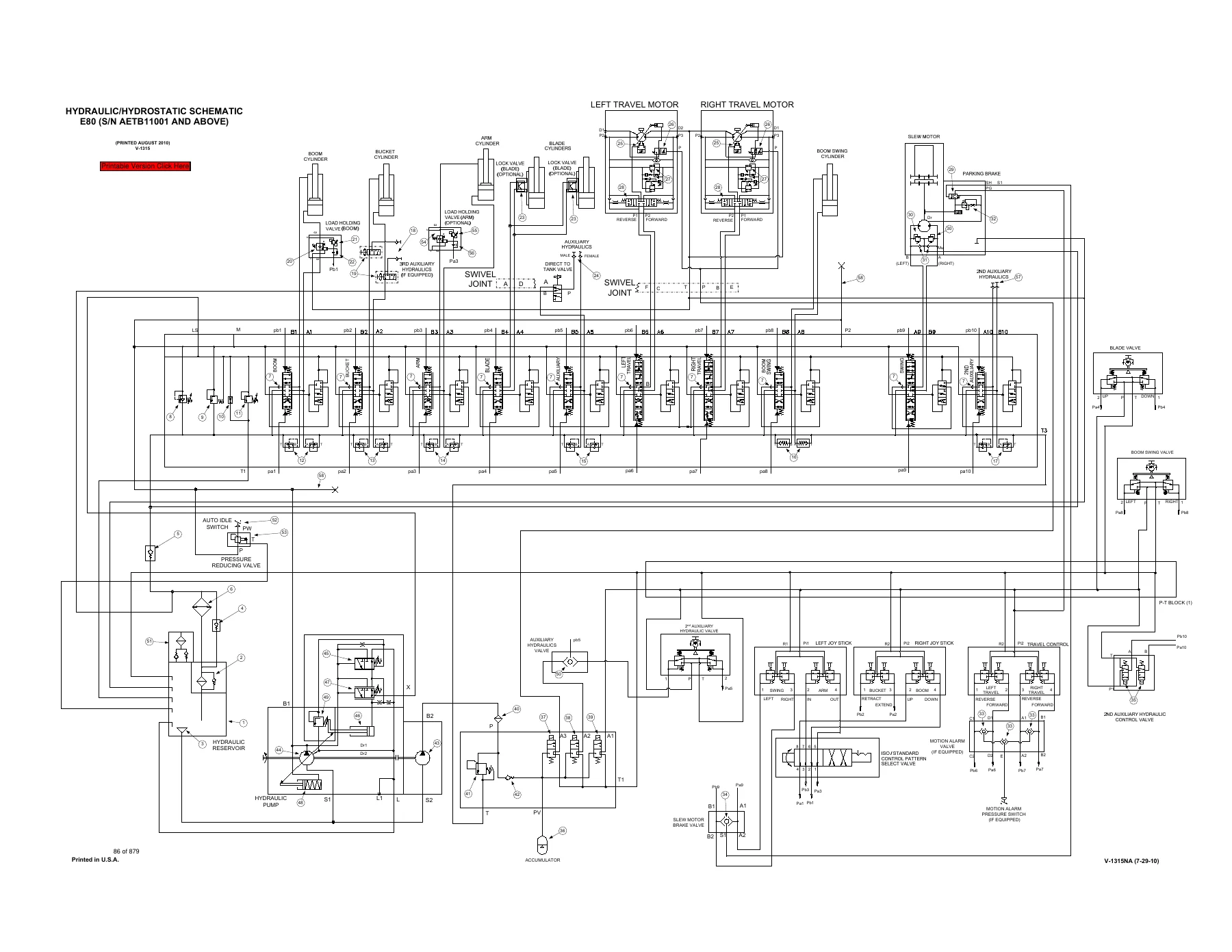
HYDRAULIC / HYDROSTATIC SCHEMATICSp. 85
HYDRAULIC SYSTEM INFORMATIONp. 89
Glossary Of Hydraulic / Hydrostatic Symbolsp. 89
Troubleshooting The Hydraulic Circuitp. 92
Troubleshooting The Cylinder Circuitp. 93
Troubleshooting The Swing (Slew) Circuitp. 94
Troubleshooting The Travel Circuitp. 95
Descriptionp. 97
CYLINDER (BOOM)p. 99
Testingp. 99
Removal And Installationp. 102
Parts Identificationp. 105
Disassemblyp. 106
Assemblyp. 114
CYLINDER (ARM)p. 123
Testingp. 123
Removal And Installationp. 125
Parts Identificationp. 128
Disassemblyp. 129
Assemblyp. 137
CYLINDER (BOOM SWING)p. 145
Testingp. 145
Removal And Installationp. 146
Parts Identificationp. 149
Disassemblyp. 150
Assemblyp. 157
CYLINDER (BUCKET)p. 165
Testingp. 165
Removal And Installationp. 165
Parts Identificationp. 168
Disassemblyp. 169
Assemblyp. 178
CYLINDER (BLADE)p. 187
Testingp. 187
Removal And Installationp. 188
Parts Identificationp. 191
Disassemblyp. 192
Assemblyp. 200
CYLINDER (ARTICULATED BOOM) (OPTIONAL)p. 209
Testingp. 209
Removal And Installationp. 211
Parts Identificationp. 213
Disassemblyp. 214
Assemblyp. 220
VALVES (RELIEF)p. 227
Descriptionp. 227
VALVES (PORT RELIEF)p. 229
Testing And Adjusting The Port Relief Valve Pressurep. 229
VALVE (PILOT PRESSURE RELIEF)p. 231
Testing And Adjusting The Pressure Reducing Valvep. 231
HYDRAULIC CONTROL VALVEp. 233
Descriptionp. 233
Removal And Installationp. 233
Parts Identificationp. 235
Disassembly And Assemblyp. 236
Inlet Valve Section Disassembly And Assemblyp. 241
Boom, Arm And Bucket Valve Section Disassembly And Assemblyp. 244
Left Travel, Right Travel And Blade Valve Section Disassembly And Assemblyp. 248
Auxiliary And Slew Valve Section Disassembly And Assemblyp. 252
Boom Swing Valve Section Disassembly And Assemblyp. 256
Articulated Boom Valve Section Disassembly And Assemblyp. 259
PUMP (HYDRAULIC PISTON)p. 263
Hydraulic Pump Work Sheetp. 263
Testing Informationp. 266
Pump Testingp. 268
Removal And Installationp. 276
Torque Limiter Valve Parts Identificationp. 278
Torque Limiter Valve Removal And Installationp. 279
Torque Limiter Valve Disassemblyp. 280
Torque Limiter Valve Assemblyp. 284
Initial Torque Limiter Valve Settingp. 288
Pump Control Parts Identificationp. 290
Pump Control Removal And Installationp. 291
Pump Control Disassembly And Assemblyp. 292
Parts Identificationp. 297
Disassemblyp. 298
Assemblyp. 306
PUMP (GEAR)p. 315
Testing Informationp. 315
Pump Testingp. 315
Removal And Installationp. 317
Disassembly And Assemblyp. 319
MANIFOLD ASSEMBLY / ACCUMULATORp. 323
Descriptionp. 323
Removal And Installationp. 323
Disassembly And Assemblyp. 324
TRAVEL MOTORp. 327
Removal And Installationp. 327
Parts Identificationp. 328
Parts Identification Gear Reduction Hubp. 329
Disassemblyp. 330
Assemblyp. 344
SWIVEL JOINTp. 359
Removal And Installationp. 359
Parts Identificationp. 362
Disassemblyp. 363
Assemblyp. 364
SWING MOTORp. 367
Removal And Installationp. 367
Parts Identificationp. 369
Disassembly And Assemblyp. 370
SWING MOTOR (DRIVE CARRIER)p. 379
Removal And Installationp. 379
Parts Identificationp. 380
Disassembly And Assemblyp. 381
CONTROL PATTERN SELECTOR VALVEp. 385
Removal And Installationp. 385
Parts Identificationp. 386
Disassemblyp. 387
Assemblyp. 389
RIGHT CONTROL LEVER (JOYSTICK)p. 391
Testingp. 391
Handle Removal And Installationp. 392
Joystick Assembly Removal And Installationp. 393
Parts Identificationp. 395
Disassembly And Assemblyp. 396
LEFT CONTROL LEVER (JOYSTICK)p. 401
Testingp. 401
Handle Removal And Installationp. 402
Joystick Assembly Removal And Installationp. 403
Parts Identificationp. 405
Disassembly And Assemblyp. 406
BLADE CONTROL VALVEp. 411
Removal And Installationp. 411
Parts Identificationp. 412
Disassembly And Assemblyp. 413
HYDRAULIC RESERVOIRp. 417
Removal And Installationp. 417
OIL COOLERp. 423
Removal And Installationp. 423
DIRECT TO TANK VALVEp. 425
Removal And Installationp. 425
Disassembly And Assemblyp. 426
AUXILIARY BREAKER VALVEp. 427
Descriptionp. 427
Removal And Installationp. 427
Parts Identificationp. 428
Disassembly And Assemblyp. 429
BOOM SWING VALVEp. 431
Removal And Installationp. 431
Parts Identificationp. 432
Disassembly And Assemblyp. 433
AUXILIARY HYDRAULIC VALVEp. 437
Removal And Installationp. 437
Parts Identificationp. 438
Disassembly And Assemblyp. 439
ARTICULATED BOOM VALVE (OPTIONAL)p. 443
Removal And Installationp. 443
Parts Identificationp. 444
Disassembly And Assemblyp. 445
TRAVEL CONTROL VALVEp. 449
Removal And Installationp. 449
Parts Identificationp. 451
Disassembly And Assemblyp. 452
AUTO IDLE VALVEp. 457
Testing And Adjustingp. 457
Removal And Installationp. 458
UNDERCARRIAGEp. 461
BLADEp. 463
Removal And Installationp. 463
TRACK UNDERCARRIAGE COMPONENTS (RUBBER TRACK)p. 465
Track Lug Heightp. 465
Checking Tensionp. 466
Adjusting Tensionp. 467
Track Removal And Installationp. 468
Idler Removal And Installationp. 470
Idler Parts Identificationp. 471
Idler Disassemblyp. 472
Idler Assemblyp. 475
Track Tensioner Removal And Installationp. 480
Track Tensioner Parts Identificationp. 481
Track Tensioner Disassembly And Assemblyp. 482
Roller Removal And Installationp. 484
Lower Roller Parts Identificationp. 486
Lower Roller Disassemblyp. 487
Lower Roller Assemblyp. 490
Upper Roller Parts Identificationp. 496
Upper Roller Disassembly And Assemblyp. 497
Sprocket Removal And Installationp. 500
TRACK MAINTENANCEp. 501
Track Damage Identificationp. 501
SWING CIRCLE GEARp. 513
Swing Bearing Removalp. 513
Swing Bearing Installationp. 514
LOWER TRACK ROLLERp. 515
Parts Identificationp. 515
Disassemblyp. 516
Assemblyp. 519
UPPER TRACK ROLLERp. 525
Parts Identificationp. 525
Disassembly And Assemblyp. 526
SWING CIRCLE GEARp. 529
Swing Bearing Removalp. 529
Swing Bearing Installationp. 530
UPPERSTRUCTURE & SWING SECTIONp. 531
UPPERSTRUCTUREp. 535
Removalp. 535
Installationp. 537
UPPERSTRUCTURE SIDE COVER (LEFT)p. 539
Removal And Installationp. 539
UPPERSTRUCTURE SIDE COVER (RIGHT)p. 541
Removal And Installationp. 541
CABp. 543
Removal And Installationp. 543
Door Removal And Installationp. 557
Front Window Removal And Installationp. 558
Lower Front Window Removal And Installationp. 559
Glass Installationp. 560
Front Window Strut Removal And Installationp. 565
Front Window Slide Bar Removal And Installationp. 566
Cab Tilt Assembly Removal And Installationp. 567
Cab Tilt Parts Identificationp. 568
Cab Tilt Assembly Disassembly And Assemblyp. 569
Headliner Removal And Installationp. 570
SEATp. 575
Seat Removal And Installationp. 575
Seat Mount Removal And Installationp. 576
RIGHT CONSOLEp. 579
Console Cover Removal And Installationp. 579
LEFT CONSOLEp. 581
Lower Console Cover Removal And Installationp. 581
Upper Console Cover Removal And Installationp. 582
Gas Strut Removal And Installationp. 583
Lock Lever Removal And Installationp. 584
Lock Lever Disassembly And Assemblyp. 585
Console Removal And Installationp. 586
CENTER COVERp. 587
Removal And Installationp. 587
CENTER ACCESS COVERp. 589
Removal And Installationp. 589
COUNTERWEIGHTp. 591
Removal And Installationp. 591
FLOOR MATp. 595
Removal And Installationp. 595
FUEL TANKp. 597
Removal And Installationp. 597
HORNp. 601
Removal And Installationp. 601
SWING FRAMEp. 603
Removal And Installationp. 603
Bushing Removalp. 607
Bushing Installationp. 608
BOOMp. 609
Removal And Installationp. 609
Bushing Removal And Installationp. 610
BOOM (ARTICULATED) (OPTIONAL)p. 611
Removal And Installationp. 611
ARMp. 613
Removal And Installationp. 613
Arm To Boom Bushing Removal And Installationp. 614
Bucket And Link Bushing Removal And Installationp. 615
QUICK COUPLER (KLAC SYSTEM™)p. 617
Troubleshootingp. 617
Daily Inspectionp. 617
Removal And Installationp. 618
Parts Identificationp. 620
Disassemblyp. 621
Assemblyp. 623
QUICK COUPLER (LEHNHOFF SYSTEM®)p. 625
Troubleshootingp. 625
Daily Inspectionp. 625
Removal (MS03 And MS08)p. 626
Installation (MS03 And MS08)p. 627
Parts Identification (MS03)p. 628
Disassembly And Assembly (MS03)p. 629
Parts Identification (MS08)p. 630
Disassembly (MS08)p. 631
Assembly (MS08)p. 635
BUCKETp. 639
Bucket Teeth Removal And Installationp. 639
Bucket Side Cutting Edge Removal And Installationp. 640
RIGHT SIDE COVERp. 641
Removal And Installationp. 641
Latch Adjustmentp. 643
REAR COVERp. 645
Removal And Installationp. 645
ELECTRICAL SYSTEM & ANALYSISp. 647
ELECTRICAL SCHEMATICSp. 649
ELECTRICAL SYSTEM INFORMATIONp. 650
Troubleshooting Chartp. 650
Descriptionp. 651
Fuse And Relay Location / Identificationp. 651
BATTERYp. 654
Servicingp. 654
Removal And Installationp. 655
Using A Booster Battery (Jump Starting)p. 656
ALTERNATORp. 658
Belt Adjustmentp. 658
Belt Replacementp. 658
Charging System Inspectionp. 659
Alternator Voltage Testingp. 661
Low Voltage Testingp. 662
High Voltage Testingp. 662
Alternator Regulator Testingp. 663
Removal And Installationp. 664
Parts Identificationp. 666
STARTERp. 668
Testingp. 668
Removal And Installationp. 669
Parts Identificationp. 671
LIGHTSp. 672
Boom Light Removal And Installationp. 672
Boom Light Bulb Replacementp. 672
CONSOLE LOCKOUT SWITCHp. 674
Testing / Adjustmentp. 674
Removal And Installationp. 675
FUEL LEVEL SENDERp. 676
Removal And Installationp. 676
DIAGNOSTIC SERVICE CODEp. 678
Service Codes Listp. 678
Flashing Patterns Of Engine Check Lampp. 681
DIAGNOSTIC TOOLp. 682
Software Installationp. 682
Installationp. 684
Code Retrievalp. 687
INSTRUMENT PANELp. 692
Removal And Installationp. 692
Disassembly And Assemblyp. 693
KEY SWITCHp. 696
Removal And Installationp. 696
RIGHT CONSOLE SWITCH COVERp. 698
Removal And Installationp. 698
Rocker Switch Removal And Installationp. 699
Speed Control Removal And Installationp. 700
Engine Emergency Stop Switch Removal And Installationp. 700
Auxiliary Power Outlet Removal And Installationp. 701
WIPER MOTORp. 702
Removal And Installationp. 702
MOTION ALARM SYSTEM (IF EQUIPPED)p. 704
Descriptionp. 704
Inspectingp. 704
Adjusting Switch Positionp. 705
FUEL TRANSFER PUMPp. 706
Removal And Installationp. 706
AUTO IDLE PRESSURE SWITCHp. 708
Removal And Installationp. 708
ENGINE SERVICEp. 710
ENGINE INFORMATIONp. 712
Descriptionp. 712
Specificationsp. 713
Troubleshootingp. 719
Engine Removal And Installationp. 720
Compression – Testingp. 727
ENGINE SPEED CONTROLp. 730
Adjustmentp. 730
MUFFLERp. 732
Removal And Installationp. 732
AIR CLEANERp. 734
Housing Removal And Installationp. 734
ENGINE COOLING SYSTEMp. 736
Radiator Removal And Installationp. 736
Radiator Disassembly And Assemblyp. 743
Fan Removal And Installationp. 745
Fuel Cooler Removal And Installationp. 746
Water Pump Removal And Installationp. 747
Water Pump Parts Identificationp. 748
Thermostat Removal And Installationp. 749
Temperature Switch – Testingp. 749
Temperature Sensor – Testingp. 750
Thermostat – Testingp. 750
LUBRICATION SYSTEMp. 752
Oil Pan Removal And Installationp. 752
Oil Pump Removal And Installationp. 753
Oil Pump Inspectionp. 755
Engine Oil Pressure – Testingp. 757
FUEL SYSTEMp. 758
Fuel Injection Pump Removal And Installationp. 758
Fuel Injection Pump – Timingp. 763
Fuel Injector Removal And Installationp. 767
Fuel Injector Pressure – Testingp. 769
Nozzle Spray Conditionp. 769
CYLINDER HEADp. 772
Valve Clearance Adjustmentp. 772
Cylinder Head Removal And Installationp. 774
Cylinder Head Disassembly And Assemblyp. 775
Cylinder Head – Servicingp. 776
Valve Guide – Inspectionp. 777
Intake And Exhaust Valve – Inspectionp. 778
Valve Stem Bend – Inspectionp. 778
Valve Face And Seatp. 779
Valve Spring – Inspectionp. 779
Push Rod – Inspectionp. 780
Rocker Arm – Inspectionp. 780
Valve Bridge – Inspectionp. 781
CRANKSHAFT AND PISTONSp. 782
Piston And Connecting Rod Removal And Installationp. 782
Piston And Connecting Rod – Servicingp. 783
Cylinder Bore – Inspectionp. 785
Crankshaft End Playp. 785
Crankshaft And Bearings Removal And Installationp. 786
Crankshaft And Bearings – Servicingp. 787
CAMSHAFT AND TIMING GEARSp. 788
Timing Gear Case Cover Removal And Installationp. 788
Timing Gear Backlash – Inspectionp. 789
Idler Gear And Camshaft Removal And Installationp. 790
Camshaft – Servicingp. 791
Idler Gear And Shaft – Servicingp. 792
COLD START DEVICEp. 794
Descriptionp. 794
Testingp. 794
Removal And Installationp. 794
EXHAUST GAS RECIRCULATION VALVE (EGR)p. 796
Descriptionp. 796
Testingp. 796
Removal And Installationp. 797
MANIFOLD AIR HEATERp. 798
Descriptionp. 798
Testingp. 798
Removal And Installationp. 798
ENGINE FLYWHEELp. 800
Hydraulic Pump Coupler Removal And Installationp. 800
Flywheel Removal And Installationp. 801
Flywheel Ring Gear Removal And Installationp. 801
HEATING, VENTILATION AND AIR CONDITIONING (HVAC)p. 802
AIR CONDITIONING SYSTEM FLOWp. 804
Descriptionp. 804
Chartp. 805
Componentsp. 806
Safety Equipmentp. 809
REGULAR MAINTENANCEp. 810
Filtersp. 810
Belt Adjustmentp. 810
Belt Replacementp. 811
Condenserp. 812
Air Conditioning Service Chartp. 813
Evaporator / Heater Coilp. 814
TROUBLESHOOTINGp. 816
Blower Motor Does Not Operatep. 816
Blower Motor Operates Normally, But Air Flow Is Insufficientp. 816
Insufficient Cooling Although Air Flow And Compressor Operation Are Normalp. 816
The Compressor Operates Improperly Or Not At Allp. 816
Gauge Pressure Related Troubleshootingp. 817
Temperature / Pressure Chartp. 819
Poor A/C Performancep. 820
HVAC Repair And Leaksp. 821
SYSTEM CHARGING AND RECLAMATIONp. 822
Reclamation And Charging With Recovery / Charging Unitp. 822
Charging With A Manifold Gauge Setp. 825
COMPRESSORp. 828
Removal And Installationp. 828
Oilp. 830
Oil Checkp. 831
CONDENSERp. 834
Removal And Installationp. 834
RECEIVER / DRIERp. 836
Receiver / Drier Removal And Installationp. 836
Pressure Switch Removal And Installationp. 837
EVAPORATOR / HEATER UNITp. 838
Removal And Installationp. 838
THERMOSTATp. 840
Inspectionp. 840
EXPANSION VALVEp. 842
Removal And Installationp. 842
BLOWER FANp. 844
Removal And Installationp. 844
HEATER VALVEp. 846
Removal And Installationp. 846
HVAC CONTROLLERp. 848
Removal And Installationp. 848
SPECIFICATIONSp. 850
E80 EXCAVATOR SPECIFICATIONSp. 852
Machine Dimensionsp. 852
Machine Dimensions (Articulated Boom)p. 853
Machine Dimensions (Standard Arm)p. 855
Machine Dimensions (Long Arm)p. 856
Performancep. 857
Controlsp. 857
Enginep. 857
Hydraulic Systemp. 858
Hydraulic Cylindersp. 858
Hydraulic Cycle Timesp. 859
Electricalp. 859
Drive Systemp. 859
Slew Systemp. 859
Undercarriagep. 859
Capacitiesp. 859
Tracksp. 860
Ground Pressurep. 860
TORQUE SPECIFICATIONS FOR BOLTSp. 862
Torque For General SAE Boltsp. 862
Torque For General Metric Boltsp. 863
HYDRAULIC CONNECTION SPECIFICATIONSp. 864
O-ring Face Seal Connectionp. 864
Straight Thread O-ring Fittingp. 865
Tubelines And Hosesp. 865
Flare Fittingp. 865
Port Seal Fittingp. 866
HYDRAULIC FLUID SPECIFICATIONSp. 868
Specificationsp. 868
CONVERSIONSp. 870
Decimal And Millimeter Equivalent Chartp. 870
U.S. To Metric Conversion Chartp. 870
ALPHABETICAL INDEXp. 872
SERVICE MANUAL REVISIONp. 874
Revision No: E80 – 1p. 874
Revision No: E80 – 2p. 876
Revision No: E80 – 3p. 878

Cab pages distinguish earlier cabs from S/N AETB11235 & Above and S/N AET311235 & Above, which list ROPS / TOPS to ISO 12117-2:2008 and ISO 12117:2000 and require the seat belt for that protection. Front-window latch pins, right-side window latch, seven adjustable air vents, washer reservoir location ahead of the radiator, and cab-tilt warnings (never work under the cab without an approved support) sit in the same section as trailer loading: metal ramps, angle not over 15°, auto idle off, two-speed travel in low range, blade forward, and chains at both blade corners plus the rear track-frame tie-down loop.

The service chart spaces coolant, engine oil, air filter, hydraulic fluid and filters, swing gearbox oil, travel-motor oil, grease fittings and spark-arrester muffler cleaning across 50 / 100 / 250 / 500 / 1000 / 2000 hour marks. Fuel pages specify clean Grade No. 2 or Grade No. 1 diesel with a cetane number of 45 or higher and limit biodiesel blends; more than five percent biodiesel is called out as a risk to hoses, injectors and seals. After a run-dry event the electric fuel pump is used with the key ON for 10–15 seconds to purge air. Hydraulic sight-glass checks are made with arm and bucket retracted, bucket and blade on the ground.

Hydraulics, Travel and Swing Work

Hydraulic system information states two separate circuits, with the piston-pump circuit feeding the control valve that contains boom, bucket, arm, blade, auxiliary, left and right travel, boom swing and upperstructure swing sections. Separate troubleshooting tables cover the main circuit, cylinders, slew and travel. Each work cylinder chapter follows the same shop rhythm: relieve residual pressure with the engine off and key ON, test for internal leakage, remove and install, then identify, disassemble and assemble parts. Optional articulated-boom cylinders and valve sections are included for machines so equipped.

Pump work is measurement-heavy. Piston-pump testing is done with oil at 50–60°C (122–140°F) after high idle is confirmed. Recorded targets in the test sequences include pilot / pressure-reducing values around 3200 kPa (32 bar) (464 psi), pump-margin and load-sense settings, backup relief near 34000 kPa (340 bar) (4931 psi), load-sense relief near 28000 kPa (280 bar) (4060 psi), and free flow of 144 L/min (38 U.S. gpm) used while setting the torque limiter. Gear-pump free flow on a new pump is given as 21.9 L/min (5.8 U.S. gpm) at 2200 engine rpm. Dual hydraulic / hydrostatic schematics printed August 2010 serve S/N AETB11001 and above (V-1315) and S/N AET311001 and above (V-1315EMEA), including optional third-auxiliary, breaker, motion-alarm and articulated-boom circuits.

Travel motors are independently driven axial-piston units with two-stage planetary reduction; the manual separates motor removal from gear-reduction-hub parts identification, disassembly and assembly. Swing work covers the axial-piston slew motor, drive carrier and the single-row shear-type ball bearing with internal gear. Joystick testing, control-pattern selector service, accumulator description (short-term reserve pressure with engine off and key in run), and auto-idle valve test and adjustment close the hydraulic book for day-to-day control complaints.

Undercarriage, Electrical Diagnosis and Engine Rebuild

Rubber-track service measures lug height, sets grease-cylinder tension, and walks idler, tensioner, roller and sprocket R&I with floating-seal assembly using alcohol on the O-ring and a light oil film only on the metal seal faces. Steel-track pages add shoe-count and tension checks for the 39-shoe, 450 mm (17.7 in) chain. Track-maintenance text explains rubber-track damage modes so a worn or cut belt is not treated as a simple tension problem. Swing-circle bearing removal is tied to full upperstructure lift-off, with alignment pins and match marks required on reassembly.

Electrical system analysis starts with a cause-and-correction chart for no-charge and no-crank complaints, then fuse and relay maps. Battery jump-starting routes the ground to a flywheel-cover bolt. Alternator pages cover belt tension, regulator checks and a 12 V, 60 A open-frame unit with internal regulator. Starter testing precedes gear-reduction starter R&I. Diagnostic service codes list sensor, rack-actuator, overspeed and oil-pressure failures with the resulting engine behavior and the flash pattern of the engine check lamp. A diagnostic-tool chapter covers software install, PC connection and code retrieval. The wiring schematic on the analysis section is titled for both S/N AETB11001 and S/N AET311001 ranges and dated February 2011 (V-1316).

Engine service identifies a Yanmar direct-injected 4TNV98-ESDB8 four-cylinder diesel, 3.319 L (202.5 in³), 98 x 110 mm (3.85 x 4.33 in) bore and stroke, counter-clockwise rotation from the flywheel, closed crankcase ventilation and dual dry air cartridges. The specification chapter lists SAE Gross 40.7 kW (54.6 hp), torque 223–243 N·m (164.5–179.1 ft-lb) at 1300 rpm, low idle 1050 rpm and high idle 2150 rpm. Shop procedures include engine R&I, compression testing with kit MEL10630 (3330 kPa class values at 250 rpm cranking), injection-pump timing using the pump index and flywheel TDC / BTDC marks, injector spray and pressure tests, valve clearance, head and guide service, piston and crankshaft limits, camshaft and idler-gear backlash, cold-start device operation below 5°C (41°F), EGR coil tests, manifold air heater preheat and flywheel / pump-coupler work. Oil-pressure limits include 60 kPa (0.6 bar) (8.7 psi) or more at idle.

IMAGES PREVIEW

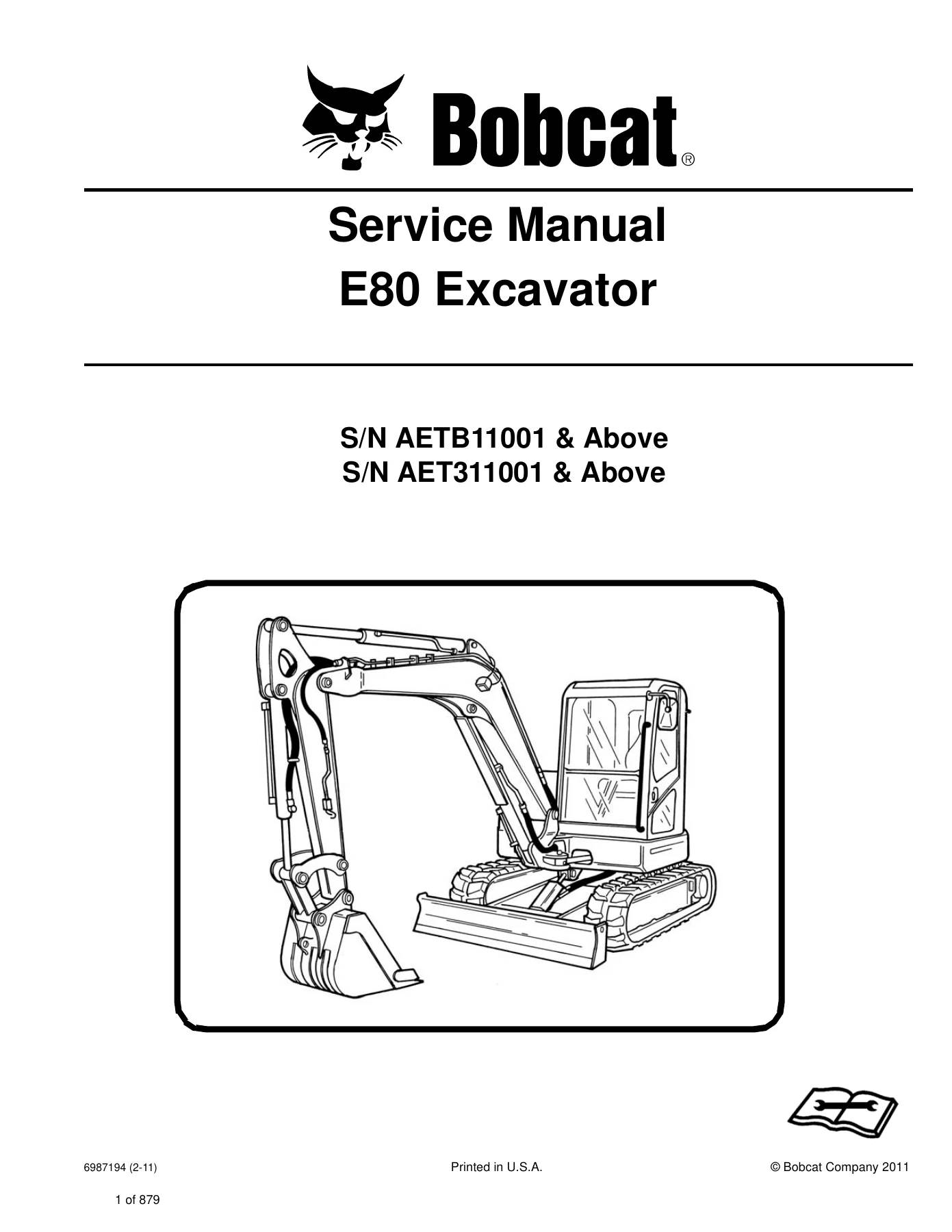
Bobcat E80 Compact Excavator Service Manual 6987194 (2011) S/N AETB11001 & AET311001 — PDF page 1 preview
Bobcat E80 Compact Excavator Service Manual 6987194 (2011) S/N AETB11001 & AET311001 — PDF page 18 preview
Bobcat E80 Compact Excavator Service Manual 6987194 (2011) S/N AETB11001 & AET311001 — PDF page 86 preview

Capacities, Pressures and Machine Figures Used in the Shop

Keep these published figures beside the work order when using this Bobcat E80 Compact Excavator Service Manual 6987194 (2011) S/N AETB11001 & AET311001. Operating weight with cab, steel tracks and a 610 mm (24 in) bucket is 8380 kg (18475 lb); add 60 kg (133 lb) for the long arm or 920 kg (2028 lb) for the articulated-boom option. Travel speed is 2.9 km/h (1.8 mph) low and 4.6 km/h (2.9 mph) high. Digging force per ISO 6015 is 40855 N (9185 lbf) on the standard or articulated-boom arm, 34068 N (7659 lbf) on the long arm, and 54623 N (12280 lbf) at the bucket. Boom offset is 70° left and 55° right. Slew speed is 9.6 rpm. Ground pressure is 39 kPa (0.39 bar) (5.66 psi).

Hydraulic hardware is an engine-driven variable-displacement dual piston pump with pressure-compensating, load-sensing and torque-limiter controls plus two gear pumps. Piston capacity is listed as 2 @ 70 L/min (18.5 U.S. gpm); gear pumps 70 L/min (18.5 U.S. gpm) and 9.9 L/min (2.6 U.S. gpm); auxiliary flow 120 L/min (31.7 U.S. gpm). System relief on travel, slew, boom swing, blade and primary work circuits is 30000 kPa (300 bar) (4278 psi). Port reliefs on arm, boom, bucket and optional articulated boom are 31000 kPa (310 bar) (4496 psi). Joystick control pressure is 2940 kPa (29.4 bar) (427 psi). Cylinder bore / rod / stroke tables cover boom 115 / 75 / 775 mm, arm 100 / 65 / 866 mm, bucket 85 / 55 / 690 mm, boom swing 110 / 60 / 738 mm, blade 100 / 60 / 149 mm and optional articulated boom 100 / 55 / 370 mm. Cycle times include boom raise 3.2 s / lower 3.0 s, arm retract 3.8 s / extend 2.9 s and bucket curl 3.3 s / dump 2.1 s.

Fill quantities: fuel tank 78 L (20.6 U.S. gal); hydraulic reservoir to sight-glass center 87 L (23.0 U.S. gal); hydraulic system with reservoir 127 L (35.5 U.S. gal); cooling system 10.0 L (10.6 qt); engine oil and filter 11.6 L (12.25 qt); each final drive 1.4 L (1.5 qt). Electrical specification is a 12 V, 750 CCA battery at -18°C (0°F), 60 A alternator and 3.0 kW (4.0 hp) gear-reduction starter, with air-intake heater as the starting aid. Dimension plates give overall layouts for standard arm, long arm and articulated boom, including transport height and reach figures used when planning lifts or trailer loads.

Use This Manual on the Job, Then Keep a Copy on Any Device

With the Bobcat E80 Compact Excavator Service Manual 6987194 (2011) S/N AETB11001 & AET311001 a technician can block and lift the machine, change planned-interval fluids and filters, test and rebuild boom through blade cylinders, set piston-pump margin and torque limiter, overhaul travel and swing motors, replace rubber or steel tracks and rollers, lift the upperstructure off the swing bearing, trace no-charge or no-crank faults, read E-ECU codes, time and test the 4TNV98-ESDB8 injection system, service head and bottom end, and charge the HVAC circuit to the pressures shown in the HVAC chapter. Matching those procedures to the printed relief settings, cylinder sizes, idle speeds and fill quantities is what keeps a compact excavator from coming back with the same leak, drift or derate. After purchase the file is delivered as an instant PDF with no shipping wait, opens on a shop computer, tablet or phone, and can be printed for the bench or service truck.
Reviews

There are no reviews yet.

Be the first to review “Bobcat E80 Compact Excavator Service Manual 6987194 (2011) S/N AETB11001 & AET311001”

What Our Customers Say

★★★★★ Live reviews from customers
Loading customer reviews...
0
    0
    Your Cart
    Your cart is emptyReturn to Shop
    🛒
    Recently Purchased
    🕒 verified order