
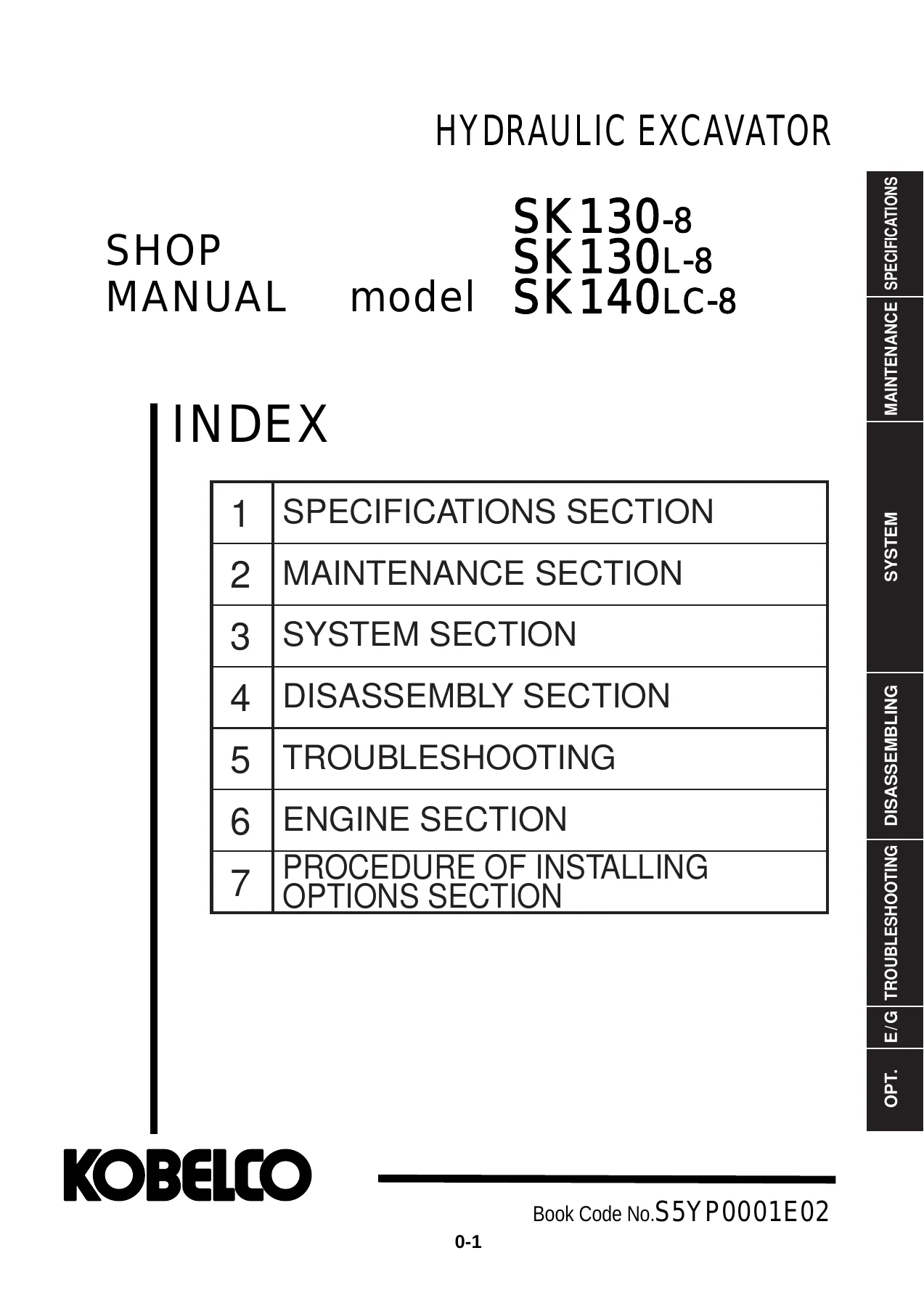
Kobelco SK130-8 SK130L-8 SK140LC-8 Shop Manual S5YP0001E02 Hydraulic Excavator Workshop PDF
Original price was: $39.95.$24.95Current price is: $24.95.
Shop manual for Kobelco SK130-8, SK130L-8 and SK140LC-8 hydraulic excavators (book code S5YP0001E02). Covers specifications, maintenance tests, mechatro/hydraulic/electrical systems, disassembly, error-code troubleshooting and the Mitsubishi D04FR engine.
Description
Kobelco SK130-8 SK130L-8 SK140LC-8 Shop Manual S5YP0001E02 Hydraulic Excavator Workshop PDF
This Kobelco SK130-8 SK130L-8 SK140LC-8 Shop Manual S5YP0001E02 Hydraulic Excavator Workshop PDF gathers the shop information used to inspect, adjust, diagnose and rebuild the SK130-8, SK130L-8 and SK140LC-8 hydraulic excavators. The compiled book is labeled Book Code No. S5YP0001E02 and is written for SE Asia, New Zealand and Thailand specification machines. Specifications material is dated July 2009 with a January 2010 revision that adds SK130-8 and SK130L-8 coverage alongside SK140LC-8.
File Details
- Manual type: Shop manual (hydraulic excavator)
- Brand / models: Kobelco SK130-8, SK130L-8, SK140LC-8
- Language: English
- Page count: 1122
- File format: PDF
- Book code: S5YP0001E02
- Specifications revision: January 2010 (first edition July 2009)
Machines, Serial Ranges and Powerplant
Applicable serial ranges printed in the specifications and electrical books are SK140LC-8 : YP09-05001~, SK130-8 : LP09-20001~ and SK130L-8 : LX07-11001~. Fully equipped weights in the component tables are 13,000 kg (28,600 lb) for SK140LC-8, 12,800 kg (28,220 lb) for SK130-8 and 14,700 kg (32,410 lb) for SK130L-8. Standard working equipment shown throughout the dimensional drawings is the 4.68 m (15 ft-4 in) boom with 2.38 m (7 ft-10 in) arm; bucket sizes listed with that combination include 0.50 m3 (0.65 cu-yd) on SK140LC-8 / SK130-8 and 0.45 m3 (0.59 cu-yd) on SK130L-8.
The engine chapter and specification sheets identify a MITSUBISHI D04FR-74kW water-cooled, 4-cycle, 4-cylinder direct-injection diesel with intercooler turbocharger. Bore and stroke are 102 mm x 130 mm (4.02 in x 5.12 in) and total displacement is 4.249 L (259.27 cu-in). Rated output is given as net 69.2 kW (94 PS) / 2,000 min-1 (ISO 9249) and net 74 kW (101 PS) / 2,000 min-1 (ISO 14396). Maximum torque is net 359 N-m (265 lbf-ft) / 1,600 min-1 (ISO 9249) and net 375 N-m (277 lbf-ft) / 1,600 min-1 (ISO 14396). The bound Mitsubishi service section titles the same family as D04FR-TAA. Starter rating is 24 V / 5.0 kW and the alternator is 24 V / 50 A.
Performance and Hydraulic Layout
Swing speed is 11 min-1. Travel speed is 3.4 / 5.6 km/h (2.1 / 3.5 mile/h) on SK140LC-8 and SK130-8, and 3.0 / 5.3 km/h (1.8 / 3.3 mile/h) on SK130L-8. Gradeability is 70% (35 degrees). Hydraulic hardware listed in the specifications section is a variable-displacement axial piston pump x 2 plus one gear pump, an axial-piston swing motor, two variable-displacement axial-piston travel motors with counterbalance valves, an 8-spool control valve, double-acting boom/arm/bucket cylinders and an air-cooled oil cooler. Standard schematic component models include hyd. pump K7V63DTP179R-0E13-VC, main control valve KMX13YD/B44904, swing motor M2X63CHB and travel motor GM21VX-A-45/75-2. Cylinder sizes printed with that schematic are boom 100 dia. x 70 dia. x 1092, arm 115 dia. x 80 dia. x 1120 and bucket 95 dia. x 65 dia. x 903.
IMAGES PREVIEW
Chapters Covered
- 1 Outline — general precautions for repairs; preparation before disassembling; safety when disassembling and assembling; hydraulic equipment; electrical equipment; hydraulic parts; weld repair; environmental issues; SI unit system
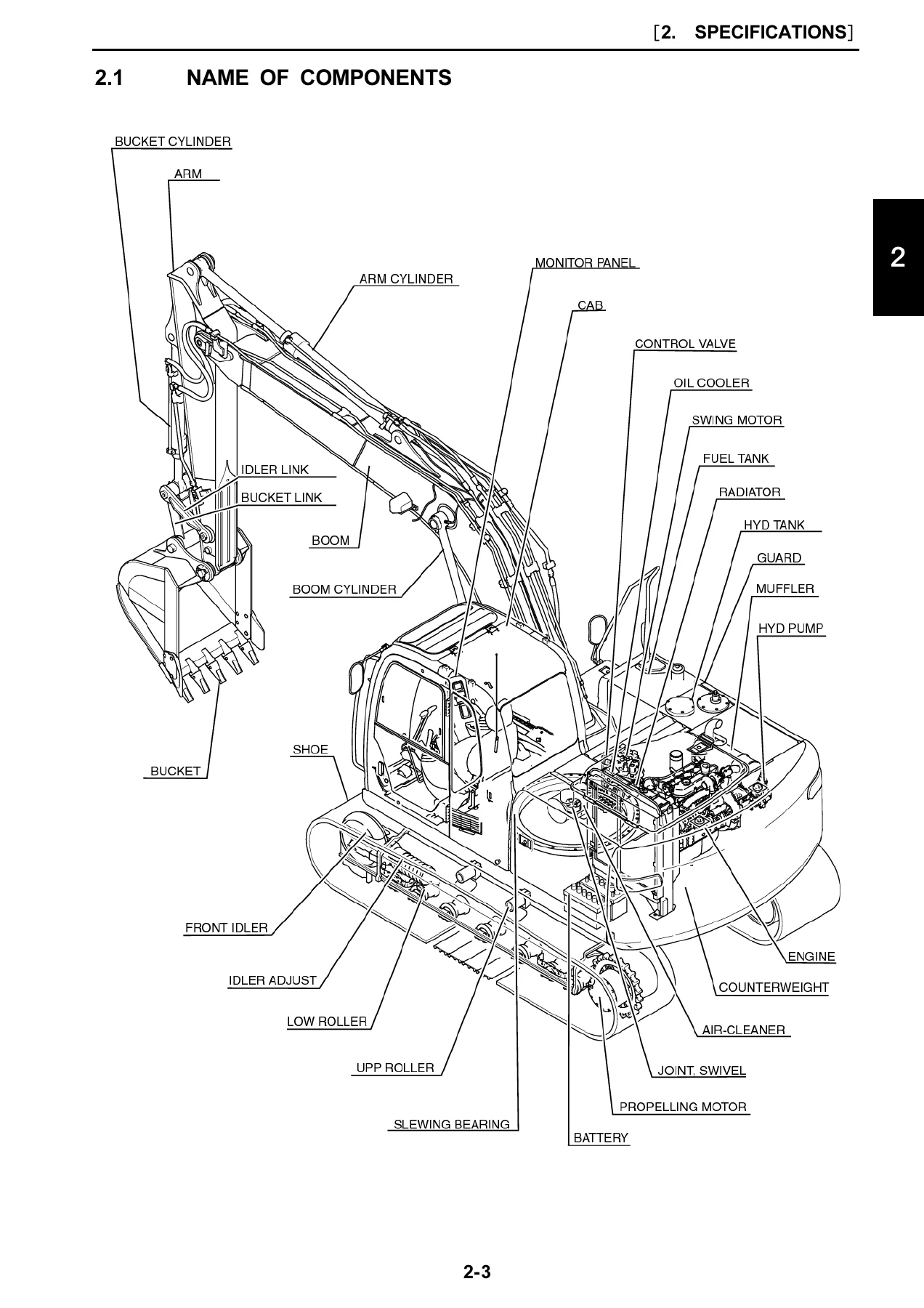
- 2 Specifications — name of components; general dimensions for SK140LC-8, SK130-8 and SK130L-8; weight of components; transportation dimensions; speed and climbing capability; engine and hydraulic component lists; crawler and bucket types; attachment combinations; engine specification and characteristic curve
- 3 Attachment Dimensions — boom, arm and bucket dimensional drawings and maintenance standards; lug and boss section drawings
- 11 Tools — tightening torques for capscrews, nuts, hoses and fittings; screw sizes; plugs; special tube spanners; special tools; locking/sealing compounds; suction stopper; counterweight, upper-frame and engine jigs; track spring set jig
- 12 Standard Maintenance Time Table — excavator working-time tables by group; engine maintenance service standard time list
- 13 Maintenance Standard and Test Procedure — performance inspection standard values; engine-speed measurement; hydraulic-pressure measurement and relief-valve adjustment; travel, swing and attachment performance tests; swing-bearing measurement; mechatro controller A-B-C adjustment
- 21 Mechatro Controller — unload, positive/P-Q, boom-up conflux, arm recirculation and anti-cavitation, swing priority, travel-straight and pressure-release control; multi display, self diagnosis, service diagnosis, trouble history, trouble diagnosis mode, maintenance-schedule setting
- 22 Hydraulic System — circuits and components; color coding; neutral, travel, bucket, boom, swing, arm and combined circuits; pressure draining
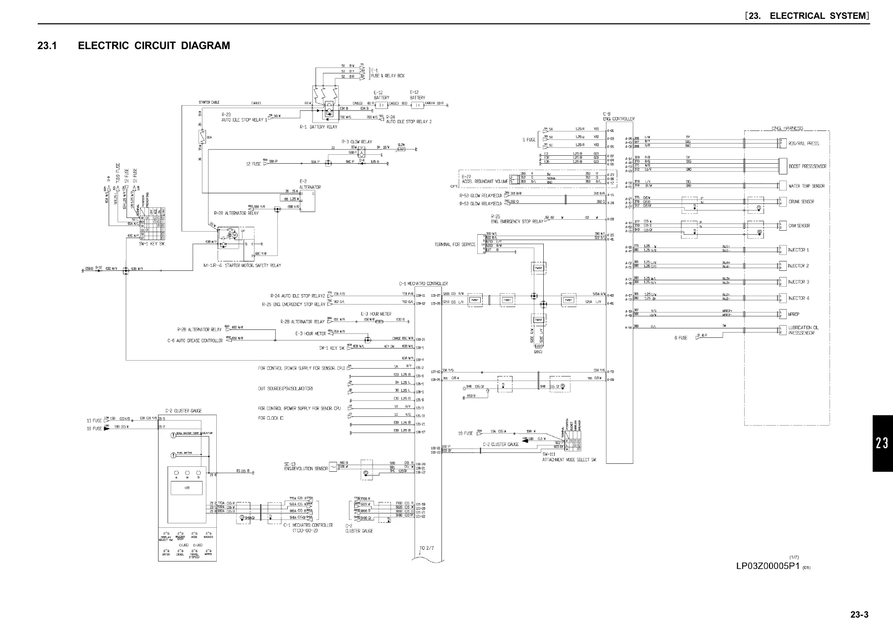
- 23 Electrical System — electric circuit diagram; equipment and harness lists; instrument panel, controller, operator switches, upper/engine/cab/boom harnesses and lighting
- 24 Components System — hydraulic pump-regulator, control valve, attachment and travel pilot valves, swing motor, travel motor (including L spec.), swivel joint, cylinders; electrical equipment list and specifications
- 25 Air-Conditioner System — HVAC air cycle and auto system; piping; cooling-circuit function; unit disassembly; refrigerant charging; electric circuit; troubleshooting and panel self diagnosis
- 31 Disassembling and Assembling — chapter format and tightening-torque indication
- 32 Attachments — removing and installing attachment assembly, bucket, arm and boom; cylinder disassembly
- 33 Upper Slewing Structure — seat, cab, battery, guards, tanks, pump, air cleaner, muffler, counterweight, radiator and oil cooler, engine, control valve, pilot valves, swing motor, swivel joint and upper frame; pump-regulator, control-valve, pilot-valve, swing-motor and swivel-joint overhaul
- 34 Travel System — crawler, upper and lower rollers, front idler/adjuster, sprocket, travel motor, swing bearing; travel-motor unit construction, tools, disassembly, assembly and maintenance standard
- 46 Troubleshooting by Error Codes — on-site judgment; failure classification; mechatro-controller blown fuse; code-by-code troubleshooting
- 47 Troubleshooting by Trouble — hydraulic-system faults; electrical wiring checks; engine-related troubleshooting tables
- 48 Troubleshooting — Trouble Diagnosis Mode
- 51 Engine — Mitsubishi D04FR-TAA / D04FR service data, basic-engine disassembly and inspection, fuel/lubrication/cooling systems, ECU Q-rank notes, adjustment, break-in and diagnosis-code troubleshooting
Taken together, the chapters give a technician the machine identity data, wear and performance limits, circuit theory, component overhaul sequences, error-code paths and the supplier engine overhaul book in one file. That is the practical scope of the Kobelco SK130-8 SK130L-8 SK140LC-8 Shop Manual S5YP0001E02 Hydraulic Excavator Workshop PDF rather than a short operator pamphlet.
Inspection Standards and Mechatro Work
Chapter 13 is the field-test core of this SK130-8 SK130L-8 SK140LC-8 shop manual. It shows how to warm the engine, read speed from the multi display or a diesel tachometer, install pressure gauges, locate relief-valve adjustment points and record travel speed, travel deviation, parking-brake hold, travel-motor drain, swing speed, swing-brake and swing-parking-brake performance, swing-motor drain, cylinder cycle time and cylinder oil tightness. Swing-bearing play measurement and mechatro A-B-C output adjustment sit in the same chapter so pump proportional-valve and unload-valve current can be aligned after a controller, engine, pump or unload-valve change.
Chapter 21 then explains why those currents matter. Unload-valve control, positive control and P-Q control, boom-up conflux, arm-in recirculation and anti-cavitation, arm-out conflux, bucket digging/dump, swing priority, travel-straight and pressure-release logic are described with the multi-display self-diagnosis, service-diagnosis screens, trouble-history and trouble-diagnosis mode. Default maintenance reminders printed with the display include engine oil, fuel filter, hydraulic oil filter and hydraulic oil hour intervals used by the schedule-set procedure.
Systems, Harness and Component Rebuild
Hydraulic System chapter 22 walks each circuit from neutral through travel, bucket, boom, swing, arm and combined operation, then the pressure-draining sequence used before cracking lines. Electrical System chapter 23 starts with the machine circuit diagram and continues through harness lists and install drawings for the instrument panel, mechatro controller, operator switches, upper structure, floor, engine, cab, washer tank, boom and lighting. Components System chapter 24 supplies construction and function for the pump-regulator, 8-spool valve, both pilot valves, swing motor, standard and L-spec travel motors, swivel joint and cylinders, plus the electrical-equipment list. Air-conditioner coverage includes refrigerant charging precautions, wiring and panel self-diagnosis indications.
Upper Structure, Travel Gear and Engine Overhaul
Disassembly chapters 32-34 are written as remove/install plus bench overhaul. Attachment work covers the complete front, bucket, arm, boom and cylinders. Upper slewing structure work runs from operator seat and cab through fuel and hydraulic tanks, pump, radiator/oil cooler, engine R&I, control valve, pilot valves, swing motor, swivel joint and upper frame, then the matching bench procedures. Travel-system work covers crawler separation, rollers, idler/adjuster, sprocket, travel motor and swing bearing, with a full travel-motor unit teardown, special tools/jigs, assembly order and wear standards. Tool chapter 11 backs those jobs with metric coarse-thread torque tables, hose/fitting torques, hydraulic plugs, tube spanners, suction stopper dimensions and lifting jigs for counterweight, upper frame, engine pedestal and track spring.
Engine section 51 is the Mitsubishi land-use service book bound into this workshop PDF. It covers D04FR-TAA specifications, service data and tightening torques, compression-pressure overhaul judgment, cylinder head and bottom-end disassembly/inspection/reassembly, fuel common-rail and injector service cautions, lubrication and cooling work, ECU replacement with Q-rank matching to the engine serial plate, valve-clearance adjustment, break-in notes and scan-tester diagnosis-code troubleshooting.
Use This Shop Manual on the Machine
With the Kobelco SK130-8 SK130L-8 SK140LC-8 Shop Manual S5YP0001E02 Hydraulic Excavator Workshop PDF a shop can set relief pressures and travel/swing performance to the printed standard-value tables, trace a mechatro error code or a dead hydraulic function, pull a pump, valve, swing motor or travel motor to the bench, separate a crawler and rebuild rollers or the idler, R&I the Mitsubishi D04FR engine and overhaul the basic engine to the supplier limits. Correct torque, air-bleed, pressure-release and Q-rank ECU matching steps in the book are what keep a rebuild from damaging pumps, injectors or the controller. After payment the file is delivered as an instant PDF download—no shipping—so it can be opened on a phone, tablet or workshop PC and printed for the bench.
Reviews
There are no reviews yet.