★ TRUSTED BY 321,897+ PROFESSIONALS WORLDWIDE
🏢
Trusted Business
Verified & Licensed
🛡️
Virus Free Files
100% Safe Downloads
🔒
Secure Payment
SSL Protected
Instant Delivery
Available Immediately
Sale!

LiuGong CLG920E CLG922E Hydraulic Excavator Service Manual 2017

Original price was: $39.95.Current price is: $24.95.

Complete 1,183-page LiuGong CLG920E CLG922E hydraulic excavator service manual (doc 201709001, October 16, 2017) covering Cummins QSB7 engines, hydraulics, electrical systems, fault codes, test and adjustment, and removal and installation procedures.

Instant PDF Download
Available immediately
💾
Save to Your Device
Download & keep forever
🛡️
Antivirus Scanned
100% virus-free
🌍
Trusted Worldwide
175,000+ customers

Description

LiuGong CLG920E & CLG922E Hydraulic Excavator Service Manual

This LiuGong CLG920E CLG922E Hydraulic Excavator Service Manual is the complete 1,183-page workshop reference released by LiuGong under document number 201709001, dated October 16, 2017. It covers the CLG920E and CLG922E hydraulic excavators fitted with the Cummins QSB7 diesel in China II/EU Stage II and China III/EU Stage IIIA configurations. Everything a technician needs — safety, structural function and maintenance standards, testing and adjustment, fault diagnosis, removal and installation, and the full hydraulic and electrical schematic set — is brought together inside this single LiuGong CLG920E CLG922E service manual PDF.

File Details

  • Manual type: Service Manual (technical guide plus workshop guide)
  • Brand: LiuGong
  • Models covered: CLG920E, CLG922E hydraulic excavators
  • Engines: Cummins QSB7 (China II/EU Stage II), Cummins QSB7 (China III/EU Stage IIIA)
  • Document number: 201709001
  • Date: October 16, 2017
  • Language: English
  • Page count: 1,183
  • File format: PDF

Chapters Covered

  • 1 Safety — safety precautions, compressed air, high-pressure solution, safe disposal of waste liquid, accumulator precautions, asbestos, prevention of extruding or cutting off, burns, coolant, oil, battery, fire and explosion protection, diethyl ether, piping/pipe and hose, fire extinguisher and first-aid kit, lightning, cab protector, cab inner space, accessories, mobile crane and bridge crane operation, rope selection
  • 2 Foreword — how to read the manual, marking of revised version, standard of general torque, unit conversion table, cable identification methods, coating materials, weight table, oils use specifications
  • 3 Structural function and maintenance — power system, undercarriage system, hydraulic system, work implement, air conditioning system, electrical system
  • 4 Parameters — basic parameters, performance parameters of the diesel engine, performance parameters of the complete machine
  • 5 Test and Adjustment — complete machine performance test, diesel engine speed, travel speed, running speed, travel deviation, swing service brake angle, swing speed, swing bearing clearance, cylinder action time, cylinder settlement, control lever operating force, control lever stroke, boom lifting and swing action, pilot pressure, secondary pilot pressure, solenoid proportional valve output pressure, main relief valve setting pressure, valve lash adjustment, crankcase blow-by, oil pressure measurement, track tension, negative flow pressures N1 and N2, residual pressure release, exhaust of devices, diode check, compressor belt tensioner, travel motor performance test
  • 6 Fault diagnosis — precautions, basic fault detection before maintenance, classification of faults, the full DTC list, electrical system fault diagnosis, hydraulic and mechanical system fault diagnosis
  • 7 Removal and Installation — power system, track travel system, covering parts, hydraulic system, work implement, A/C system, cab
  • 8 Attached Drawing — hydraulic schematic diagram, electric schematic diagram, A/C electrical schematic diagram

IMAGES PREVIEW

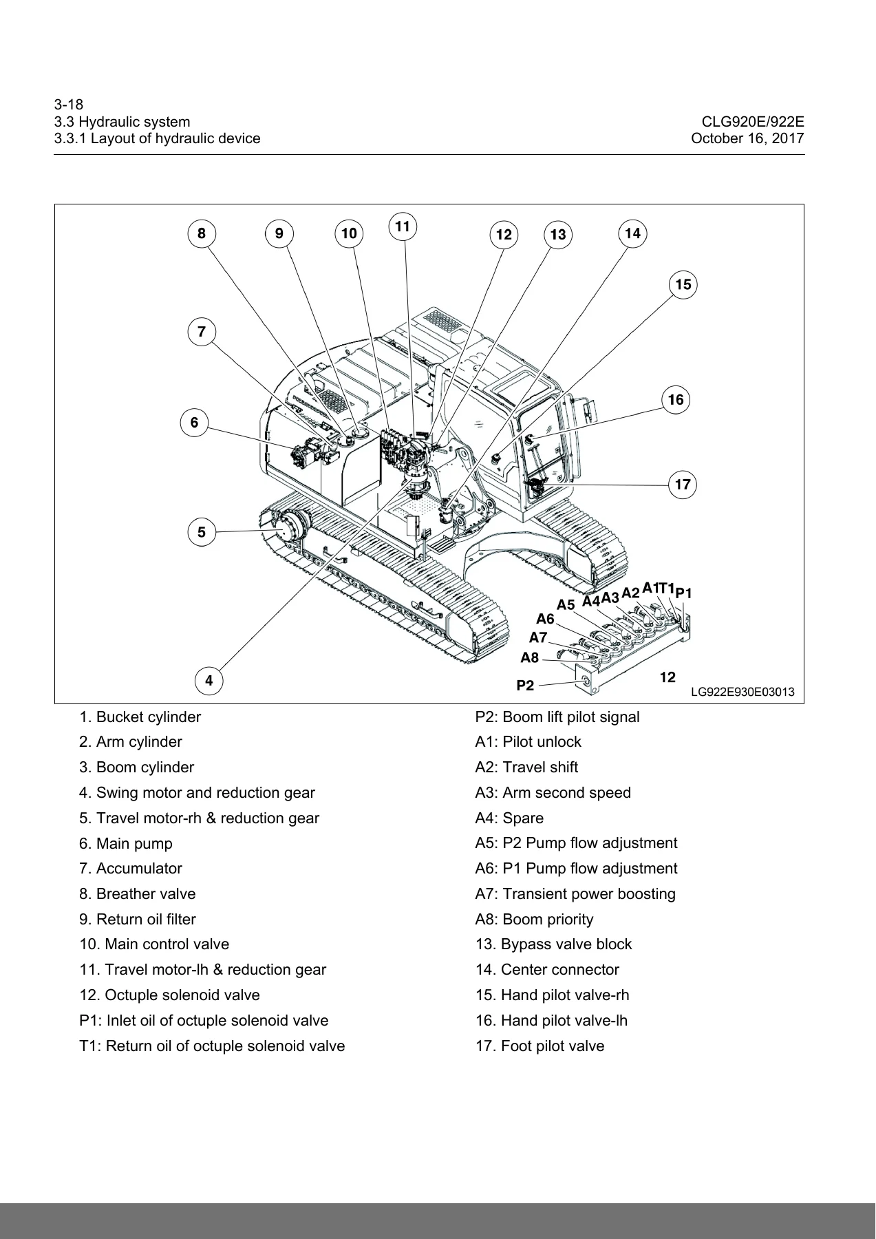
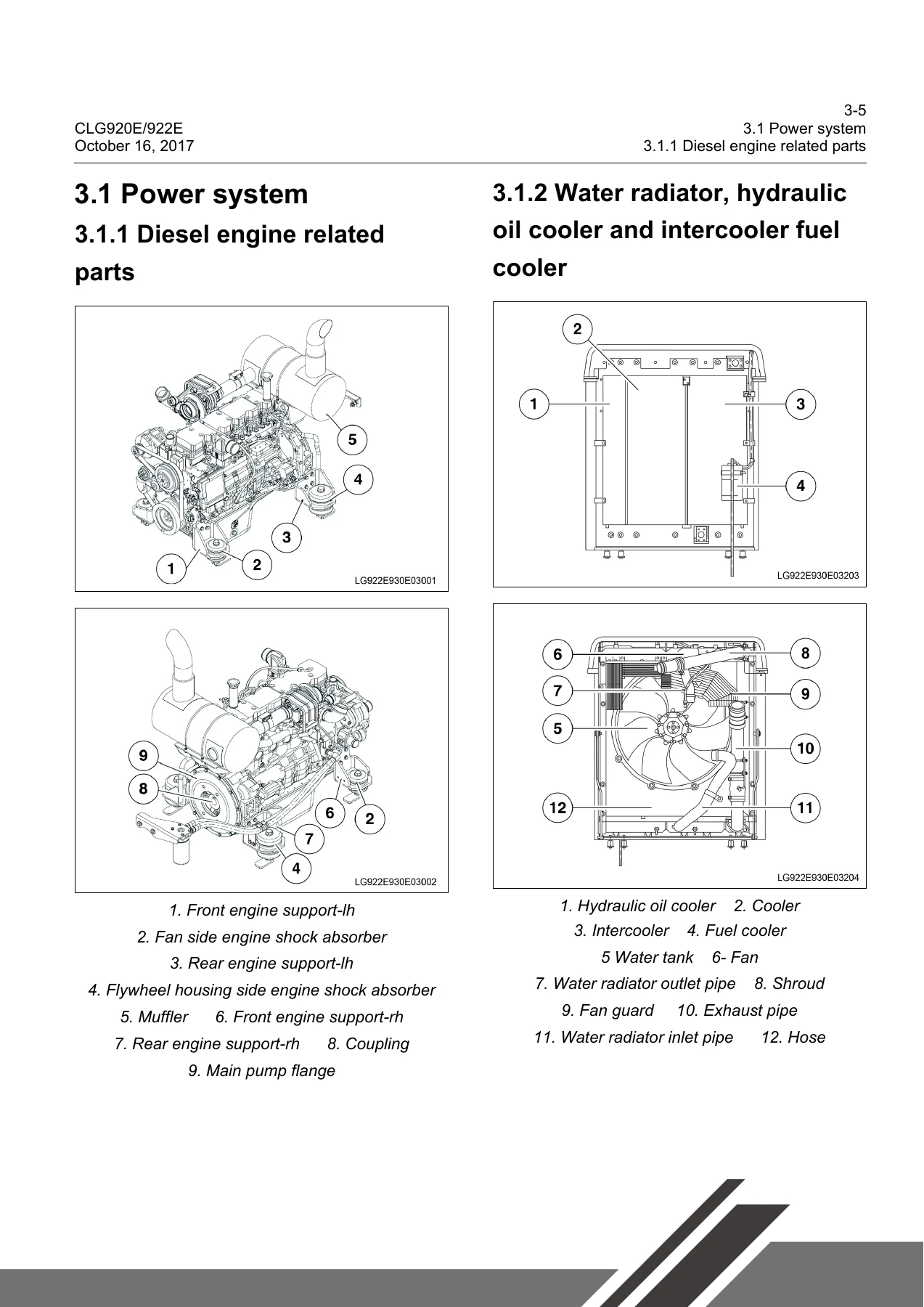
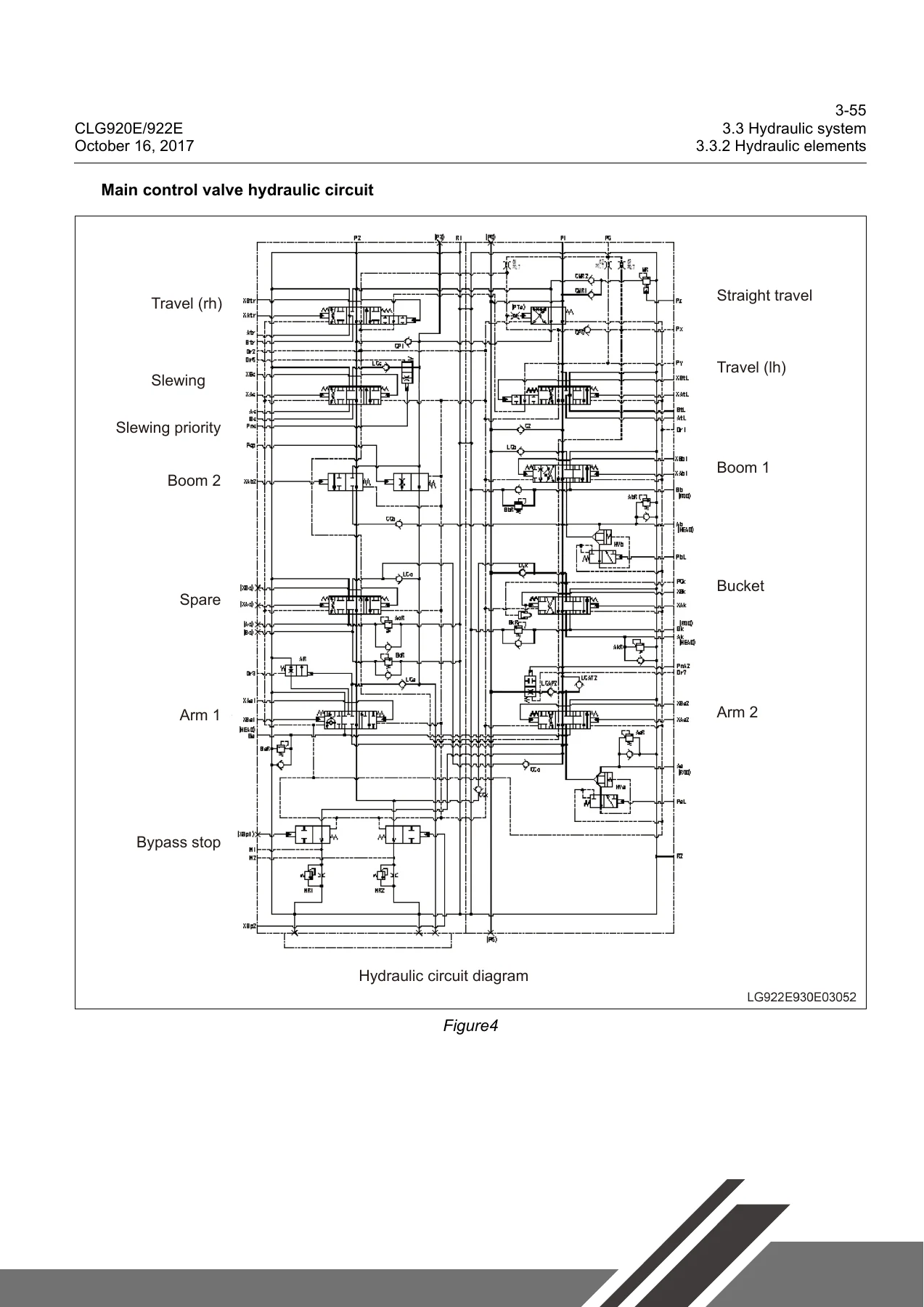
LiuGong CLG920E CLG922E Hydraulic Excavator Service Manual 2017 — PDF page 56 preview
LiuGong CLG920E CLG922E Hydraulic Excavator Service Manual 2017 — PDF page 43 preview
LiuGong CLG920E CLG922E Hydraulic Excavator Service Manual 2017 — PDF page 93 preview

The document splits into a technical guide (safety, foreword, structure function and maintenance standards, testing and adjusting, fault diagnosis) and a workshop guide (disassembly and assembly plus the schematic diagrams of the electrical, air conditioning and hydraulic systems). That two-part layout lets a technician move between the theory behind a circuit and the step-by-step teardown of the same component without leaving the file.

What Each Chapter Delivers

Safety and Foreword

Opening chapters establish the working rules before any tool is picked up — handling high-pressure hydraulic oil, accumulator nitrogen, asbestos, battery electrolyte, hot coolant and oil, plus crane and lifting safety. The foreword supplies the general torque table, unit conversion chart, cable identification method, coating and sealant list, weight table of major components, and the oil specifications and change intervals used throughout the rest of the book.

Structural Function and Maintenance

This chapter walks the machine system by system. The power system section covers the diesel engine related parts and the water radiator, hydraulic oil cooler, intercooler and fuel cooler. The undercarriage section details the track frame and tensioner, idler, carrier roller, track roller, sprocket, track and swing bearing with wear limits and repair-or-replace criteria. The hydraulic system section is the largest part of the CLG920E CLG922E service manual, covering the main pump, main control valve, center connector, explosion-proof valve, hand and foot pilot valves, cushion valve, octuple solenoid valve, travel motor and reduction gear, swing motor and reduction gear, cylinders, hydraulic oil tank and the complete hydraulic working principle for boom, arm, bucket, swing and travel circuits. Work implement, A/C system and electrical system sections complete the chapter.

Parameters and Test and Adjustment

The parameters chapter lists basic dimensions, diesel engine performance data and complete machine performance standards for both CLG920E and CLG922E. The test and adjustment chapter provides the measured procedures with tools, machine status and acceptable values — engine speed, travel speed, travel deviation, swing brake angle and speed, swing bearing clearance, cylinder action times, cylinder settlement, lever forces and strokes, pilot pressures, secondary pilot pressures, relief valve setting pressures, valve lash, crankcase blow-by, oil pressure, track tension and the negative flow feedback pressures N1 and N2.

Fault Diagnosis

The fault diagnosis chapter is built around the machine’s DTC list, with entry after entry giving the system description, consequences, component location, and a numbered step-by-step troubleshooting path using a multimeter. Electrical system faults (E1 through E23) cover battery problems, auto slowdown, engine start and shutdown faults, display and gauge issues, wiper, alarm and air conditioning alarms. Hydraulic and mechanical faults (H1 through H13) walk through slewing brake angle, pump noise, unresponsive operations, oil emulsification, oil temperature rise, swing and travel faults, slow or weak work implement action and engine stall.

Complete PDF Bookmark Tree

Complete Bookmarks

The complete bookmarks in the “LiuGong CLG920E CLG922E Hydraulic Excavator Service Manual 2017” are as follows:

1 Safetyp. 5
1.1 Safety precautionsp. 8
Compressed airp. 10
High-pressure solutionp. 10
Safe disposal of waste liquidp. 11
Precautions for accumulatorp. 12
Asbestosp. 12
Prevention of extruding or cutting offp. 13
Prevention of burnsp. 14
Coolantp. 14
Oilp. 14
Batteryp. 15
Protection for fire and explosionp. 15
Diethyl etherp. 16
Piping, pipe and hosep. 16
Fire extinguisher and first-aid kitp. 17
Prevention of injured by thunderp. 17
Cab protectorp. 18
Top guard and front guardp. 18
Measures in emergencyp. 18
Inner space of cabp. 18
Precautions for accessoriesp. 19
1.2 Precautions for lifting and matching operationsp. 20
Precautions for operating mobile cranep. 21
Precautions for operating bridge cranep. 21
Selection of ropep. 22
2 Forewordp. 23
2.1 How to read the Manualp. 25
2.2 Marking of revised versionp. 26
2.3 Standard of general torquep. 27
2.4 Unit conversion tablep. 31
2.5 Cable identification methodsp. 32
2.6 Coating materialsp. 35
2.7 Weight tablep. 36
2.8 Oils use specificationsp. 37
3 Structural function and maintenancep. 39
3.1 Power systemp. 43
3.1.1 Diesel engine related partsp. 43
3.1.2 Water radiator, hydraulic oil cooler and intercooler fuel coolerp. 43
3.2 Undercarriage systemp. 44
3.2.1 Track frame and tensionerp. 44
3.2.2 Idlerp. 46
3.2.3 Carrier rollerp. 48
3.2.4 Track rollerp. 50
3.2.5 Sprocketp. 52
3.2.6 Trackp. 53
3.2.7 Swing bearingp. 54
3.3 Hydraulic systemp. 55
3.3.1 Layout of hydraulic devicep. 55
3.3.2 Hydraulic elementsp. 57
3.3.2.1 Main pump asp. 57
3.3.2.2 Main control valvep. 73
3.3.2.3 Center connectorp. 129
3.3.2.4 Explosion-proof valvep. 131
3.3.2.5 Hand pilot valvep. 133
3.3.2.6 Foot pilot valvep. 136
3.3.2.7 Cushion valvep. 140
3.3.2.8 Octuple solenoid valvep. 144
3.3.2.9 Travel motor & reduction gearp. 146
3.3.2.10 Swing motor & reduction gearp. 160
3.3.2.11 Cylinderp. 175
3.3.2.12 Hydraulic oil tank asp. 178
3.3.3 Hydraulic working principlep. 182
3.3.3.1 Main hydraulic circuitp. 182
3.3.3.2 Pilot circuitp. 188
3.3.3.3 Negative flow control circuit (with the control spool in the neutral)p. 190
3.3.3.4 Negative flow control circuit (with the control spool moving)p. 192
3.3.3.5 Boom up working circuitp. 194
3.3.3.6 Boom down working circuitp. 196
3.3.3.7 Arm out working circuitp. 198
3.3.3.8 Arm in working circuit (with regeneration)p. 200
3.3.3.9 Arm in working circuit (with no regeneration)p. 202
3.3.3.10 Bucket in working circuitp. 204
3.3.3.11 Bucket out working circuitp. 206
3.3.3.12 Left swing working circuitp. 208
3.3.3.13 Swing priority circuitp. 210
3.3.3.14 Right swing working circuitp. 212
3.3.3.15 Forward travel (high speedp. 215
3.3.3.16 Backward travel (low speed)p. 219
3.3.3.17Bilateral travel and boom rising compound operating circuitp. 223
3.4 Work implementp. 225
3.4.1 Sizes of componentsp. 225
3.4.2 Arm partp. 228
3.4.3 Bucket partp. 231
3.5 Air conditioning systemp. 233
3.5.1 Layout diagram of A/C pipelinep. 233
3.6 Electrical systemp. 234
3.6.1 Engine controlp. 234
3.6.2 Display systemp. 235
3.6.2.1 Yongqing displayp. 236
3.6.2.2 Pike displayp. 253
3.6.3 Electrical control systemp. 267
3.6.3.1 Work modep. 267
3.6.3.2 Automatic idling functionp. 268
3.6.3.3 Transient power boosting functionp. 270
3.6.3.4 Overheating protection functionp. 272
3.6.3.5 Travel speed control functionp. 273
3.6.3.6 Various componentsp. 274
3.6.4 Descriptions of partial circuitsp. 286
3.6.4.1 Travel 2-speed circuitp. 286
3.6.4.2 Transient pressure boosting circuitp. 287
3.6.4.3 Start circuitp. 288
3.6.4.4 Digging function circuitp. 290
3.6.4.5 Flattening function circuitp. 291
3.6.4.6 Charge circuitp. 292
3.6.4.7 Working circuit of pump proportional solenoid valvep. 293
4 Parametersp. 295
4.1 Basic parametersp. 297
4.2 Performance parameters of diesel enginep. 304
4.3 Performance parameters of complete machinep. 305
5 Test and Adjustmentp. 309
5.1 Performance test of complete machinep. 311
5.1.1 Diesel engine speedp. 312
5.1.2 Travel speed (idling speed)p. 312
5.1.3 Running Speed (Actual Measurement Speed)p. 313
5.1.4 Travel Deviationp. 315
5.1.5 Swing Service Brake Anglep. 316
5.1.6 Swing Speedp. 318
5.1.7 Swing Bearing Clearancep. 319
5.1.8 Action Time of Cylinderp. 320
5.1.9 Cylinder Settlementp. 323
5.1.10 Operating Force of Control Leverp. 324
5.1.11 Control Lever Strokep. 325
5.1.12 Boom Lifting and Swing Actionp. 325
5.1.13 Pilot Pressurep. 326
5.1.14 Secondary Pilot Pressurep. 327
5.1.15 Output pressure of solenoid proportional valvep. 329
5.1.16 Setting Pressure of Main Relief Valvep. 330
Attached listp. 333
5.2 Other Testsp. 336
5.2.1 Adjustment of valve lashp. 336
5.2.2 Measurement of blow-by of crankcasep. 345
5.2.3 Measurement of Oil Pressurep. 355
5.2.4 Measurement and Adjustment of Track Tensionp. 359
5.2.5 Inspection and adjustment of minus feedback pressure N1p. 361
5.2.6 Inspection and adjustment of minus feedback pressure N2p. 362
5.2.7 Release the Residual Pressure in Hydraulic Oil Linesp. 363
5.2.8 Exhaust of Various Devicesp. 365
5.2.9 Check for diodep. 368
5.2.10 Adjustment of compressor belt tensionerp. 369
5.2.11 Performance test of travel motors and reduction gearsp. 370
6 Fault diagnosisp. 373
6.1 Precautions for fault diagnosisp. 379
6.2 Basic fault detection before maintenancep. 380
6.3 Classification of faultsp. 383
6.4 Fault Codep. 385
6.4.1 DTC 101001 Extremely low battery voltagep. 385
6.4.2 DTC 101003 High battery voltagep. 394
6.4.3 DTC 101017 Low battery voltagep. 399
6.4.4 DTC 111001 System charging faultp. 408
6.4.5 DTC 121015 Oil pressure switch disconnectedp. 411
6.4.6 DTC 121018 Low Oil Pressurep. 415
6.4.7 DTC 121305 Handle pressure switch OFFp. 418
6.4.8 DTC 121405 Pedal pressure switch disconnectedp. 423
6.4.9 DTC 121604 Air filter switch shorted to groundp. 428
6.4.10 DTC 121615 Air filter cloggingp. 431
6.4.11 DTC 131000 High engine speedp. 434
6.4.12 DTC 131005 Engine speed sensor faultp. 437
6.4.13 DTC 131100 Extremely high coolant temperaturep. 441
6.4.14 DTC 131103 Coolant temperature sensor voltage above the range valuep. 444
6.4.15 DTC 131104 Coolant temperature sensor voltage below the range valuep. 447
6.4.16 DTC 131115 High coolant temperaturep. 450
6.4.17 DTC 131116 High coolant temperaturep. 453
6.4.18 DTC 1131200 Extremely high hydraulic oil temperaturep. 456
6.4.19 DTC 131203 Hydraulic oil temperature sensor voltage above the range valuep. 459
6.4.20 DTC 131204 Hydraulic oil temperature sensor voltage below the range valuep. 462
6.4.21 DTC 131215 High hydraulic oil temperaturep. 465
6.4.22 DTC 131216 Extremely high hydraulic oil temperaturep. 468
6.4.23 DTC 131303 Fuel level sensor voltage above the range valuep. 471
6.4.24 DTC 131304 Fuel level sensor shorted to groundp. 478
6.4.25 DTC 131317 Low fuel levelp. 484
6.4.26 DTC 131603 Water-in-fuel sensor voltage above the range valuep. 488
6.4.27 DTC 131604 Water-in-fuel sensor voltage below the range valuep. 491
6.4.28 DTC 131605 Water-in-fuel sensor open-circuitedp. 494
6.4.29 DTC 131615 Water in fuelp. 497
6.4.30 DTC 131703 Sensor power (5V)-to-battery short circuitp. 500
6.4.31 DTC 131704 Sensor power (5V) shorted to the groundp. 503
6.4.32 DTC 141005 Pump proportional solenoid valve feedback open- circuitedp. 507
6.4.33 DTC 141006 Pump proportional solenoid feedback overcurrentp. 511
6.4.34 DTC 141104 Pump proportional solenoid valve shorted to groundp. 515
6.4.35 Fault Code 141105 Pump proportional solenoid valve open-circuited or short-circuited to the batteryp. 519
6.4.36 DTC 151004 Attachment confluence solenoid valve shorted to groundp. 523
6.4.37 DTC 151005 attachment confluent solenoid valve open-circuited or shorted to the batteryp. 527
6.4.38 DTC 151204 A2 Travel speed solenoid shorted to groundp. 531
6.4.39 DTC 151205 A2 Travel speed solenoid open-circuited or shorted to the batteryp. 536
6.4.40 DTC 151304 A3 Flattening solenoid valve shorted to groundp. 541
6.4.41 DTC 151305 A3 Travel speed solenoid valve open-circuited or shorted to the batteryp. 546
6.4.42 DTC 151404 A8 Trenching solenoid valve shorted to the groundp. 551
6.4.43 DTC 151405 A8 Trenching solenoid valve open-circuited or shorted to the batteryp. 556
6.4.44 DTC 151504 A5 Flow adjusting solenoid shorted to the groundp. 561
6.4.45 DTC 151505 A5 flow adjusting solenoid valve open-circuited or shorted to the batteryp. 565
6.4.46 DTC 151605 A6 Flow adjusting solenoid open-circuited or shorted to the batteryp. 570
6.4.47 DTC 151704 A7 Power boosting solenoid valve shorted to the groundp. 575
6.4.48 DTC 151705 A7 Power boosting solenoid valve open-circuited or shorted to the batteryp. 580
6.4.49 DTC 151804 A4 Travel lifting solenoid valve shorted to the groundp. 585
6.4.50 DTC 151805 A4 Travel lifting solenoid valve open-circuited or shorted to the batteryp. 590
6.4.51 DTC 151905 A5 or A6 solenoid valve feedback open-circuitedp. 595
6.4.52 DTC 151906 A5 or A6 solenoid valve feedback overcurrentp. 599
6.4.53 DTC 171004 Battery relay shorted to groundp. 603
6.4.54 DTC 171104 Auto preheating relay shorted to the groundp. 606
6.4.55 DTC 171105 Auto preheating relay open-circuited or shorted to the batteryp. 610
6.4.56 DTC 171204 Start cut-off relay shorted to the groundp. 615
6.4.57 DTC 171205 Start cut-off output open-circuited or shorted to the batteryp. 620
6.4.58 DTC 201004 Travel alarm shorted to groundp. 626
6.4.59 DTC 211003 P1 pump pressure sensor voltage above the range valuep. 629
6.4.60 DTC 211004 P1 pump pressure sensor voltage below the range valuep. 634
6.4.61 DTC 211003 P2 pump pressure sensor voltage above the range valuep. 638
6.4.62 DTC 211104 P2 pump pressure sensor voltage below the range valuep. 641
6.4.63 DTC 211203 N1 negative flow pressure sensor voltage above the range valuep. 645
6.4.64 DTC 211204 N1 negative flow pressure sensor voltage below the range valuep. 648
6.4.65 DTC 211303 N2 negative flow pressure sensor voltage above the range valuep. 652
6.4.66 DTC 211304 N2 negative flow pressure sensor voltage below the range valuep. 655
6.4.67 DTC 211316 High N2 negative flow pressurep. 659
6.4.68 DTC 211403 Pump pressure-reducing valve sensor voltage above the range valuep. 662
6.4.69 DTC 231014 CAN bus communication errorp. 665
6.4.70 DTC 221001 Actuator feedback voltage below the range valuep. 668
6.4.71 DTC 221003 Actuator feedback voltage above the range valuep. 672
6.4.72 DTC 221007 Actuator getting stuckp. 676
6.4.73 DTC 221013 Actuator outside the calibrated rangep. 679
6.4.74 DTC 221104 Actuator AC1 shorted to groundp. 684
6.4.75 DTC 221204 Actuator AC2 shorted to groundp. 687
6.4.76 DTC 221305 Actuator AC1 open-circuitedp. 690
6.4.77 DTC 221306 Actuator AC1 overcurrentp. 693
6.4.78 DTC 221405 Actuator AC2 terminal open-circuitedp. 697
6.4.79 DTC 221406 Actuator AC2 overcurrentp. 700
6.4.80 DTC 231012 Abnormal controller heartbeatp. 704
6.4.81 DTC 231014 CAN bus communication errorp. 707
6.4.82 DTC 241014 accelerator knob outside the measurement rangep. 710
6.4.83 DTC 251004 Fuel pump relay shorted to groundp. 714
6.4.84 DTC 251005 Fuel pump relay open-circuited or shorted to the batteryp. 718
6.4.85 DTC 261011GPS antenna faultp. 723
6.4.86 DTC 261111GPS module faultp. 726
6.4.87 DTC 261211 GSM signal faultp. 727
6.4.88 DTC 261311 GPRS connection faultp. 730
6.4.89 DTC 261411 SIM card read faultp. 730
6.4.90 DTC 261512 Abnormal GPS heartbeatp. 732
6.4.91 DTC 261611 automatic locking level 1 abnormal GPS heartbeat, the machine is limited for usep. 735
6.4.92 DTC 261614 forced locking level 1 payment expired, the machine is limited for usep. 738
6.4.93 DTC 261711 automatic locking level 2 abnormal GPS heartbeat, and the machine is prohibited for usep. 739
6.4.94 DTC 261714 forced locking level 2 payment expired, and the machine is prohibited for usep. 742
6.4.95 DTC 261814 Please pay the due loan on timep. 743
6.4.96 DTC 271304 Fan reversing solenoid valve shorted to groundp. 744
6.4.97 Fault Code 271305 Pump proportional solenoid valve open-circuited or short-circuited to the batteryp. 747
6.4.98 DTC 271404 Fan drive solenoid valve shorted to the groundp. 751
6.4.99 Fault Code 271405 Fan drive solenoid valve open-circuited or short- circuited to the batteryp. 754
6.4.100 DTC 271505 Fan drive solenoid valve feedback open-circuitedp. 758
6.4.101 DTC 271506 Fan drive solenoid valve feedback overcurrentp. 761
6.5 Fault Diagnosis of Electrical Systemp. 764
6.5.1 Troubleshooting solution for E1-battery power lossp. 764
6.5.2 E2Troubleshooting for battery abnormityp. 766
6.5.3 E3 Automatic slowdown failedp. 769
6.5.4 E4 Engine cannot be startedp. 773
6.5.5 E5-Engine shuts down during operationp. 786
6.5.6 E6 Engine cannot be shut downp. 791
6.5.7 E7 Preheater does not workp. 795
6.5.8 E8 All the work implements, revolving and traveling cannot movep. 801
6.5.9 E9 Display panel showing nothingp. 807
6.5.10 E10 Incorrectly displayed hydraulic oil temperaturep. 812
6.5.11 E11 Fuel gauge cannot display correctlyp. 815
6.5.12 E12 Windshield wiper out of workp. 823
6.5.13 E13 Travel alarm unable to soundp. 828
6.5.14 E14 A/C panel unable to displayp. 831
6.5.15 E15 A/C no wind or abnormal air volumep. 836
6.5.16 E16 Poor A/C refrigerationp. 839
6.5.17 E17 air conditioning abnormal alarm E11–Inner gas sensor break linep. 843
6.5.18 E18 air conditioning abnormal alarm E12–Inner gas sensor short circuitp. 845
6.5.19 E19 air conditioning abnormal alarm E15–water temperature sensor break linep. 847
6.5.20 E20 air conditioning abnormal alarm E16–water temperature sensor short circuitp. 849
6.5.21 E21 air conditioning abnormal alarm E18–solar sensor short circuitp. 851
6.5.22 E22 air conditioning abnormal alarm E43–Air blowing valve abnormalp. 853
6.5.23 E23 Abnormal alarm of the A/C E44 – Abnormal air mixing doorp. 855
6.6 Fault diagnosis of the hydraulic system and mechanical systemp. 857
6.6.1 System table of the hydraulic system and mechanical systemp. 857
6.6.2 H1-Excessive barking angle for slewing stopp. 858
6.6.3 H2-Abnormal noise of pump mounting positionp. 859
6.6.4 H3-No responses for all operations when starting the enginep. 860
6.6.5 H4-Hydraulic oil emulsificationp. 861
6.6.6 H5-Abnormal hydraulic oil temperature risep. 862
6.6.7 H6-Slewing abnormally to left and right directionsp. 863
6.6.8 H7-No response for slewing single direction operationp. 864
6.6.9 H8-Rotation unable to stopp. 865
6.6.10 H9-Fail to actuate unilateral travel mechanismp. 866
6.6.11 H10-Travel deviationp. 867
6.6.12 H11-Slow speed of the boom, arm or bucketp. 868
6.6.13 H12-Weak actions of the boom, arm or bucketp. 869
6.6.14 H13-Significantly reduced engine speed or engine stallingp. 870
7 Removal and Installationp. 871
7.1 Overviewp. 873
7.2 Power Systemp. 873
7.2.1 Removal and installation of diesel engine assemblyp. 873
7.2.2 Removal and installation of the hydraulic oil coolerp. 881
7.2.3 Removal and installation of the intercoolerp. 885
7.2.4 Removal and installation of water radiatorp. 888
7.2.5 Removal and installation of the diesel tank assemblyp. 892
7.2.6 Removal and installation of the injectorp. 895
7.2.7 Removal and installation of the engine front sealp. 900
7.2.8 Removal and installation of the engine rear sealp. 906
7.2.9 Removal and installation of the cylinder head assemblyp. 914
7.2.10 Removal and installation of the fuel coolerp. 918
7.3 Track Travel Systemp. 919
7.3.1 Removal and installation of the track rollerp. 919
7.3.2 Removal and installation of the carrier rollerp. 921
7.3.3 Removal and installation of the track assemblyp. 923
7.3.4 Removal and installation of the sprocketp. 925
7.3.5 Removal and installation of the idler assembly and tensioner assemblyp. 926
7.3.6 Removal and installation of the revolving framep. 928
7.3.7 Removal and installation of the swing bearingp. 930
7.4 Covering Partsp. 932
7.4.1 Removal and installation of the engine hoodp. 932
7.4.2 Removal and installation of the counterweightp. 934
7.5 Hydraulic Systemp. 936
7.5.1 Removal and installation of center connector assemblyp. 936
7.5.2 Disassembly and assembly of the center jointp. 939
7.5.3 Removal and installation of hydraulic oil tankp. 943
7.5.4 Removal and installation of main control valve assemblyp. 947
7.5.5 Disassembly and assembly of the main control valvep. 951
7.5.6 Removal and installation of main pump assemblyp. 968
7.5.7 Removal and Installation of main pump assemblyp. 972
7.5.8 Removal and Installation of the Travel Pilot Valve Assemblyp. 989
7.5.9 Disassembly and assembly of travel pilot valvep. 992
7.5.10 Removal and installation of hand pilot valve assemblyp. 1016
7.5.11 Disassembly and assembly of the hand pilot valve assemblyp. 1019
7.5.12 Removal and installation of the travel motor & reduction gearp. 1037
7.5.13 Disassembly and assembly of travel motor & reduction gear assemblyp. 1042
(1) Assembly of control valvep. 1070
(2) Assembly of reduction gear and hydraulic motorp. 1076
[A] Adjustment of ball bearingp. 1085
Tool(s)p. 1085
[B] Adjust the axial clearance of cone bearing.p. 1086
Tool(s) :p. 1086
7.5.14 Removal and installation of the swing motor & reduction gearp. 1092
7.5.15 Disassembly and assembly of the swing motor & reduction gearp. 1096
7.6 Work Implementp. 1124
7.6.1 Removal and installation of the bucketp. 1124
7.6.2 Removal and installation of link and leverp. 1127
7.6.3 The removal and installation of armp. 1130
7.6.4 Removal and Installation of the Boomp. 1132
7.6.5 Removal and installation of the work implement assemblyp. 1137
7.6.6 Removal and installation of bucket cylinder assemblyp. 1141
7.6.7 Removal and installation of arm cylinder assemblyp. 1144
7.6.8 Removal and installation of boom cylinder assemblyp. 1147
7.6.9 Disassembly and assembly of cylinderp. 1151
7.7 A/C Systemp. 1161
7.7.1 Removal and installation of A/C compressor assemblyp. 1161
7.7.2 Removal and installation of A/C evaporator assemblyp. 1164
7.8 Cabp. 1170
7.8.1 Removal and installation of cabp. 1170
7.8.2 Removal and installation of floor frame assemblyp. 1175
8 Attached Drawingp. 1179

Removal and Installation

The removal and installation chapter provides the exact teardown and reassembly sequence for the diesel engine, hydraulic oil cooler, intercooler, water radiator, fuel tank, injector, engine seals, cylinder head, fuel cooler, track system components, revolving frame, swing bearing, engine hood, counterweight, center connector, hydraulic oil tank, main control valve, main pump, travel pilot valve, hand pilot valve, travel and swing motor assemblies, bucket, link and lever, arm, boom, work implement assembly, the three cylinders and cylinder internals, A/C compressor and evaporator, and the cab and floor frame. Tightening torques, thread locker notes and lifting weights are stated at the relevant steps.

Fault Code Coverage

Over one hundred DTC entries are documented, including 101001 extremely low battery voltage, 101003 high battery voltage, 101017 low battery voltage, 111001 system charging fault, 121015 oil pressure switch disconnected, 121018 low oil pressure, 121305 handle pressure switch OFF, 121405 pedal pressure switch disconnected, 121604 air filter switch shorted to ground, 121615 air filter clogging, 131000 high engine speed, 131005 engine speed sensor fault, the coolant and hydraulic oil temperature codes, 131303/131304/131317 fuel level codes, 131603 through 131615 water-in-fuel codes, 131703/131704 sensor power faults, 141005 through 141105 pump proportional solenoid valve codes, the 151xxx attachment, travel, flattening, trenching, flow adjusting and power boosting solenoid valve codes, 171004 through 171205 battery and preheating relay codes, 201004 travel alarm, 211003 through 211403 pressure sensor codes, 221xxx actuator codes, 231012/231014 controller and CAN bus codes, 241014 accelerator knob, 251004/251005 fuel pump relay codes, 261xxx GPS, GSM, GPRS and SIM codes, and 271304 through 271506 fan reversing and fan drive solenoid valve codes.

Hydraulic and Electrical Schematics

The attached drawing chapter closes the LiuGong CLG920E CLG922E hydraulic excavator service manual with the full hydraulic schematic diagram, the electric schematic diagram and the A/C electrical schematic diagram. These fold-out style schematics let a technician trace a circuit or oil path from the pump to the actuator or from the battery to a sensor without needing a separate drawing set.

Who This Manual Is For

This LiuGong CLG920E CLG922E service manual is written for the trained technician, the workshop supervisor and the owner-operator who wants factory-level procedures rather than guesswork. Because it includes the standard torque table, oil specifications, wear limits, service data, fault code flowcharts, and the schematic diagrams all in one document, it works as both a repair guide and a reference book that can be kept open on the bench through a full teardown.

Get the LiuGong CLG920E CLG922E Service Manual

With this LiuGong CLG920E CLG922E Hydraulic Excavator Service Manual you can diagnose a fault code with the correct test points, set a relief valve to the right pressure, rebuild a travel or swing motor, reseal a cylinder, adjust track tension, or pull and reinstall the main pump — following LiuGong procedures and values rather than approximations. Getting the procedures and specifications right the first time protects the machine, avoids repeat labour and prevents damage caused by incorrect torque or clearance. The file is delivered as an instant PDF download with no shipping, ready to open on a laptop, tablet or phone and to print pages for the workshop floor.
Reviews

There are no reviews yet.

Be the first to review “LiuGong CLG920E CLG922E Hydraulic Excavator Service Manual 2017”

What Our Customers Say

★★★★★ Live reviews from customers
Loading customer reviews...
0
    0
    Your Cart
    Your cart is emptyReturn to Shop
    🛒
    Recently Purchased
    🕒 verified order