
Hyundai HX300L HX300NL Crawler Excavator Service Repair Manual
Original price was: $39.95.$23.95Current price is: $23.95.
Workshop service manual for the Hyundai HX300 L and HX300 NL crawler excavators, covering structure, hydraulics, electrics, CAPO mechatronics, troubleshooting, performance tests, and component overhaul including Long Reach and High Walker configurations.
Description
Hyundai HX300L HX300NL Crawler Excavator Service Repair Manual
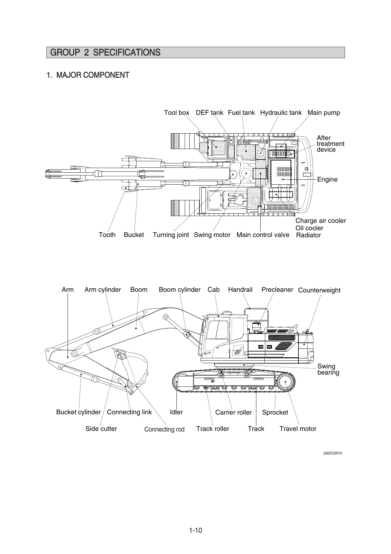
This Hyundai HX300L HX300NL Crawler Excavator Service Repair Manual is the shop-level reference used to understand, diagnose, and rebuild the HX300 series crawler. It walks through the machine as a complete system: Cummins QSB6.7 powerplant and aftertreatment, tandem main pumps and 10-spool main control valve, swing and travel reductions, pilot RCV controls, 24 V electrics, and the ADVANCED CAPO computer-aided power optimization suite that ties engine ECM and pump EPPR together. Configurations documented in the specification groups include the standard HX300 L, the narrower HX300 NL, the 6.25 m two-piece boom arrangement, HX300 L Long Reach with the 10.2 m boom and 7.85 m arm, and HX300 L High Walker.
File Details
- Manual type: Service manual (workshop / shop manual)
- Brand / models: Hyundai HX300 L, HX300 NL, HX300 L Long Reach, HX300 L High Walker
- Language: English
- Page count: 820
- File format: PDF
Machine Coverage and Major Specifications
The specification group lists operating weights of 30200 kg (66580 lb) for the standard HX300 L on 600 mm shoes, 30000 kg (66140 lb) for HX300 NL, 33210 kg (73220 lb) for the 6.25 m two-piece boom machine, 33070 kg (72910 lb) for Long Reach on 800 mm shoes, and 33040 kg (72840 lb) for High Walker. Standard SAE heaped bucket capacity is 1.27 m3 (1.66 yd3) except Long Reach at 0.52 m3 (0.68 yd3). Travel speed is 3.3 / 5.9 km/hr, swing speed 10.2 rpm, gradeability 35 degrees (70%), and maximum traction force 26500 kg (58420 lb).
The engine table names a Cummins QSB6.7 4-cycle turbocharged, charge-air-cooled, water-cooled diesel: 6 cylinders in-line, firing order 1-5-3-6-2-4, direct injection, 107 x 124 mm bore and stroke, 6700 cc displacement, 17.3:1 compression. Rated net output is 230 Hp (171 kW) at 1950 rpm SAE J1349; rated gross is 242 Hp (180 kW) SAE J1995; peak torque is 100.9 kgf.m (729.8 lbf.ft) at 1500 rpm. High idle is 1950 +/- 50 rpm and low idle 800 +/- 100 rpm. Starting motor is Denso 24 V-4.8 kW, alternator Denso 24 V-95 A, batteries 2 x 12 V x 160 Ah.
Hydraulic hardware is specified as variable-displacement tandem axial piston main pumps at 2 x 140 cc/rev, 350 kgf/cm2 (4980 psi) main relief with 380 kgf/cm2 (5400 psi) power-boost, and rated flow 2 x 273 l/min. The pilot gear pump is 15 cc/rev at 40 kgf/cm2. The main control valve is a 10-spool hydraulic-pilot unit. Swing motor is a 156.9 cc/rev axial piston unit with 300 kgf/cm2 relief and two-stage planetary reduction. Travel motors are variable 282.6 / 156.9 cc/rev with 350 kgf/cm2 relief. Cylinder sizes include boom 140 x 1465 mm, arm 150 x 1765 mm, bucket 135 x 1185 mm, and Long Reach bucket 100 x 870 mm.
Fluid capacities printed in the recommended-oils chart: engine oil 23.1 l, DEF/AdBlue tank 42.5 l, swing drive 11 l, final drives 7.8 l x 2, hydraulic tank 190 l / system 330 l, fuel tank 500 l, radiator 40 l. Electrical and mechatronics pages split connector maps, cluster wiring, and several diagnostic trees at serial -#1094 versus #1095-.
Chapters Covered
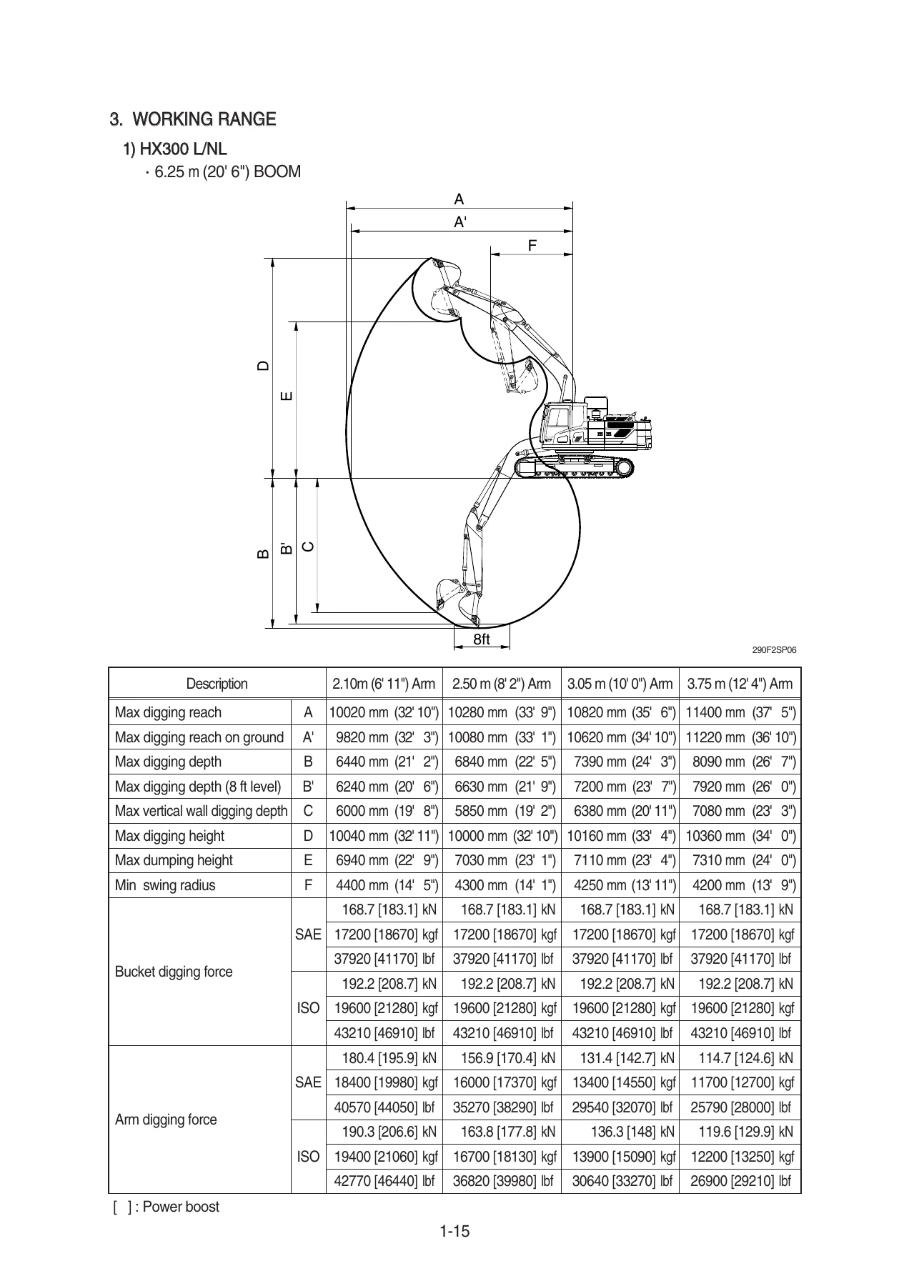
- Section 1 General – Group 1 Safety hints; Group 2 Specifications (major components, dimensions, working range, weights, lifting capacities, bucket guide, undercarriage, engine/pump/valve/motor/cylinder data, recommended oils)
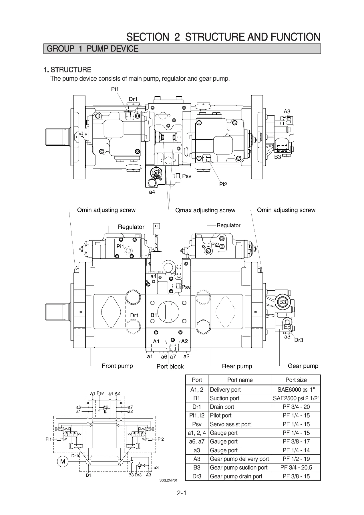
- Section 2 Structure and Function – Group 1 Pump device; Group 2 Main control valve; Group 3 Swing device; Group 4 Travel device; Group 5 RCV lever; Group 6 RCV pedal
- Section 3 Hydraulic System – Group 1 Hydraulic circuit; Group 2 Main circuit; Group 3 Pilot circuit; Group 4 Single operation; Group 5 Combined operation
- Section 4 Electrical System – Group 1 Component location; Group 2 Electric circuit; Group 3 Electrical component specification; Group 4 Connectors
- Section 5 Mechatronics System – Outline; Mode selection; Automatic deceleration; Power boost; Travel speed control; Automatic warming up; Engine overheat prevention; Variable power control; Attachment flow control; Boom floating; Intelligent power control; Anti-restart; Self-diagnostic system; Engine control; EPPR valve; Monitoring system; Fuel warmer
- Section 6 Troubleshooting – Before troubleshooting; Hydraulic and mechanical system; Electrical system; Mechatronics system
- Section 7 Maintenance Standard – Operational performance test; Major components; Track and work equipment
- Section 8 Disassembly and Assembly – Precaution; Tightening torque; Pump device; Main control valve; Swing device; Travel device; RCV lever; Turning joint; Boom, arm and bucket cylinder; Undercarriage; Work equipment
- Section 9 Component Mounting Torque – Introduction guide; Engine system; Electric system; Hydraulic system; Undercarriage; Structure; Work equipment
Taken together, those sections give a technician the theory of each major assembly, the oil-flow path for every single and combined function, the CAPO logic that sets P/S/E/U power modes and EPPR power-shift, fault-code tables for both the machine MCU and the Cummins ECM (J1939 SPN/FMI), measured performance limits, and the removal-to-rebuild sequence for the pumps, valve, swing and travel units, cylinders, turning joint, undercarriage, and front attachment.
How the Shop Manual Is Meant to Be Used
The foreword states the book was prepared so a serviceman can understand the product and judge repairs correctly in a workshop. Safety symbols flag pressurized work and quality-critical steps. Conversion tables cover mm/in, kg/lb, litres/gallons, kgf.m to lbf.ft, kgf/cm2 to lbf/in2, and Fahrenheit-Centigrade so values can be read in either unit system. Safety Group 1 covers tagging the right-hand control with a Do Not Operate tag, three-point contact when climbing, parking on level ground with the bucket down and the pilot shutoff locked, relieving hydraulic pressure before cracking lines, searching leaks with cardboard, cooling-system cap discipline, battery acid and explosion precautions, and proper fluid disposal.
Hydraulics, Electrics, and CAPO Control
Structure chapters open the tandem pump (front and rear piston pumps plus gear pump and regulators), name every port, and explode the cylinder block, swash plate, servo piston, and valve plates. The hydraulic-system section then traces suction and delivery, pilot supply, and the oil path for boom, arm, bucket, swing, and travel both alone and in combination. Electrical pages locate switches and relays in the cab, print multi-sheet circuit diagrams split by serial range, list connector part numbers (AMP, Deutsch, Tyco), and specify starter, charging, lighting, and wiper circuits.
Mechatronics coverage is unusually complete for this class of book. ADVANCED CAPO coordinates engine and pump so selected work uses less fuel. Documented functions include three power modes with a 10-step multimodal dial, auto deceleration to 1100 rpm after 4 seconds of lever-neutral and 1000 rpm after one minute, power boost, two-speed travel, automatic warm-up below 30 C coolant for up to 10 minutes, overheat derate above coolant/oil temperature limits, variable power versus RCV stroke, attachment flow control, boom float, intelligent power control, starter anti-restart, cluster self-diagnosis with active and logged MCU/ECM faults, EPPR current-to-pressure checks, cluster gauges and warning lamps (coolant, hydraulic oil, engine oil pressure, check-engine, DEF/AdBlue, SCR cleaning), ESL password start limit, and the fuel-warmer circuit.
Diagnostics, Tests, and Overhaul
Troubleshooting begins with cluster monitoring of rpm, temperatures, voltage, and pressures, then branches into hydraulic/mechanical trees (no travel, unusual pump noise, attachment drift, slow actuators) and electrical trees (coolant, air-cleaner, oil-pressure, and hydraulic-temperature lamps; no-start). Mechatronics diagnosis covers slow actuators with good engine speed, engine stall, cluster/mode failure, auto-decel failure, and individual pump, negative-control, swing, boom, and arm pressure-sensor faults, plus power-max and boom-priority EPPR and arm-regeneration solenoid checks. Separate trees are printed for serial -#1094 and #1095-.
Section 7 gives the operational performance test method: warm to 50 C coolant and 50 +/- 5 C hydraulic oil, accel dial at 10, then measure start idle (1000 +/- 100 rpm), P mode 1800 +/- 50, S mode 1700 +/- 50, E mode 1600 +/- 50, travel times, swing times, cycle times (boom raise 3.7 +/- 0.4 s on standard HX300 L), cylinder drift, lever effort and stroke, and relief pressures (boom/arm/bucket 350 (380) +/- 10 kgf/cm2, port relief 400 +/- 10). Section 8 sequences removal, air bleed, and reassembly for the pump, MCV, swing motor, travel device, RCV, turning joint, cylinders, undercarriage, and work equipment, with mounting torques such as engine-to-bracket M12 x 1.75 at 11.5 +/- 1.0 kgf.m. Section 9 tabulates component mounting torques across engine, electric, hydraulic, undercarriage, structure, and work-equipment groups and instructs the use of metric fasteners and genuine Hyundai spare parts.
What This Manual Lets You Do
With the Hyundai HX300L HX300NL Crawler Excavator Service Repair Manual on the bench you can set relief and EPPR values to the printed limits, read MCU and Cummins J1939 fault codes instead of swapping parts blindly, time boom/arm/bucket/swing/travel against Section 7 standards, overhaul the tandem pumps and travel/swing reductions, replace cylinders and the turning joint without guessing port sizes, and work the correct serial-split harness when the machine is before or after #1095. Using the published pressures, rpm windows, fluid grades, and torque figures keeps DPF/SCR aftertreatment, pump regulators, and reductions inside the limits the book itself uses as judgement standards.
Delivery is an instant PDF download after payment. There is no printed shipment to wait for. Open the file on a laptop in the shop, a tablet in the cab, or a phone at the machine, and print the pages you need for a specific job.


Reviews
There are no reviews yet.