★ TRUSTED BY 321,897+ PROFESSIONALS WORLDWIDE
🏢
Trusted Business
Verified & Licensed
🛡️
Virus Free Files
100% Safe Downloads
🔒
Secure Payment
SSL Protected
Instant Delivery
Available Immediately
Sale!

LiuGong CLG950E Hydraulic Excavator Service Manual 2019 Cummins QSG Workshop

Original price was: $39.95.Current price is: $24.95.

LiuGong CLG950E hydraulic excavator service manual (201909001, September 3, 2019) covering structure, parameters, testing, fault codes, and R&I for Cummins QSG / QSG12 / X12 machines.

Instant PDF Download
Available immediately
💾
Save to Your Device
Download & keep forever
🛡️
Antivirus Scanned
100% virus-free
🌍
Trusted Worldwide
175,000+ customers

Description

Workshop coverage for the CLG950E

This LiuGong CLG950E Hydraulic Excavator Service Manual 2019 Cummins QSG Workshop is the shop reference written for the CLG950E hydraulic excavator with Cummins QSG power (EPA Tier 4f / EU Stage IV / EU Stage V). Publication number 201909001 is dated September 3, 2019. The book walks a technician from safety and basic service data through component function, machine parameters, performance tests, fault-code diagnosis, and full removal and installation of the major assemblies.

The applicable type and model printed on the title page is CLG950E. Parameter tables list the diesel as Cummins QSG12 / Cummins X12: six-cylinder, turbocharged, air-to-air intercooled, water-cooled, 132 mm × 144 mm bore and stroke, 11.8 L displacement, 17:1 compression, ignition order 1-5-3-6-2-4. Rated power is given as 298 kW (400 HP) at 2100 r/min, with maximum torque 2034 N·m at 1400 r/min. Operating weight is 47000/48000 kg, standard bucket 2.2 m³, travel 0–5.5 / 0–3.3 km/h, swing 8.5 r/min, gradeability 35° (70%).

File Details

  • Manual type: Service Manual
  • Brand / model: LiuGong CLG950E hydraulic excavator
  • Engine family: Cummins QSG (QSG12 / X12), EPA Tier 4f / EU Stage IV / EU Stage V
  • Language: English
  • Page count: 1068
  • File format: PDF
  • Document number: 201909001
  • Publication date on section headers: September 3, 2019

Chapters Covered

  • 1 Safety Tips — Safety precautions; precautions for lifting and matching operations
  • 2 Basics — How to read the manual; marking of revised version; general torque specifications; unit conversion table; cable identification methods; coating materials; weight table; oils use specifications
  • 3 Structure Function and Maintenance — Power system (diesel-related parts; water radiator, hydraulic oil cooler, intercooler and fuel cooler); undercarriage (track frame and tensioner, idler, carrier roller, track roller, sprocket, track, swing bearing); hydraulic system (layout, hydraulic elements, working principle); work implement maintenance references; A/C system; electrical system (engine control, display, electrical control, partial circuits)
  • 4 Parameters — Basic parameters; performance parameters of the diesel engine; performance parameters of the complete machine
  • 5 Testing and Adjustment — Complete-machine performance tests (engine speed, travel and running speed, travel deflection, swing brake angle and speed, swing-bearing clearance, cylinder action time and settlement, control-lever force and stroke, boom lift and swing, pilot and secondary pilot pressure, solenoid proportional-valve output, main-relief setting); other tests (crankcase blow-by, track tension, minus-feedback pressures N1/N2, residual-pressure release, device exhaust, diode check, travel motor and reduction-gear performance)
  • 6 Fault diagnosis — Precautions and basic detection; fault classification; numbered fault codes (battery, charging, pilot switches, air filter, hydraulic-oil temperature, fuel level, water-in-fuel, 5 V sensor power, pump and attachment solenoids, travel/flattening/trenching/flow/power-boost valves, relays, pump and negative-flow pressure sensors, CAN/controller, accelerator, GPS/GSM/GPRS locking, fan solenoids); electrical-system faults E1–E11 and related items; hydraulic and mechanical fault trees (including hydraulic-oil emulsification and abnormal oil-temperature rise)
  • 7 Removal and Installation — Power system (engine assembly, coolers, radiator, diesel tank, injectors, seals, cylinder head); undercarriage (rollers, track, sprocket, idler and tensioner, revolving frame, swing bearing); covering parts (hood, counterweight); hydraulic system (center swivel, tank, main control valve, main and fan pumps, travel and hand pilot valves, travel and swing motor/reduction gears, fan valve and motor, attachment-swing pump and valve); work implement (bucket, link and lever, arm, boom, cylinders); A/C compressor and evaporator; cab and floor plate
  • 8 Attached drawing — Pump part drawing; hydraulic system schematic; electrical schematic; A/C system schematic

IMAGES PREVIEW

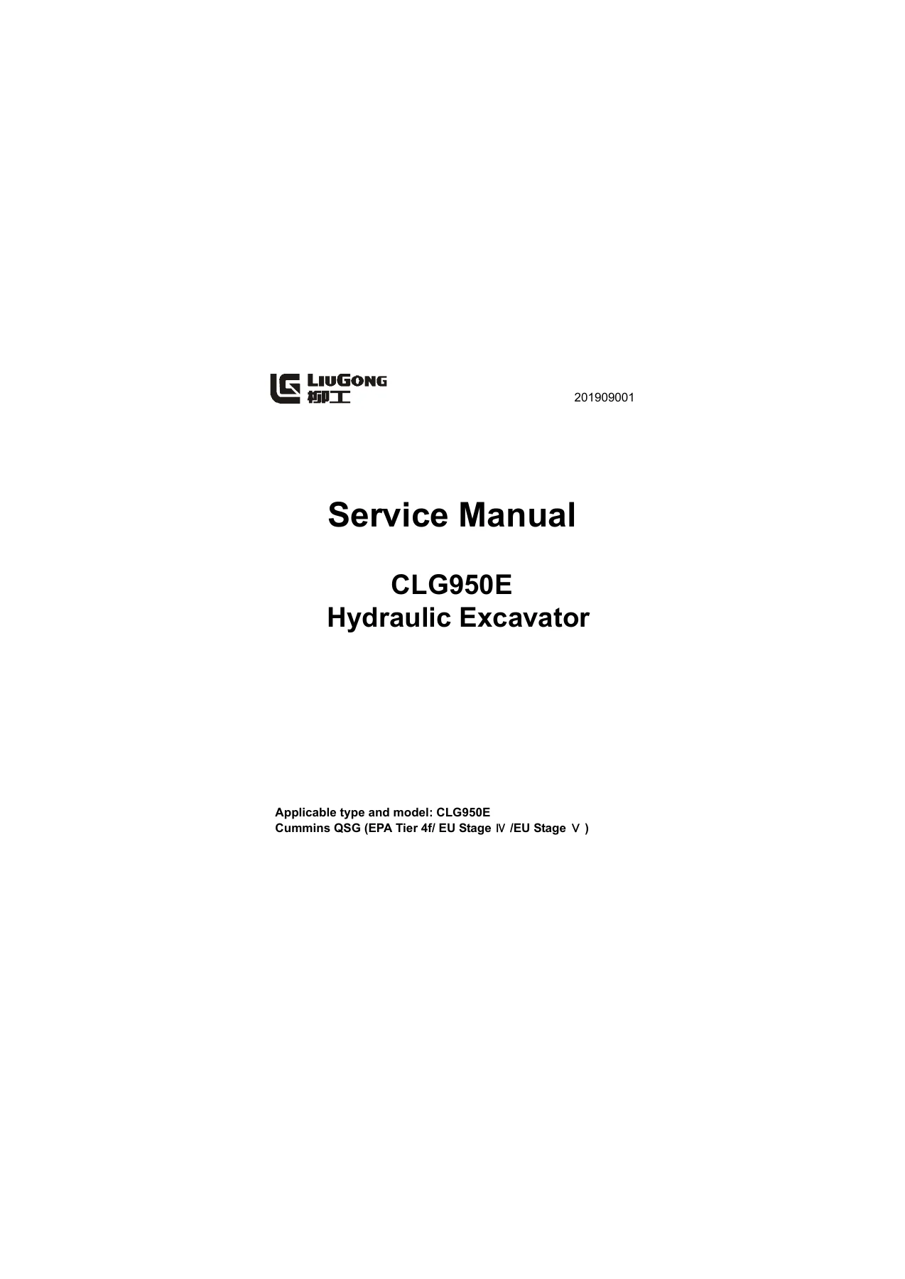
LiuGong CLG950E Hydraulic Excavator Service Manual 2019 Cummins QSG Workshop — PDF page 1 preview
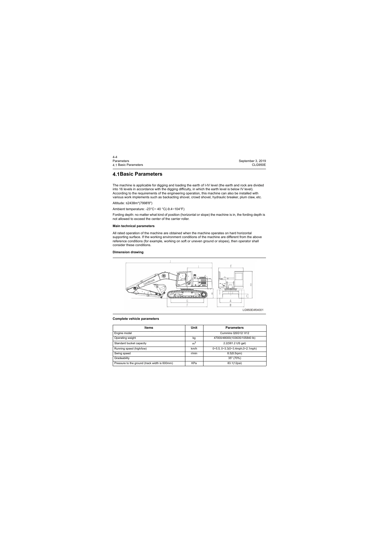
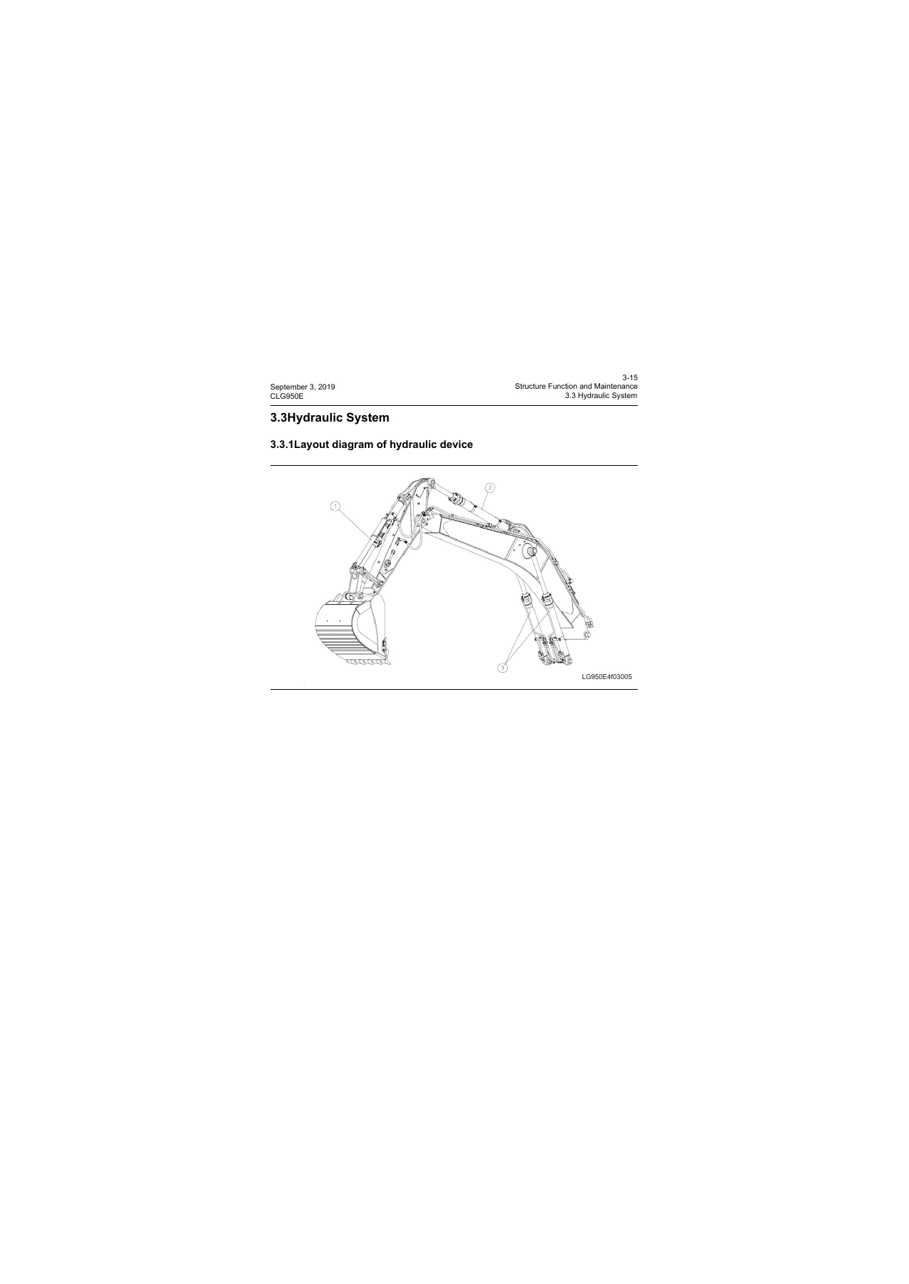
LiuGong CLG950E Hydraulic Excavator Service Manual 2019 Cummins QSG Workshop — PDF page 294 preview
LiuGong CLG950E Hydraulic Excavator Service Manual 2019 Cummins QSG Workshop — PDF page 51 preview

Taken together, the LiuGong CLG950E Hydraulic Excavator Service Manual 2019 Cummins QSG Workshop is a single-machine shop book: it explains how each major system is built and how oil flows, then gives the numbers a bench or field tech uses to judge wear, set pressures, and put assemblies back together without guessing.

Safety, fluids, and fastening data

Chapter 1 treats high-pressure hydraulic oil, accumulators charged with nitrogen only, hot coolant and oil, battery electrolyte, fire and explosion around fuel and wiring, cab guards, and lifting practice (sling angle, wire-rope selection table, signalman rules). Chapter 2 collects workshop constants that appear again during R&I: captive-bolt torques such as M24-10.9 engine-shock and swing-bearing bolts at 1020 N·m, M20-10.9 radiator-frame and swing-reduction bolts at 600 N·m, M42-10.9 counterweight bolts at 460 N·m, plus separate tables for 24° cone O-ring hose connectors, flange hose bolts, and thread-angle connectors.

The weight table is written for crane and sling selection: engine assembly 1000 kg, hydraulic pump 267.5 kg, radiator assembly 383 kg, hydraulic tank (empty) 272 kg, revolving frame 3575 kg, counterweight 9000 kg, boom 3637 kg, arm 1516 kg, track frame 5950 kg, and matching cylinder and roller masses. Oils use specifications list change intervals and fill volumes — engine oil 500 h / 37.8 L, swing-reduction gear oil 1000 h / 14 L, travel-reduction gear oil 1000 h / 15 L × 2, hydraulic oil 2000 h with tank 290 L and system 520 L, cooling system 2000 h / 50 L — and viscosity grades by ambient temperature (API CH-4 engine oils, ISO VG 32/46/68 hydraulic oils, SAE 85W-140 swing and 80W-90 travel gear oils, molybdenum-disulfide lithium grease 2# on pins and the swing bearing).

How the machine is built

Structure Function and Maintenance is the longest technical block. Power-system pages identify DPF and engine mounts, then the stacked cooler package (fuel radiator, hydraulic-oil radiator, shroud, intercooler). Undercarriage coverage gives construction and wear notes for the track frame, tensioner, idler, carrier and track rollers, sprocket, shoes, and swing bearing.

The hydraulic chapter starts with a layout of tank, main pump, fan pump, gear pump, main control valve, octuple solenoid valve, pilot valves, and actuators, then moves into element data and circuit logic. Examples printed in the text include swing motor M5X130CHB at 129.2 cm³/rev with rated 32.4 MPa and maximum 39.2 MPa; gear pump PGF517 at 19 ml/rev; boom / arm / bucket relief at 38.2 ± 0.5 MPa; main-pump flow 2 × 380 L/min; main-relief setting 32.3 MPa with instantaneous supercharge 35.3 MPa; swing-motor relief 28 MPa; travel-motor safety 32.3 MPa; pilot circuit 3.9 MPa. Cylinder sizes are given as boom 2-φ165 × φ115 × 1560 mm, arm 1-φ190 × φ130 × 1980 mm, bucket 1-φ170 × φ120 × 1260 mm. Working-principle pages describe center-bypass and parallel-passage flow for travel, arm, boom, bucket, and swing, plus boom-priority, main overflow, anti-cavitation, hose-burst balance valves, travel-motor brake valves, and the hydraulic fan circuit that varies flow with oil, coolant, and ambient temperature.

Work-implement notes cover boom, arm, and bucket service limits. The electrical section describes engine control, the cab display (hour meter, hydraulic-oil temperature gauge, and related indicators), controller inputs such as hydraulic-oil temperature and level, pump current and fan-speed signals, overheating protection levels (hydraulic oil above 86 °C or coolant above 102 °C at level 1), and CAN communication between engine and main controllers. Air-conditioning data includes 5000 W cooling / 5800 W heating, R134a 950 ± 50 g, and Denso 10S15C compressor with ND-OIL8.

Numbers used on the job

Chapter 4 of the LiuGong CLG950E Hydraulic Excavator Service Manual 2019 Cummins QSG Workshop records complete-vehicle dimensions (overall length 11515 mm, width 3340 mm on 600 mm shoes, height 3810 mm, cab roof 3307 mm, tail swing radius 3640 mm, track gauge 2740 mm) and working-range figures for a 7060 mm boom with 2900 mm arm: maximum digging height 10618 mm, dump height 7578 mm, digging depth 7380 mm, digging radius 11585 mm, bucket digging force 287 kN, arm digging force 263 kN. Electrical system voltage is 24 V with two 12 V batteries, starter 24 V-7.5 kW, alternator 24 V-70 A.

Complete PDF Bookmark Tree

Complete Bookmarks

The complete bookmarks in the “LiuGong CLG950E Hydraulic Excavator Service Manual 2019 Cummins QSG Workshop” are as follows:

Applicable type and model: CLG950E Cummins QSG (EPA Tier 4f/ EU Stage Ⅳ/EU Stage Ⅴ)p. 1
Contentsp. 3
1 Safety Tipsp. 5
Important Safety Informationp. 7
1.1 Safety Precautionsp. 8
1.2 Precautions for Llifting and Matching Operationsp. 17
2 Basicsp. 21
2.1 How to Read the Manualp. 23
2.2 Marking of Revised Versionp. 25
2.3 General Torque Specificationsp. 26
2.4 Unit Conversion Tablep. 29
2.5 Cable Identification Methodsp. 30
2.6 Coating Materialsp. 32
2.7 Weight Tablep. 33
2.8 Oils Use Specificationsp. 34
3 Structure Function and Maintenancep. 37
3.1 Power Systemp. 39
3.1.1 Diesel engine related partsp. 39
3.1.2 Water radiator, hydraulic oil cooler and intercooler fuel coolerp. 40
3.2 Undercarriage Systemp. 41
3.2.1 Track frame and tensionerp. 41
3.2.2 Idlerp. 43
3.2.3 Carrier rollerp. 44
3.2.4 Track rollerp. 46
3.2.5 Sprocketp. 48
3.2.6 Trackp. 49
3.2.7 Swing bearingp. 50
3.3 Hydraulic Systemp. 51
3.3.1 Layout diagram of hydraulic devicep. 51
3.3.2 Hydraulic elementp. 53
Main pump assemblyp. 53
Main Control Valvep. 73
Center connectorp. 121
Explosion-proof valvep. 124
Hand pilot valvep. 127
Foot pilot valvep. 129
Buffering valve (optional)p. 133
Octuple solenoid valvep. 136
Travel Motor & Reduction Gearp. 139
Swing motor & reduction gearp. 161
Cylinderp. 175
Hydraulic oil tankp. 178
Fan pump assembly structurep. 181
PTO Pumpp. 187
3.3.3 Hydraulic working principlep. 190
Main hydraulic circuitp. 190
Pilot circuitp. 195
Negative flow control circuit (with the control spool in the neutral)p. 196
Negative flow control circuit (with the control of spool moving)p. 198
Boom rising working circuitp. 200
Boom descending working circuitp. 202
Arm stretching working circuitp. 204
Arm withdrawing working circuit (with regeneration)p. 206
Arm withdrawing working circuit (with no regeneration)p. 208
Bucket withdrawing working circuitp. 210
Bucket stretching working circuitp. 212
Left swing working loopp. 214
Right swing working loopp. 216
Rotating priority pipeline (rotating opposite arm priority function)p. 218
Travel forward (fast)p. 220
Travel backward (slow)p. 223
Bilateral travel and boom rising compound operationp. 226
Fan hydraulic systemp. 228
Single-way working circuit of breaking hammerp. 230
Attachment swing system (Left swing)p. 232
Attachment swing system (Right swing)p. 234
3.4 Work Implementp. 236
3.4.1 Maintenance references of main partsp. 236
3.4.2 Maintenance references of arm partp. 239
3.4.3 Maintenance references of bucket partp. 242
3.5 A/C Systemp. 244
3.6 Electrical Systemp. 245
3.6.1 Engine controlp. 245
3.6.2 Display systemp. 246
Displayp. 247
LCD part of displayp. 249
Display button panelp. 251
User menup. 256
3.6.3 Electrical control systemp. 264
Work modep. 264
Automatic idling functionp. 265
Transient power boosting functionp. 266
Overheating protection functionp. 267
Traveling speed control functionp. 268
3.6.4 Descriptions of partial circuitsp. 278
Travel 2-speed circuitp. 278
Transient pressure boosting circuitp. 279
Start circuitp. 280
Trenching function circuitp. 282
Flattening function circuitp. 283
Charge circuitp. 284
Working circuit of pump proportional solenoid valvep. 284
Wiper working circuitp. 285
Counterweight loading and unloading work circuitp. 287
Variable speed fan work circuitp. 288
Attachment swing work circuitp. 289
Attachment opening and closing work circuitp. 290
4 Parametersp. 291
4.1 Basic Parametersp. 294
4.2 Performance Parameters of Diesel Enginep. 300
4.3 Performance Parameters of Complete Machinep. 301
5 Testing and Adjustmentp. 305
5.1 Performance Test of Complete Machinep. 307
5.1.1 Diesel engine speedp. 308
5.1.2 Travel speed (idling speed)p. 308
5.1.3 Measurement of running speed (actual measurement speed)p. 309
5.1.4 Travel deflectionp. 310
5.1.5 Swing service brake anglep. 311
5.1.6 Swing speedp. 313
5.1.7 Swing bearing clearancep. 314
5.1.8 Action time of cylinderp. 315
5.1.9 Cylinder settlementp. 318
5.1.10 Operating force of control leverp. 319
5.1.11 Control lever strokep. 319
5.1.12 Boom lifting and swing actionp. 319
5.1.13 Pilot pressurep. 320
5.1.14 Secondary pilot pressurep. 321
5.1.15 Output pressure of solenoid proportional valvep. 323
5.1.16 Setting pressure for main relief valvep. 324
5.2 Other Testsp. 329
5.2.1 Measurement of blow-by of crankcasep. 331
5.2.2 Measurement and adjustment of track tensionp. 338
5.2.3 Inspection and adjustment of minus feedback pressure N1p. 339
5.2.4 Inspection and adjustment of minus feedback pressure N2p. 341
5.2.5 Release of remaining pressure in hydraulic oil linesp. 342
5.2.6 Exhaust of various devicesp. 343
5.2.7 Inspection procedures of diodep. 345
5.2.8 Performance test of travel motors and reduction gearsp. 346
6 Fault diagnosisp. 349
6.1 Precautions for Fault Diagnosisp. 353
6.2 Basic Fault Detection Before Maintenancep. 353
6.3 Classification of Faultsp. 356
6.4 Fault Codep. 358
6.4.1 Fault code 101001 Extremely low battery voltagep. 358
6.4.2 Fault code 101003 High battery voltagep. 366
6.4.3 Fault code 101017 Low battery voltagep. 370
6.4.4 DTC 111001 System charging faultp. 378
6.4.5 Fault code 121305 Hand pilot pressure switch OFFp. 381
6.4.6 DTC 121405 Foot pilot pressure switch OFFp. 386
6.4.7 Fault Code 121604 Air filter switch shorted to groundp. 391
6.4.8 Fault Code 121615 Air filter cloggingp. 394
6.4.9 Fault Code 131200 Extremely high hydraulic oil temperaturep. 396
6.4.10 Fault Code 131203 Hydraulic oil temperature sensor voltage above the range valuep. 398
6.4.11 Fault Code 131204 Hydraulic oil temperature sensor voltage below the range valuep. 401
6.4.12 Fault Code 131215 High hydraulic oil temperaturep. 405
6.4.13 Fault Code 131216 Extremely high hydraulic oil temperaturep. 407
6.4.14 Fault Code 131303 Fuel level sensor voltage above the range valuep. 409
6.4.15 Fault Code 131304 Fuel level sensor shorted to groundp. 415
6.4.16 Fault code 131317 Low fuel levelp. 421
6.4.17 Fault Code 131603 Water-in-fuel sensor voltage above the range valuep. 425
6.4.18 Fault Code 131604 Water-in-fuel sensor voltage below the range valuep. 428
6.4.19 Fault Code 131605 Water-in-fuel sensor open-circuitp. 431
6.4.20 Fault code 131615 Water-in-fuelp. 434
6.4.21 Fault code 131703 Sensor power (5V) shorted to the power supply of the complete machinep. 436
6.4.22 Fault Code 131704 Sensor power (5V)shorted to groundp. 439
6.4.23 Fault Code 141005 Pump proportional solenoid valve feedback open-circuitp. 443
6.4.24 Fault Code 141006 Pump proportional solenoid valve feedback overcurrentp. 446
6.4.25 Fault Code 141104 Pump proportional solenoid valve shorted to groundp. 449
6.4.26 Fault code 141105 Pump proportional solenoid valve open-circuit or shorted to the power supplyp. 452
6.4.27 Fault Code 151004 Attachment confluence solenoid valve shorted to groundp. 455
6.4.28 Fault code 151005 attachment confluent solenoid valve open- circuit or shorted to the power supplyp. 458
6.4.29 Fault Code 151204 A2 Travel shift solenoid shorted to groundp. 461
6.4.30 Fault code 151205A2 Travel shift solenoid valve open-circuit or shorted to the power supplyp. 465
6.4.31 Fault Code 151304 A3 Flattening solenoid valve shorted to groundp. 469
6.4.32 Fault code 151305 A3 Flattening shift solenoid valve open-circuit or shorted to the power supplyp. 473
6.4.33 Fault Code 151404 A8 Trenching solenoid valve shorted to the groundp. 477
6.4.34 Fault code 151405 A8 Digging solenoid valve open-circuit or shorted to the power supplyp. 481
6.4.35 Fault Code 151504 A5 Flow adjusting solenoid shorted to groundp. 485
6.4.36 Fault code 151505 A5 flow adjusting solenoid valve open-circuit or shorted to the power supplyp. 488
6.4.37 Fault code 151605 A6 Flow adjusting solenoid valve open-circuit or shorted to the power supplyp. 492
6.4.38 Fault Code 151704 A7 Power boosting solenoid valve shorted to the groundp. 496
6.4.39 Fault code 151705 A7 Transient power boosting solenoid valve open-circuit or shorted to the power supplyp. 500
6.4.40 Fault Code 151804 A4 Travel lifting solenoid valve shorted to the groundp. 504
6.4.41 Fault code 151805A4 Travel lifting solenoid valve open-circuit or shorted to the power supplyp. 508
6.4.42 Fault Code 151905 A5 or A6 solenoid valve feedback open- circuitedp. 512
6.4.43 Fault Code 151906 A5 or A6 solenoid valve feedback overcurrentp. 515
6.4.44 DTC 171004 Short circuit to ground of battery relayp. 518
6.4.45 Fault Code 171104 Auto preheating relay shorted to the groundp. 521
6.4.46 Fault code 171105 Auto preheating relay open circuit or shorted to the power supplyp. 524
6.4.47 Fault Code 171204 Start cut-off relay shorted to groundp. 528
6.4.48 Fault code 171205 Start cut-off output open circuit or shorted to the power supplyp. 532
6.4.49 Fault Code 201004 Traveling alarm shorted to groundp. 537
6.4.50 Fault Code 211003 P1 pump pressure sensor voltage above the range valuep. 540
6.4.51 Fault code 211004 P1 pump pressure sensor voltage below the range valuep. 544
6.4.52 Fault Code 211003 P2 pump pressure sensor voltage above the range valuep. 548
6.4.53 Fault code 211104 P2 pump pressure sensor voltage below the range valuep. 552
6.4.54 Fault Code 211203 N1 negative flow pressure sensor voltage above the range valuep. 556
6.4.55 Fault Code 211204 N1 negative flow pressure sensor voltage below the range valuep. 559
6.4.56 Fault Code 211303 N2 negative flow pressure sensor voltage above the range valuep. 563
6.4.57 Fault Code 211304 N2 negative flow pressure sensor voltage below the range valuep. 566
6.4.58 Fault Code 211316 High N2 negative flow pressurep. 570
6.4.59 Fault Code 231012 Abnormal controller heartbeatp. 572
6.4.60 Fault Code 231014 CAN bus communication errorp. 575
6.4.61 Fault Code 241014 accelerator knob outside the measurement rangep. 578
6.4.62 Fault Code 251004 Fuel pump relay shorted to groundp. 581
6.4.63 Fault code 251005 Fuel pump relay open circuit or shorted to the power supplyp. 585
6.4.64 Fault code 261011GPS antenna faultp. 589
6.4.65 Fault Code 261111GPS module faultp. 591
6.4.66 Fault code 261211GSM signal faultp. 592
6.4.67 Fault Code 261311 GPRS connection faultp. 594
6.4.68 Fault Code 261411 SIM card read faultp. 595
6.4.69 Fault code 261512 Abnormal GPS heartbeatp. 597
6.4.70 Fault Code 261611 automatic locking level 1 GPS abnormal heartbeat, limited machinep. 600
6.4.71 Fault Code 261614 command locking level 1 payment expired, limited machinep. 603
6.4.72 Fault Code 261711 automatic locking level 2 GPS abnormal heartbeat,limited machinep. 604
6.4.73 Fault Code 261714 command locking level 2 payment expired, limited machinep. 607
6.4.74 Fault Code 261814 Please pay the due loan timelyp. 608
6.4.75 Fault code 271304 Fan reversing solenoid valve shorted to groundp. 609
6.4.76 Fault Code 271305 Fan reversing solenoid valve open-circuited or short-circuited to the power supplyp. 612
6.4.77 Fault Code 271404 Fan drive solenoid valve shorted to the groundp. 615
6.4.78 Fault code 271405 Fan drive solenoid valve open circuit or shorted to the power supplyp. 618
6.4.79 Fault Code 271505 Fan drive solenoid valve feedback open- circuitedp. 621
6.4.80 Fault Code 271506 Fan drive solenoid valve feedback overcurrentp. 624
6.5 Fault Diagnosis of the Electrical Systemp. 627
6.5.1E1 Troubleshooting solution for battery power lossp. 627
6.5.2 E2 Troubleshooting solution for abnormal batteryp. 629
6.5.3 E3 Automatic slowdown failedp. 632
6.5.4 E4 Engine cannot be startedp. 636
6.5.5 E5 Engine cut-out during operationp. 646
6.5.6 E6 Engine cannot be shut downp. 650
6.5.7 E7 Pre-heater does not workp. 653
6.5.8 E8 All the work implements, revolving and traveling cannot movep. 659
6.5.9 E9 Display panel showing nothingp. 664
6.5.10 E10 Incorrectly displayed hydraulic oil temperaturep. 668
6.5.11 E11 Fuel gauge unable to display correct valuep. 670
6.5.12 E12 Windshield wiper failsp. 677
6.5.13 E13 Travel alarm unable to soundp. 683
6.5.14 E14 A/C panel unable to displayp. 687
6.5.15 E15-No wind or abnormal air volume of air conditionerp. 692
6.5.16 E16 Poor A/C refrigerationp. 695
6.5.17 E17 air conditioning abnormal alarm E11–Inner gas sensor break linep. 698
6.5.18 E18 air conditioning abnormal alarm E12–Inner gas sensor short circuitp. 700
6.5.19 E19 air conditioning abnormal alarm E15–water temperature sensor break linep. 702
6.5.20 E20 air conditioning abnormal alarm E16–water temperature sensor short circuitp. 704
6.5.21 E21 air conditioning abnormal alarm E18–solar sensor short circuitp. 706
6.5.22 E22 air conditioning abnormal alarm E43–Air blowing valve abnormalp. 708
6.5.23 E23 Abnormal alarm of the A/C E44 – Abnormal air mixing doorp. 710
6.6 Fault Diagnosis of the Hydraulic System and Mechanical Systemp. 712
6.6.1 System table of the hydraulic system and mechanical systemp. 712
6.6.2 H1 Excessive barking angle for slewing stopp. 713
6.6.3 Abnormal noise from H2 pump mounting positionp. 714
6.6.4 H3 Start the engine, and all operations have no responsep. 715
6.6.5 H4 Hydraulic oil emulsificationp. 716
6.6.6 H5 Abnormal hydraulic oil temperature risep. 717
6.6.7 H6 Slewing abnormally to left and right directionsp. 718
6.6.8 H7 No response for slewing single direction operationp. 719
6.6.9 H8 Rotation unable to stopp. 720
6.6.10 H9 Fail to actuate unilateral travel mechanismp. 721
6.6.11 H10 Travel deviationp. 722
6.6.12 H11 Slow speed of the boom, arm or bucketp. 723
6.6.13 H12 Weak actions of the boom, arm or bucketp. 724
6.6.14 H13 Significantly reduced engine speed or engine stallingp. 725
6.6.15 H14 Abnormal fan speedp. 725
7 Removal and Installationp. 727
7.1 Overviewp. 729
7.2 Power Systemp. 729
7.2.1 Removal and installation of diesel engine assemblyp. 729
7.2.2 Removal and installation of the hydraulic oil coolerp. 740
7.2.3 Removal and installation of the intercoolerp. 744
7.2.4 Removal and installation of water radiatorp. 748
7.2.5 Removal and installation of the diesel tank assemblyp. 752
7.2.6 Removal and installation of the fuel coolerp. 756
7.2.7 Removal and installation of the fuel injectorp. 757
7.2.8 Removal and installation of the engine front sealp. 760
7.2.9 Removal and installation of the engine rear sealp. 762
7.2.10 Removal and installation of the cylinder head assemblyp. 765
7.3 Undercarriage Systemp. 769
7.3.1 Removal and installation of the track rollerp. 769
7.3.2 Removal and installation of the carrier rollerp. 771
7.3.3 Removal and installation of the track assemblyp. 773
7.3.4 Removal and installation of the sprocketp. 775
7.3.5 Removal and installation of the idler assembly and tensioner assemblyp. 776
7.3.6 Removal and installation of the revolving framep. 778
7.3.7 Removal and installation of the swing bearingp. 780
7.4 Covering Partsp. 781
7.4.1 Removal and installation of the engine hoodp. 781
7.4.2 Removal and installation of the counterweightp. 786
7.5 Hydraulic Systemp. 789
7.5.1 Removal and installation of center swivel jointp. 789
7.5.2 Disassembly and assembly of center revolving jointp. 792
7.5.3 Removal and installation of hydraulic oil tankp. 796
7.5.4 Removal and installation of the main control valve assemblyp. 800
7.5.5 Disassembly and assembly of the main control valve asp. 804
7.5.6 Removal and installation of main pump assembly and fan pump assemblyp. 822
7.5.7 Removal and Installation of main pump assemblyp. 827
7.5.8 Disassembly and assembly of the fan pump asp. 848
7.5.9 Removal and installation of the travel pilot valve assemblyp. 860
7.5.10 Disassembly and assembly of the travel pilot valve assemblyp. 863
7.5.11 Removal and installation of hand pilot valve assemblyp. 888
7.5.12 Disassembly and assembly of the hand pilot valve assemblyp. 890
7.5.13 Removal and installation of the travel motor & reduction gearp. 908
7.5.14 Disassembly and assembly of the travel motor & reduction gearp. 912
7.5.15 Removal and installation of the swing motor & reduction gearp. 954
7.5.16 Disassembly and assembly of the swing motor & reduction gearp. 958
7.5.17 Removal and installation of fan control valvep. 990
7.5.18 Removal and installation of fan motorp. 992
7.5.19 Removal and installation of the gear pump (attachment swing)p. 994
7.5.20 Removal and installation of the valve block assembly (attachment swing)p. 996
7.6 Work Implementp. 999
7.6.1 Removal and installation of the bucketp. 999
7.6.2 Removal and installation of link and leverp. 1002
7.6.3 The removal and installation of armp. 1005
7.6.4 Removal and installation of the boomp. 1008
7.6.5 Removal and installation of the work implement assemblyp. 1013
7.6.6 Removal and installation of the bucket cylinderp. 1017
7.6.7 Removal and installation of arm cylinderp. 1020
7.6.8 Removal and installation of boom cylinderp. 1023
7.6.9 Disassembly and assembly of cylinderp. 1027
7.7 A/C systemp. 1038
7.7.1 Removal and installation of A/C compressor assemblyp. 1038
7.7.2 Removal and installation of A/C evaporator assemblyp. 1042
7.8 Cabp. 1048
7.8.1 Removal and installation of cabp. 1048
7.8.2 Removal and installation of floor plate assemblyp. 1054
8 Attached drawingp. 1057
8.1 Pump Part Drawingp. 1059
8.2 Main Control Valve Part Drawingp. 1060
8.3 Hydraulic System Schematic Diagramp. 1063
8.4 Electrical Schematic Diagramp. 1064
8.5 A/C System Schematic Diagramp. 1065

Complete-machine performance standards include idle speeds 1000 ± 30 / 1950 ± 30 r/min (A/C off), 20 m travel times, swing 21 ± 1.5 s per 3 revolutions, swing-bearing vertical clearance ≤ 0.65 mm, cylinder cycle times, settlement limits, lever forces, pilot 3.9–4.1 MPa at high idle, and main-circuit / port-relief check pressures. Engine-only data adds valve lash (intake 0.36 mm, exhaust 0.69 mm) and thermostat opening 82–88 °C.

Testing, codes, and teardown

Testing and Adjustment tells how to measure those same values in the yard: tools, parking attitude, hydraulic-oil temperature window 45–55 °C (or 50 ± 5 °C for pressure work), and data sheets. Other tests cover crankcase blow-by, track sag, N1/N2 negative-flow pressure, safe release of residual line pressure, bleeding the main pump and travel motors after oil or component work, and travel-motor/reduction-gear performance.

Fault diagnosis begins with pre-checks (oil levels, filters, obvious leaks) then splits into controller fault codes and symptom trees. Codes span charging and battery voltage, clogged air filter, hydraulic-oil temperature sensor range and over-temperature (including 86 °C high and 95 °C extremely high paths), fuel and water-in-fuel sensors, pump proportional solenoids, attachment confluence, travel shift, flattening, trenching, flow adjust, power boost, travel lift, fan drive and reverse, pressure sensors on P1/P2 and N1/N2, CAN heartbeat, and telematics lock states. Electrical symptoms E1–E11 cover a dead battery, no-start, cut-out, failed pre-heater, and dead implements. Hydraulic trees address emulsified oil and abnormal temperature rise by checking level, cooler blockage, and fan drive.

Removal and Installation is written as photographed shop sequences with warnings to ground the implement, dump accumulator pressure, and vent the hydraulic tank before opening lines. Procedures cover the diesel assembly and cooling pack, undercarriage pieces, 9000 kg counterweight, center swivel joint, tank, main valve, pumps, pilot valves, travel and swing drives, fan circuit, attachment-swing gear pump, boom/arm/bucket and their cylinders, A/C compressor and evaporator, and the cab. After reassembly the text sends the tech back to refill, circulate oil, and recheck level and leaks using the torque figures from Basics.

Chapter 8 collects the pump part drawing plus hydraulic, electrical, and A/C schematics used when tracing a circuit that the fault-code chapter has already narrowed.

What you can do with this manual

With the LiuGong CLG950E Hydraulic Excavator Service Manual 2019 Cummins QSG Workshop a shop can plan lifts from the printed component weights, choose oils and change intervals from the specification tables, set main, port, swing, travel, and pilot pressures to the published values, time travel and swing against the Chapter 4 standards, follow a numbered code to a sensor, solenoid, or harness, and remove or rebuild the engine package, pumps, valve, drives, and front-end without relying on memory. Using the printed procedures and limits matters on a 47–48 t machine: wrong relief settings, mixed oil brands, or residual pressure left in a line are exactly the conditions the safety and test chapters warn against.

After payment you receive the PDF immediately — no shipping delay. Open it on a phone, tablet, or workshop PC and print the pages you need at the machine.
Reviews

There are no reviews yet.

Be the first to review “LiuGong CLG950E Hydraulic Excavator Service Manual 2019 Cummins QSG Workshop”

What Our Customers Say

★★★★★ Live reviews from customers
Loading customer reviews...
0
    0
    Your Cart
    Your cart is emptyReturn to Shop
    🛒
    Recently Purchased
    🕒 verified order