★ TRUSTED BY 321,897+ PROFESSIONALS WORLDWIDE
🏢
Trusted Business
Verified & Licensed
🛡️
Virus Free Files
100% Safe Downloads
🔒
Secure Payment
SSL Protected
Instant Delivery
Available Immediately
Sale!

LiuGong CLG920D 921Di 922D Hydraulic Excavator Service Manual January 2021

Original price was: $37.95.Current price is: $21.95.

LiuGong service manual for CLG920D, CLG921Di and CLG922D hydraulic excavators with Cummins B5.9 and QSB7 engines. Covers structure, parameters, testing, fault diagnosis, removal and installation, plus hydraulic and electrical drawings. Document 202101002, January 4, 2021, 764 pages.

Instant PDF Download
Available immediately
💾
Save to Your Device
Download & keep forever
🛡️
Antivirus Scanned
100% virus-free
🌍
Trusted Worldwide
175,000+ customers

Description

LiuGong CLG920D 921Di 922D Hydraulic Excavator Service Manual January 2021

This LiuGong CLG920D 921Di 922D Hydraulic Excavator Service Manual January 2021 is the workshop reference for three mid-size LiuGong hydraulic excavators: CLG920D and CLG921Di with the Cummins B5.9 (EPA Tier II) engine, and CLG922D with the Cummins QSB7 (EPA Tier III) engine. Publication number 202101002 is dated January 4, 2021. The book is written for shop technicians and experienced field mechanics who need structure explanations, maintenance standards, machine parameters, performance tests, electrical and hydraulic troubleshooting trees, and step-by-step removal and installation of major assemblies.

File Details

  • Manual type: Service Manual (technical guide and workshop guide)
  • Brand / models: LiuGong CLG920D, CLG921Di, CLG922D hydraulic excavators
  • Engines: Cummins B5.9 (CLG920D / CLG921Di, EPA Tier II); Cummins QSB7 (CLG922D, EPA Tier III)
  • Language: English
  • Page count: 764
  • File format: PDF
  • Document number: 202101002
  • Date: January 4, 2021

Machines and Engines Covered

The cover and parameter chapter treat the three machines as one family with shared hydraulic architecture and model-specific weights, undercarriage dimensions, and engine ratings. Operating weight is listed as 21000 kg for CLG920D / CLG921Di and 22000 kg for CLG922D. Standard bucket capacity is 0.9 m³ on the 20-ton class machines and 1 m³ on CLG922D. Travel speed is given as 4.9 / 2.9 km/h (high / low) for CLG920D / CLG921Di and 5.0 / 2.8 km/h for CLG922D. Slewing speed is 12 r/min on the B5.9 machines and 10.5 r/min on CLG922D. Gradeability is 35° for all three. Ground pressure with 600 mm shoes is 45.8 kPa (CLG920D / CLG921Di) and 45.6 kPa (CLG922D).

Engine data in the components table is printed as follows. CLG920D: Cummins B5.9, turbocharged air-to-air intercooled, water-cooled, 102 × 120 mm bore × stroke, 5.9 L, compression 17.3:1, ignition 1-5-3-6-2-4, rated 112 kW at 1950 r/min, net 102 kW at 1950 r/min, maximum torque 614 N·m, oil volume 24 L. CLG921Di: same B5.9 architecture, rated 104 kW at 2000 r/min, net 94 kW at 2000 r/min, maximum torque 641 N·m, oil volume 25 L. CLG922D: Cummins QSB7, 107 × 124 mm, 6.7 L, compression 17.2:1, rated 120 kW at 2100 r/min, net 117 kW at 2000 r/min, maximum torque 658 N·m, oil volume 24 L. All three use a 24 V–7.5 kW starter and 24 V–70 A alternator. Section 4.2 also lists QSB7, B5.9-140HP and B5.9-150HP performance rows, including oil-pressure minima at idle and rated speed and thermostat opening temperatures.

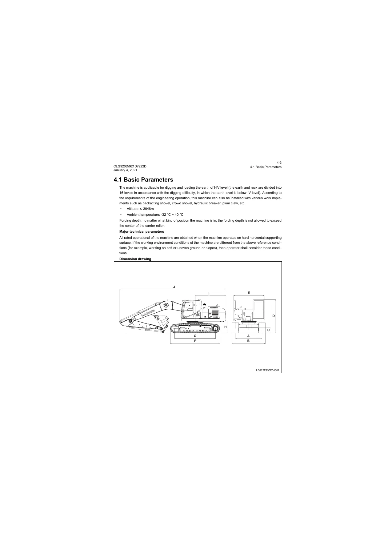
The machines are specified for digging and loading earth of I–IV level, optional implements such as backacting shovel, crowd shovel, hydraulic breaker and plum claw, altitude ≤ 3048 m, and ambient temperature −32 °C to 40 °C. Fording depth must not exceed the center of the carrier roller. Working-range figures for CLG922D versus CLG921Di include maximum digging height 9540 mm / 9369 mm, maximum digging depth 6615 mm / 5875 mm, maximum digging radius 9850 mm / 9435 mm, and ISO bucket digging force 159 kN on both listed configurations.

Complete PDF Bookmark Tree

Complete Bookmarks

The complete bookmarks in the “LiuGong CLG920D 921Di 922D Hydraulic Excavator Service Manual January 2021” are as follows:

Contentsp. 3
1 Safetyp. 5
The meaning of the safety warning symbol is as follows:p. 7
Article 65 of California Suggestionsp. 7
1.1 Safety Precautionsp. 8
Compressed Airp. 10
High-Pressure Solutionp. 11
Safe Disposal of Waste Liquidp. 12
Precautions for Accumulator Applicationp. 12
Asbestosp. 13
Prevention of Extruding Or Cutting-Offp. 13
Prevention of Burnsp. 14
Coolantp. 14
Oilp. 15
Batteryp. 15
Protection for Fire and Explosionp. 16
Diethyl Etherp. 17
Piping, Pipe and Hosep. 17
If following problems occur, it shall be replaced:p. 17
Fire Extinguisher and First-Aid Kitp. 18
Prevention of Injury by Thunderp. 18
Cab Protectorp. 19
Top and Front Guardsp. 19
Measures in Emergencyp. 19
Inner Space of Cabp. 19
Precautions for Accessoriesp. 20
1.2 Precautions for Lifting and Matching Operationsp. 21
Precautions for Operating Mobile Cranep. 22
Precautions for Operating Bridge Cranep. 22
Selection of Ropep. 23
2 Forewordp. 25
2.1 How to read the Manualp. 27
Composition of service manualp. 27
(1) Technical guidep. 27
(2) Workshop guidep. 27
Other reference manualsp. 27
For basic information of structure, operation and maintenance of the machine, refer to the following three manuals, which are distributed to the users in the form of spare parts.p. 27
User's Guidancep. 27
2.2 Marking of Revised Versionp. 28
2.3 General Torque Specificationsp. 29
Tightening torque of 24° cone O-ring sealed connectorp. 30
Tightening torque of flange-type sealed connector boltp. 31
Tightening torque of thread angle type sealed connectorp. 32
Joint tightening torquep. 32
2.4 Unit conversion tablep. 33
2.5 Cable Identification Methodsp. 34
Wire No.p. 34
Wire categoriesp. 35
Color abbreviation codesp. 35
Wire specificationsp. 36
Circuit type and color abbreviation codep. 36
2.6 Coating materialsp. 37
2.7 Weight tablep. 38
2.8 Usage specifications for oilsp. 39
3 Structural Function and Maintenancep. 41
3.1 Power Systemp. 43
3.1.1 Diesel Engine Related Partsp. 43
3.1.2 Water Radiator, Hydraulic Oil Cooler, Intercooler and Fuel Coolerp. 43
3.2 Undercarriage Systemp. 45
3.2.1 Track Frame and Tensionerp. 45
3.2.2 Idlerp. 46
3.2.3 Carrier Rollerp. 48
3.2.4 Track Rollerp. 50
3.2.5 Sprocketp. 52
3.2.6 Trackp. 53
3.3 Hydraulic Systemp. 54
3.3.1 Layout of Hydraulic Devicep. 54
3.3.2 Hydraulic Elementsp. 56
3.3.2.1 Main Pump Assemblyp. 56
Structure and function of main pump assemblyp. 56
Structure of main pump assembly:p. 56
(1) Main pump (pumps P1 and P2)p. 57
Structure and working principle of main pumpp. 57
Parts list of main pumpp. 59
Structure of adjusterp. 62
Principle of adjusterp. 63
(1) Flow controlp. 63
(2) Power controlp. 64
(3) Priority mechanism of small tilt (small flow) commandp. 65
(4) Power switching control (power decrease control)p. 65
Adjustment by adjusterp. 66
(1) Adjustment of maximum flow (pump body side)p. 66
(2) Adjustment of minimum flow (pump body side)p. 66
(3) Adjustment of input powerp. 66
(4) Adjustment of flow control characteristicsp. 67
Cause and handling of adjuster faultp. 68
Main pump maintenance referencesp. 69
Principle of pilot pumpp. 74
Diagram of pilot pump hydraulic circuitp. 74
Working principlep. 74
3.3.2.2 Main Control Valvep. 74
Specificationsp. 74
External viewp. 75
The interfaces of the main control valve are as followsp. 81
Structure diagramp. 83
Parts list of main control valvep. 93
Main control valve hydraulic circuitp. 94
Working principlep. 95
(3) Bucket armp. 98
(4) Boomp. 103
(5) Bucketp. 107
Maintenance referencesp. 127
3.3.2.3 Center Connectorp. 129
Parts Listp. 131
Working principlep. 131
Fault analysisp. 132
3.3.2.4 Explosion-Proof Valvep. 133
3.3.2.5 Hand Pilot Valvep. 135
Specificationsp. 135
Structurep. 135
Working principlep. 135
Maintenance referencesp. 137
3.3.2.6 Foot Pilot Valvep. 138
Specificationsp. 138
Structurep. 138
Working principlep. 139
Fault causes and countermeasuresp. 141
3.3.2.7 Cushion Valvep. 142
Exterior drawingp. 142
Structurep. 143
Schematic diagramp. 144
Working principlep. 145
Oil replacementp. 145
The specific working process is as follows:p. 145
Buffering functionp. 145
3.3.2.9 Travel Motor & Reduction Gearp. 146
Basic Structure and Schematic Diagramp. 147
Reduction gearp. 152
Hydraulic motor (brake valve)p. 153
Faults and Actions:p. 159
3.3.2.10 Swing Motor & Reduction Gearp. 161
Maintenance references of swing motorp. 166
Part replacement standardp. 166
Maintenance references of reduction gearp. 169
3.3.2.11 Cylinderp. 175
Basic functionsp. 175
Working principlep. 176
Cushioning process:p. 176
Arm cylinder cushioning:p. 177
Precautions on loading and handlingp. 177
Precautions for usep. 177
Periodic maintenancep. 178
3.3.2.12 Hydraulic Tank Assemblyp. 179
Structurep. 179
Working principlep. 182
3.3.3 Hydraulic Working Principlep. 184
3.3.3.1 Main Hydraulic Circuitp. 184
Leakage passagep. 187
3.3.3.2 Pilot Circuitp. 189
3.3.3.3 Negative Flow Control Circuit (With Control Spool in Neutral)p. 190
Negative flow control system (neutral)p. 190
3.3.3.4 Negative Flow Control Circuit (With Control Spool Moving)p. 192
3.3.3.5 Boom Lift Circuitp. 194
3.3.3.6 Boom Down Circuitp. 196
3.3.3.7 Arm Out Circuitp. 198
Arm Outp. 198
3.3.3.8 Arm In Circuit (Regenerative)p. 200
3.3.3.9 Arm In Circuit (Non-Regenerative)p. 202
3.3.3.10 Bucket In Circuitp. 204
3.3.3.11 Bucket Out Circuitp. 206
3.3.3.12 Left Swing Circuitp. 208
3.3.3.13 Swing Priority Circuitp. 210
3.3.3.14 Right Swing Circuitp. 212
3.3.3.15 Travel Forward (Fast)p. 214
3.3.3.16 Backward Travel (Slow)p. 218
3.3.3.17 Circuit for Bilateral Travel and Boom Liftp. 222
3.4 Work Implementp. 224
3.4.1 Maintenance References of Main Componentsp. 224
3.4.2 Maintenance References of Bucket Partp. 227
3.4.3 Maintenance References of Bucket Partp. 229
3.5 A/C Systemp. 231
3.5.1 A/C Pipeline Arrangementp. 231
3.6 Electrical Systemp. 233
3.6.1 Engine Controlp. 233
1) Start the enginep. 234
2) Engine speed controlp. 234
3) Stop the enginep. 234
3.6.2 Display Systemp. 235
Display for CLG920D/922D modelp. 235
(1) Instrument appearance and display for CLG920D/922D Modelp. 235
(2) Technical parametersp. 235
(3) Instrument interface for CLG920D/922D Modelp. 235
(4) Instrument menu for CLG920D/922D Modelp. 237
(5) ISystem settings for CLG920D/922D Modelp. 238
(6) System settingsp. 239
(7) Information for usep. 253
(8) System statep. 255
(9) Information of maintenancep. 255
Display for 921Di Modelp. 256
3.6.3 Electrical Control Systemp. 269
3.6.3.1 CLG920D/922D Auto-Idling Functionp. 270
3.6.3.2 CLG920D/922D Instantaneous Boostp. 271
3.6.3.3 CLG920D/922D Travel Speed Controlp. 272
3.6.3.4 CLG921Di Travel Two-Speed Circuitp. 1
3.6.3.5 CLG921Di Starting Circuitp. 1
3.6.3.6 CLG921Di Charging Circuitp. 1
3.6.3.7 CLG921Di Wiper Working Circuitp. 1
4 Parametersp. 279
4.1 Basic Parametersp. 281
4.2 Performance Parameters of Diesel Enginep. 288
4.3 Performance Parameters of Complete Machinep. 289
5 Testing and Adjustingp. 291
5.1 Performance test of complete machinep. 293
5.1.1 Diesel Engine Speedp. 294
5.1.2 Travel Speed (Idling Speed)p. 294
5.1.3 Driving Speed (Measured Speed)p. 295
5.1.4 Travel Deviationp. 296
5.1.5 Slewing service brake anglep. 298
5.1.6 Slewing Speedp. 299
5.1.7 Slewing Bearing Clearancep. 300
5.1.8 Action Time of Cylinderp. 302
5.1.9 Cylinder Settlementp. 305
5.1.10 Operating Force of Control Leverp. 306
5.1.11 Control Lever Strokep. 307
5.1.12 Boom Lifting and Slewing Actionp. 307
5.1.13 Pilot Pressurep. 308
5.1.14 Secondary Pilot Pressurep. 309
5.1.15 Output Pressure of Solenoid Proportional Valvep. 311
5.1.16 Setting Pressure of Main Relief Valvep. 312
5.2 Other Testsp. 320
5.2.1 Adjustment of Valve Clearancep. 320
Preparation Stepsp. 320
Adjustmentp. 323
Last proceduresp. 325
5.2.2 Measurement of Blow-by of Crankcasep. 328
Overviewp. 328
The general purpose of blow-by measurement lies in:p. 328
If so, the following measures shall be taken:p. 329
Measurement Toolsp. 329
For example:p. 329
Initial Inspectionp. 331
Measurementp. 332
5.2.3 Measurement of Engine Oil Pressurep. 335
Plug Torque Valuep. 337
5.2.4 Measurement and Adjustment of Track Tensionp. 338
Measurement of the Track Tensionp. 338
Machine state and parking sitep. 338
Measurement of the track tensionp. 338
Adjustment of Track Tensionp. 339
5.2.5 Inspection and Adjustment of Minus Feedback Pressure N1p. 340
Checkp. 340
Adjustmentp. 341
5.2.6 Inspection and Adjustment of Minus Feedback Pressure N2p. 341
5.2.7 Release of Remaining Pressure in Hydraulic oil Linesp. 342
5.2.8 Exhaust of Various Devicesp. 344
Exhaust the Air in the Pumpp. 345
Exhaust the Air in the Cylinderp. 345
Exhaust the Air in the Travel Motorp. 346
Exhaust the Air in the Accessories (if any)p. 347
5.2.9 Inspection of Diodep. 347
5.2.10 Adjustment of Compressor Belt Tensionerp. 348
Inspectionp. 348
Adjustmentp. 348
5.2.11 Performance Test of Travel Motors and Reduction Gearsp. 350
6 Fault Diagnosisp. 353
6.1 Precautions for Fault Diagnosisp. 355
6.2 Basic Fault Detection Before Maintenancep. 356
6.3 Classification of Faultsp. 358
6.4 Fault Diagnosis of Electrical Systemp. 360
6.4.1 E1 Troubleshooting Solution for Battery Power lossp. 360
6.4.2 E2 Troubleshooting Solution for Abnormal Batteryp. 362
6.4.3 E3 Automatic Idle Speed Is Abnormalp. 365
6.4.4 E4 Engine Cannot Be Startedp. 369
6.4.5 E5 Engine Flame-Out During Operationp. 377
6.4.6 E6 Engine Cannot Be Shut Downp. 382
6.4.7 E7 Preheater Does Not Workp. 386
6.4.8 E8 All Work Implements, Swing Mechanism and Travel System Cannot Movep. 391
6.4.9 E9 Display Panel Showing Nothingp. 396
6.4.10 E10 Incorrectly Displayed Hydraulic Oil Temperaturep. 400
6.4.11 E11 Fuel Gauge Unable Display Correct Valuep. 404
6.4.12 E12 Wiper Does Not Workp. 409
6.4.13 E17 Travel Alarm Unable To Soundp. 413
6.4.14 E14 A/C Panel Unable To Display.p. 417
6.4.15 E15 A/C No Air Or Abnormal Air Volumep. 426
6.4.16 E16 Poor A/C Refrigerationp. 430
6.4.17 E17 A/C Abnormal Alarm E11 – Inner Air Sensor Line Brokenp. 435
6.4.18 E18 A/C Abnormal Alarm E12 – Inner Sensor Short-Circuitedp. 437
6.4.19 E19 A/C Abnormal alarm E15 – Water Temperature Sensor Line Brokenp. 439
6.4.20 E20 A/C Abnormal Alarm E16 – Water Temperature Sensor Short-Circuitedp. 441
6.4.21 E21 A/C Abnormal Alarm E18 – Insolation Sensor Short-Circuitedp. 443
6.4.22 E22 A/C Abnormal Alarm E43 – Abnormal Air Outletp. 445
6.4.23 E23 A/C Abnormal Alarm E44 – Abnormal Blend Air Doorp. 447
6.5 Fault Diagnosis of Hydraulic System and Mechanical Systemp. 449
6.5.1 System Table of Hydraulic System and Mechanical Systemp. 449
6.5.2 H1 Excessive Braking Angle for Swing Stopp. 449
6.5.3 H2 Abnormal Noise From Pump Mounting Positionp. 450
6.5.4 H3 No Response After Engine Startp. 451
6.5.5 H4 Hydraulic Oil Emulsificationp. 452
6.5.6 H5 Abnormal Hydraulic Oil Temperature Risep. 453
6.5.7 H6 Swing Abnormally To Left and Right Directionsp. 454
6.5.8 H7 No Response for Single-Direction Swingp. 455
6.5.9 H8 Rotation Unable To Stopp. 456
6.5.10 H9 Failure To Actuate Unilateral Travel Mechanismp. 457
6.5.11 H10 Travel Deflectionp. 458
6.5.12 H11 Slow Speed of Boom, Arm or Bucketp. 459
6.5.13 H12 Weak Actions of Boom, Arm or Bucketp. 460
6.5.14 H13 Significantly Reduced Engine Speed or Engine Stallingp. 461
7 Removal and Installationp. 462
7.1 Overviewp. 464
7.2 Power Systemp. 466
7.2.1 Removal and Installation of Diesel Engine Assemblyp. 466
7.2.2 Removal and Installation of Radiator Assemblyp. 477
7.2.3 Removal and Installation of the Hydraulic Oil Radiatorp. 482
7.2.4 Removal and Installation of the Intercoolerp. 485
7.2.4 Removal and Installation of the Water Radiatorp. 488
7.3 Track Travel Systemp. 490
7.3.1 Removal and Installation of the Track Rollerp. 490
7.3.2 Removal and Installation of the Carrier Rollerp. 492
7.3.3 Removal and Installation of the Track Assemblyp. 494
7.3.4 Removal and installation of the Sprocketp. 496
7.3.5 Removal and Installation of the Idler Assembly and Tensioner Assemblyp. 497
7.3.6 Removal and Installation of the Revolving Framep. 499
7.3.7 Removal and installation of the Slewing Bearingp. 502
7.4 Covering Partsp. 504
7.4.1 Removal and Installation of the Engine Hoodp. 504
7.4.2 Removal and Installation of the Counterweightp. 507
7.5 Hydraulic Systemp. 509
7.5.1 Removal and Installation of Center Joint Assemblyp. 509
7.5.2 Disassembly and Assembly of the Center Jointp. 512
7.5.3 Removal and Installation of Hydraulic Tankp. 516
7.5.4 Removal and Installation of the Main Control Valve Assemblyp. 521
7.5.5 Disassembly and Assembly of the Main Control Valvep. 525
7.5.6 Removal and Installation of Main Pump Assemblyp. 540
7.5.7 Removal and Installation of Main Pump Assemblyp. 544
7.5.8 Removal and Installation of the Travel Pilot Valve Assemblyp. 560
7.5.9 Disassembly and Assembly of Travel Pilot Valvep. 563
7.5.10 Removal and Installation of Hand Pilot Valve Assemblyp. 588
7.5.11 Disassembly and Assembly of the Hand Pilot Valve Assy.p. 591
7.5.12 Removal and Installation of the Travel Motor & Speed Reducerp. 609
7.5.13 Disassembly and Assembly of Travel Motor & Speed Reducer Assemblyp. 614
Part list of slewing motor & speed reducerp. 617
The following operation is carried out without replacement.p. 649
If the following part is to be replaced,p. 652
If no component is required to be replaced, carry out the following operation directly.p. 652
[A] Adjustment of ball bearingp. 662
Tool(s):p. 662
[B] Adjust the axial clearance of cone bearing.p. 663
Tool(s):p. 664
7.5.14 Removal and Installation of Slewing Motor & Speed Reducerp. 665
7.5.15 Disassembly and Assembly of Slewing Motor & Speed Reducerp. 669
7.6 Work Implementp. 695
7.6.1 Removal and Installation of Bucketp. 695
Installation steps:p. 697
7.6.2 Removal and Installation of Link and Leverp. 698
7.6.3 Removal and Installation of Armp. 701
7.6.4 Removal and Installation of Boomp. 703
7.6.5 Removal and Installation of Work Implement Assemblyp. 708
7.6.6 Removal and Installation of Bucket Cylinder Assemblyp. 712
7.6.7 Removal and Installation of Arm Cylinder Assemblyp. 715
7.6.8 Removal and Installation of Boom Cylinder Assemblyp. 718
7.6.9 Disassembly and Assembly of Cylinderp. 722
Preparationsp. 723
7.7 A/C Systemp. 732
7.7.1 Removal and Installation of A/C Compressor Assemblyp. 732
7.7.2 Removal and Installation of A/C Evaporator Assemblyp. 737
7.8 Cabp. 746
7.8.1 Removal and Installation of Cabp. 746
7.8.2 Removal and Installation of Floor Frame Assemblyp. 751
8 Attached Drawingp. 1
8.1 Hydraulic Schematic Diagramp. 1
8.2 Electrical Schematic Diagramp. 1
8.2.1 CLG920D/922D Electrical Schematic Diagramp. 1
8.2.2 CLG921Di Electrical Schematic Diagramp. 1
8.3 A/C Schematic Diagramp. 1
8.3.1 CLG920D/922D A/C Schematic Diagramp. 1
8.3.2 CLG921Di A/C Electrical Schematic Diagramp. 1

Chapters Covered

  • 1 Safety — safety precautions; compressed air; high-pressure fluid; waste liquid; accumulator; asbestos; crush and cut hazards; burns; coolant and oil; battery; fire and explosion; diethyl ether; piping and hose; fire extinguisher and first-aid; thunder; cab protector; accessories; lifting and matching operations; rope selection
  • 2 Foreword — how to read the manual; revision marking; general torque specifications; unit conversion; cable identification; coating materials; component weight table; oil usage specifications
  • 3 Structural Function and Maintenance — power system (engine related parts; water radiator, hydraulic oil cooler, intercooler and fuel cooler); undercarriage (track frame and tensioner, idler, carrier roller, track roller, sprocket, track); hydraulic system (device layout; main pump; main control valve; center connector; explosion-proof valve; hand and foot pilot valves; cushion valve; travel motor and reduction gear; swing motor and reduction gear; cylinders; hydraulic tank); hydraulic working principle (main circuit, pilot circuit, negative flow control, boom / arm / bucket / swing / travel circuits); work implement maintenance references; A/C pipeline arrangement; electrical system (engine control, display system, auto-idling, instantaneous boost, travel speed control, CLG921Di starting / charging / wiper circuits)
  • 4 Parameters — basic machine parameters and dimension drawings; diesel engine performance; complete-machine performance standards
  • 5 Testing and Adjusting — complete-machine performance tests (engine speed, travel and driving speed, travel deviation, slewing brake angle and speed, slewing bearing clearance, cylinder action time and settlement, control-lever force and stroke, boom lift and slew, pilot and secondary pilot pressure, solenoid proportional-valve output, main relief setting); other tests (valve clearance, crankcase blow-by, engine oil pressure, track tension, minus-feedback pressures N1 and N2, residual hydraulic pressure release, air exhaust of pump / cylinder / travel motor / attachments, diode check, compressor belt tension, travel motor and reduction-gear performance)
  • 6 Fault Diagnosis — precautions and basic checks; electrical faults E1–E23 (battery, auto-idle, start and shutdown, preheater, no implement / swing / travel movement, display, hydraulic-oil temperature display, fuel gauge, wiper, travel alarm, A/C panel and sensors); hydraulic and mechanical faults H1–H13 (swing brake angle, pump noise, no response after start, emulsified oil, oil overheat, swing and travel faults, weak or slow boom / arm / bucket, engine speed drop or stall)
  • 7 Removal and Installation — power system (engine, radiator, hydraulic oil radiator, intercooler, water radiator); track travel system (rollers, track, sprocket, idler and tensioner, revolving frame, slewing bearing); covering parts (hood, counterweight); hydraulic system (center joint, tank, main control valve, main pump, travel and hand pilot valves, travel motor and reducer, slewing motor and reducer, including disassembly of several assemblies); work implement (bucket, link and lever, arm, boom, complete implement, boom / arm / bucket cylinders and cylinder overhaul); A/C compressor and evaporator; cab and floor frame
  • 8 Attached drawing — hydraulic schematic; CLG920D / CLG922D and CLG921Di electrical schematics; CLG920D / CLG922D A/C schematic and CLG921Di A/C electrical schematic

Taken together, the LiuGong CLG920D 921Di 922D Hydraulic Excavator Service Manual January 2021 is both a systems textbook and a shop teardown book. Chapter 3 explains how the dual axial-piston pumps, 3.9 MPa pilot circuit, negative-flow control, swing-priority and travel circuits actually move oil. Chapter 4 and the test chapter then give the numbers a technician measures against. Chapter 6 turns those same systems into coded electrical trees and hydraulic symptom charts. Chapter 7 is the long workshop section: lift points, residual-pressure release, labeled hose disconnects, torque call-outs and reassembly notes for nearly every major assembly on the machine. Chapter 8 supplies the full-page hydraulic, electrical and A/C drawings needed when tracing a circuit on the machine.

Hydraulic, Electrical and Service Data You Will Use on the Machine

The hydraulic system is described as a double-block axial variable plunger main pump with maximum system flow 2 × 210 L/min. Main relief set pressure is 31.8 MPa, rising to 33.3 MPa during instantaneous supercharging. Boom, arm and bucket outlet safety valves are listed at 37.2 MPa. Slewing-motor relief is 25.5 MPa and travel-motor relief 31.8 MPa. Pilot circuit pressure is 3.9 MPa from a gear-type pilot pump. Boom, arm and bucket cylinders are printed as 2-φ120 × φ85 × 1187 mm (quantity–bore × rod × stroke). Standard boom length is 5680 mm; standard arm is 2910 mm on CLG920D / CLG922D and 2400 mm on CLG921Di.

Electrical architecture is 24 V with two 12 V batteries. The display chapter covers coolant temperature, fuel level, system voltage, engine oil pressure and hydraulic oil temperature indications, plus alarm colors and menu functions. Model-specific control notes include auto-idling and instantaneous boost on CLG920D / CLG922D, two-speed travel on CLG921Di, and separate starting, charging and wiper circuits for CLG921Di. A/C data includes 5000 W refrigerating capacity, 5800 W heating capacity, R134a charge 950 ± 50 g, Denso 10S15C compressor and ND-OIL8 oil.

Oil and interval tables for the QSB7 machine list engine oil 24 L at 500 hours, swing reduction gear 3.4 L at 1000 hours, travel reduction gears 5.5 L × 2 at 1000 hours, hydraulic tank 210 L / system 330 L at 2000 hours, fuel tank 420 L, and cooling system 25 L at 2000 hours. Recommended grades include 15W-40 (API CI-4) engine oil as the factory-fill mark, SAE 85W-140 (API GL-4) for swing reduction, SAE 80W-90 (API GL-4) for travel reduction, and ISO VG 46 hydraulic oil as the marked factory fill, with VG 32 and VG 68 mapped to ambient ranges. Fastener torque tables cover engine mounts, pump, main valve, swing and travel reducers, track shoes (M20-12.9 at 750 N·m), counterweight (M30-10.9 at 1850 N·m), plus 24° cone O-ring fittings and flange connector bolts. A component weight table supports crane selection: engine assemblies 432–496 kg, revolving frame 1882 kg, counterweight 4300 kg (4000 kg is also given for CLG921Di in the R&I chapter), boom 1616 kg, track frame 2711 kg, and so on.

IMAGES PREVIEW

LiuGong CLG920D 921Di 922D Hydraulic Excavator Service Manual January 2021 — PDF page 1 preview
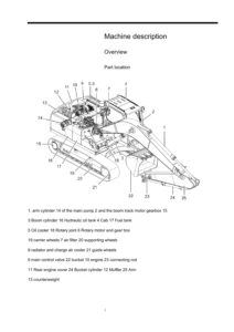
LiuGong CLG920D 921Di 922D Hydraulic Excavator Service Manual January 2021 — PDF page 281 preview
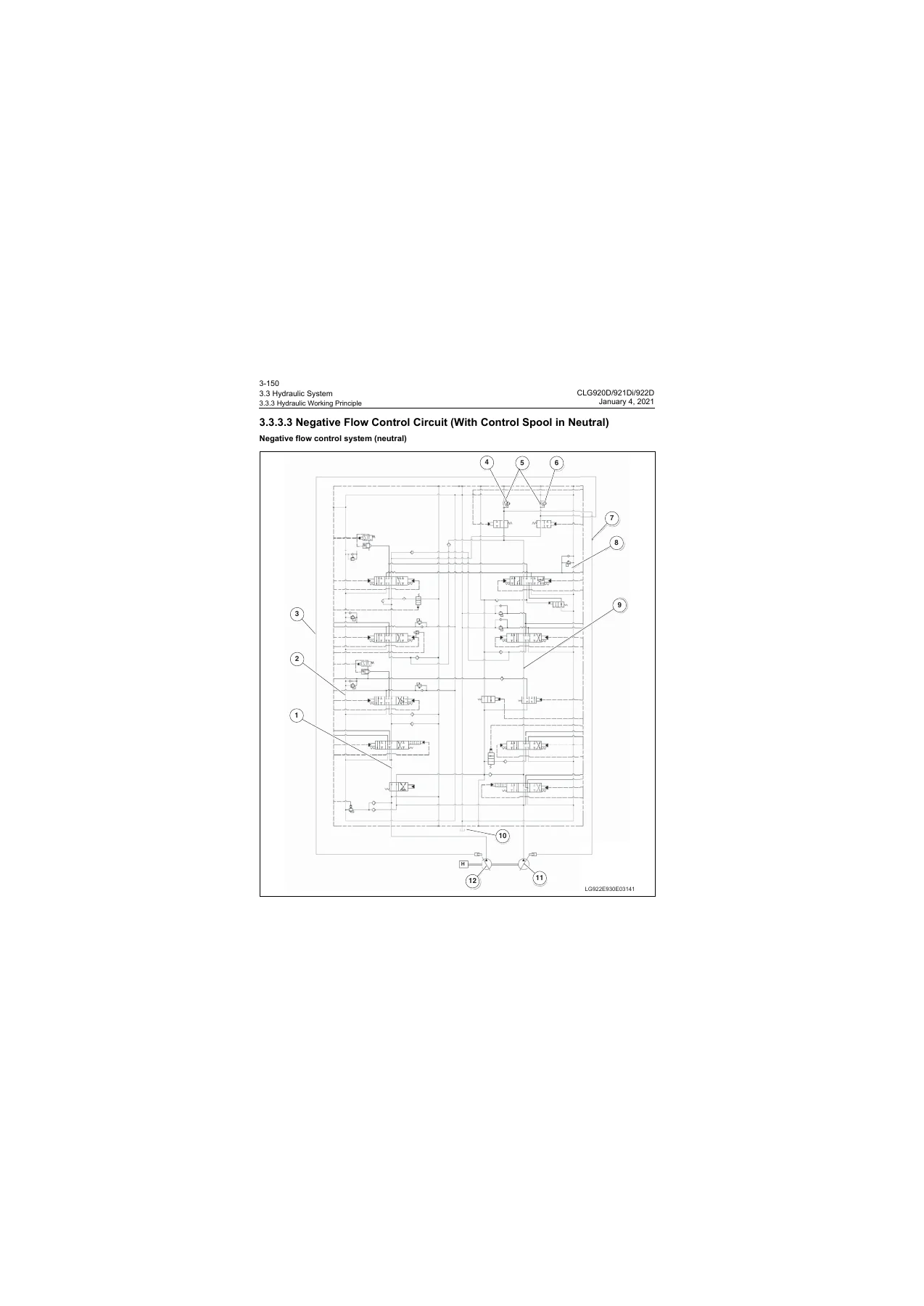
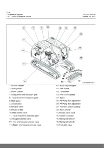
LiuGong CLG920D 921Di 922D Hydraulic Excavator Service Manual January 2021 — PDF page 190 preview

Testing, Diagnosis and Shop Teardown

Performance standards in section 4.3 and the matching procedures in chapter 5 tell the technician how to set hydraulic oil temperature (typically 45–55 °C or 50 ± 5 °C), park the machine, and measure idle speeds, 20 m travel times, 3-revolution track and swing times, travel deflection, cylinder cycle times, 10-minute cylinder settlement, lever forces and strokes, combined boom-lift-and-slew, pilot pressure 3.9–4.1 MPa at high idle, main relief 33.3–34.3 MPa, port-relief values around 35.3–37 MPa, and pump flow 210 × 2 L/min. Engine-side checks include valve-clearance adjustment, crankcase blow-by measurement, oil-pressure measurement, and compressor-belt tension. Hydraulic service steps cover N1 / N2 negative-flow feedback, residual-pressure release, and bleeding the pump, cylinders, travel motors and attachments.

Fault diagnosis is split into electrical codes E1 through E23 and hydraulic-mechanical symptoms H1 through H13. Electrical trees cover a dead battery, no-start, runaway idle, no shutdown, inoperative preheater, dead implements, blank cluster, wrong oil-temperature or fuel-gauge readings, silent travel alarm, and a full set of A/C sensor and servo faults. Hydraulic trees cover excessive swing-stop angle, pump-area noise, no response after start, emulsified oil, overheating oil, one-way or both-way swing faults, one-side travel, travel drift, slow or weak boom / arm / bucket, and sudden engine-speed collapse. Each path assumes the machine is parked level with implements grounded and residual pressure released before connectors or valves are opened.

Chapter 7 is the longest practical section. Power-system R&I includes engine, radiator pack, hydraulic oil cooler, intercooler and water radiator. Undercarriage work covers track rollers, carrier rollers, track groups, sprockets, idler and tensioner, revolving frame and slewing bearing (bearing weights 445 kg on CLG920D / CLG922D and 315 kg on CLG921Di). Hydraulic R&I goes from the center joint and tank through the main control valve and main pump, then into bench disassembly of the travel and hand pilot valves, travel motor/reducer and swing motor/reducer. Implement work covers bucket, link and lever, arm, boom, the complete front, and all three cylinder assemblies plus cylinder overhaul. Cab, floor frame and A/C compressor / evaporator complete the shop coverage. Warnings throughout require battery-negative disconnect, hydraulic-tank venting, slings sized from the weight table, and LiuGong replacement parts when a diagnosis tree calls for a sensor or valve change.

The foreword also points readers to the separate parts catalogue, the operator use-and-maintenance manual, and the Cummins engine parts manual for parts identification and daily operation. This service volume is the document used once the machine is in the bay for measurement, diagnosis or assembly replacement.

Get the Manual and Start Working

With the LiuGong CLG920D 921Di 922D Hydraulic Excavator Service Manual January 2021 on hand you can set main and port relief valves, bleed pumps and motors after a hose change, diagnose a blank monitor or a one-side travel complaint, and lift the engine, pump, main valve, swing bearing or front structure using the printed weights and torque values. Using the published pressures, cycle times and settlement limits keeps a 21–22 t excavator from being reassembled to the wrong spec. After payment you receive the PDF immediately — no shipping, readable on any device, and printable for the toolbox or the machine cab.
Reviews

There are no reviews yet.

Be the first to review “LiuGong CLG920D 921Di 922D Hydraulic Excavator Service Manual January 2021”

What Our Customers Say

★★★★★ Live reviews from customers
Loading customer reviews...
0
    0
    Your Cart
    Your cart is emptyReturn to Shop
    🛒
    Recently Purchased
    🕒 verified order