
LiuGong 9027FZTS and 9027FZTSG4 Hydraulic Excavator Service Manual
Original price was: $39.95.$24.95Current price is: $24.95.
Complete workshop service manual for LiuGong 9027FZTS and 9027FZTSG4 hydraulic excavators equipped with Yanmar 3TNV80F and Kubota D1105 engines. Delivers comprehensive factory technical data, hydraulic schematics, electrical circuit diagrams, operational principles, performance testing standards, and troubleshooting procedures.
Description
Complete Workshop Service Documentation for LiuGong Mini Excavators
The LiuGong 9027FZTS and 9027FZTSG4 Hydraulic Excavator Service Manual is an essential technical resource engineered specifically for heavy equipment mechanics, field technicians, and fleet maintenance specialists. Covering the compact 9027FZTS platform across global emissions configurations—including Tier 4 Final, EU Stage V, China State III, and China State IV variants—this manual provides comprehensive technical guidance to maintain, troubleshoot, test, and overhaul every primary machine assembly. Whether servicing a machine fitted with the Yanmar 3TNV80F naturally aspirated diesel or the Kubota D1105 powerplant, this manual offers the exact factory clearances, hydraulic pressure benchmarks, electrical circuit schematics, and tightening torques required for professional workshop repairs.
File Details
- Manual Type: Service Manual
- Brand / Manufacturer: LiuGong (柳工)
- Applicable Models: 9027FZTS, 9027FZTSG4
- Engine Configurations: Yanmar 3TNV80F-SNLY, Kubota D1105-E4B-LGM-1
- Document Publication Number: 202403002
- Publication Date: March 8, 2024
- Language: English
- Page Count: 646 pages
- File Format: Portable Document Format (PDF)
Chapters Covered
- 1 Safety
- Safety Precautions and General Workshop Rules
- Compressed Air and High-Pressure Fluid Hazards
- Safe Disposal of Waste Liquids and Environmental Protection
- Precautions for Hydraulic Accumulator Application
- Asbestos Safety and Prevention of Crushing or Cutting
- Burn Prevention, Hot Coolant, and Hydraulic Oil Handling
- Battery Maintenance and Fire/Explosion Prevention Guides
- Pipeline, High-Pressure Pipe, and Hydraulic Hose Integrity
- Fire Extinguisher, First-Aid Kit, and Thunder Protection
- Cab Protectors (Top Guard and Front Guard Requirements)
- Inner Space Dimensions (SAE J154 / ISO 3411) and Emergency Measures
- Collaborative Rigging, Crane Operations, and Wire Rope Cable Selection
- 2 Basics
- Manual Composition and Suggested Diagnostic Workflow
- Marking and Interpretation of Revision Numbers
- General Fastener Torque Specifications (Metric 8.8 and 10.9)
- 24-Degree Cone O-Ring Pipe Fitting and Flange Bolt Torques
- Thread Angle Sealing Pipe Fitting Tightening Values
- Cable Identification Methods, Wire Gauges, and Color Codes
- Specialty Coating Materials, Sealants, and Chemical Lockers
- Complete Machine Component Weight Table for Hoisting
- Specifications for Oil Application, Fluid Capacities, and Change Intervals
- 3 Structural Function and Maintenance
- Power System Mounting (Yanmar and Kubota Configurations)
- Cooling System, Water Radiator, and Hydraulic Oil Cooler Lines
- Undercarriage: Travel Frame, Recoil Springs, Track Tensioners, and Idlers
- Track Rollers, Carrier Rollers, Drive Sprockets, and Rubber/Steel Tracks
- Slewing Bearing Structural Parameters and Maintenance Clearances
- Hydraulic Device Overall Layout and Component Locations
- Axial Plunger Variable Main Pump: Structure, Flow Regulation, and LS Adjustment
- HVSE-09-10-P270-BE007 Closed-Center Load Sensing Main Control Valve
- Center Revolving Joint Internal Passages, Seals, and Failure Analysis
- Optional Boom and Arm Cylinder Explosion-Proof Safety Valves
- Hand Pilot Valves (4TH5, YDVH1) and Dual-Pedal Travel Pilot Valve (4TH5NR)
- Travel Motors: PHV-3B-35A and FTM02C-021011 Two-Speed Drives
- Swing Motors: PCR-2B-10A and FSM12A Planetary Reduction Drives
- Hydraulic Cylinders: Boom, Arm, Bucket, Dozer, and Swing Deflection
- Hydraulic Tank Filtration, Breather Valves, and Return Circuit Functions
- Circuit Schematics: Boom, Arm, Bucket, Swing, Travel, Dozer, and Quick-Coupler
- Auxiliary Attachment 1 (Hammer/Shear) and Attachment 2 (Clamp) Circuits
- Work Implement Pin-to-Bushing Tolerances and Maintenance Reference Limits
- Cab Air Conditioning (HVAC) and Heating System Piping
- Electrical Starting, Charging, Instrument Display Screen, and Monitoring Logic
- 4 Parameters
- Basic Machine Technical Parameters and Operating Envelopes
- Overall Dimensions and Shipping Specifications
- Component Engineering Specifications
- Yanmar 3TNV80F and Kubota D1105 Engine Performance Data
- Standard Machine Operational Speeds, Cycle Times, and Relief Pressures
- 5 Test and Adjustment
- Engine High and Low Idling Speed Verification
- Track Travel Speed (Idling and Measured 30m Ground Run)
- Travel Tracking Deviation Measurement
- Slewing Speed and Slewing Service Braking Angle Checks
- Dial Indicator Measurement of Slewing Bearing Vertical/Horizontal Play
- Hydraulic Cylinder Action Speeds and Settlement (Drift) Rates
- Control Lever Operating Force and Stroke Travel Tolerances
- Main Circuit and Port Relief Pressure Testing and Valve Shimming
- Pilot Pressure and Secondary Pilot Pressure Verification
- Track Sag Measurement and Hydraulic Tensioning Procedures
- Hydraulic Line Residual Pressure Release and System Air Bleeding
- Electrical Diode Testing and HVAC Refrigerant Evacuation and Recharging
- 6 Fault Diagnosis
- Systematic Troubleshooting Guides for Hydraulic, Mechanical, and Electrical Systems
- Fault Code Indexes, Diagnostic Flowcharts, and Corrective Actions
- 7 Removal and Installation
- Step-by-Step Disassembly and Assembly Instructions for Major Components
- 8 Attached Drawing
- Complete Electrical Schematic Diagrams and Hydraulic System Circuit Blueprints
Together, these eight detailed sections provide technicians with a standalone, factory-authorized diagnostic foundation. By walking directly from fault symptoms to component testing, hydraulic pressure adjustment, and physical removal/reinstallation, this manual eliminates guesswork during severe mechanical overhauls.
In-Depth Hydraulic and Powertrain Architecture
The LiuGong 9027FZTS service manual provides thorough mechanical insight into the closed-center load-sensing system (CLSS). Powered by a variable displacement axial piston pump delivering up to 86.4 L/min at 32 MPa, the hydraulic circuit operates via the specialized HVSE-09-10 ten-spool main control valve. This document clearly diagrams how the load-sensing (LS) differential pressure valve balances compound excavator actions—such as simultaneous boom lift and arm curling—by dynamically matching pump swashplate angle to highest actuator load pressure. Technicians will find explicit bench and on-machine procedures to adjust the LS differential setting screw (23.4 degrees per 0.1 MPa) and tune main pump power output within plus or minus 2.5 N·m.
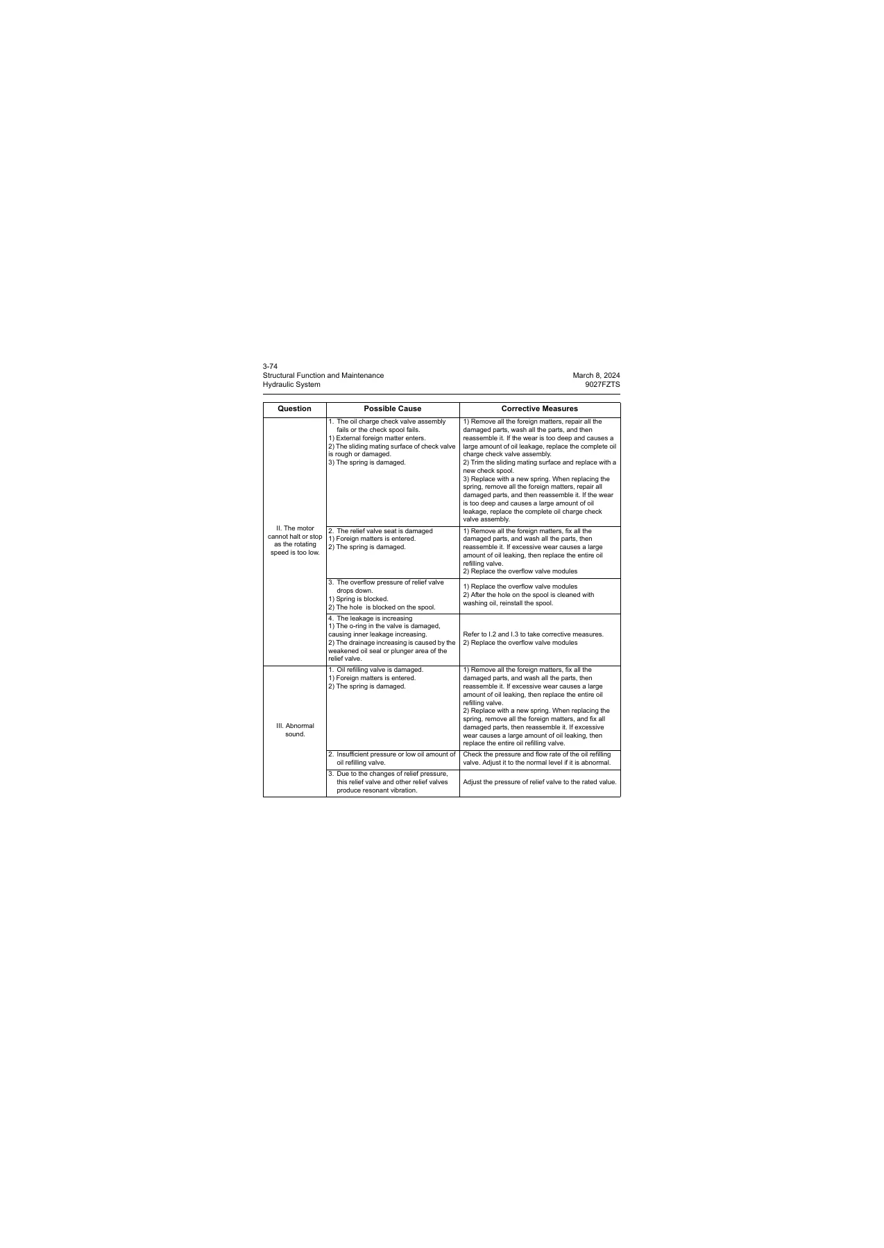
Detailed cutaway drawings explain the internal working cycles of both the PHV-3B-35A and FTM02C travel motors, including the dual-speed variable displacement swashplate controls, counterbalance valves, automatic kick-down mechanisms, and spring-applied, hydraulically released multi-disc parking brakes. In addition, slewing drive diagnostics cover both the PCR-2B-10A and FSM12A motor configurations, guiding technicians through relief valve pressure shimming (18.6 MPa), anti-reversing valve troubleshooting, and planetary gear reducer lubrication management.
Electrical Controls, LCD Instrument Panel, and Diagnostics
Troubleshooting electrical circuits on the 9027FZTS is made straightforward with factory wiring identification codes, wire categories (AEX, AV, AVS, AVSS, QVR), and harness routing schematics. The manual details the operational logic of the 34-pin multi-function LCD monitor, including input/output pin definitions, CAN-bus communication channels, auto-idle control delay timers (5-second drop to low idle), and automatic preheating circuits. Technicians can reference the full index of maintenance reminder intervals (b-001 through b-020), anti-theft GPS lock statuses (gps-01, gps-02, gps-03), and terminal voltage checks across the engine oil pressure switch, coolant temperature sensor, fuel level sender, and secondary emergency stop circuits.
Undercarriage Wear Limits and Mechanical Overhaul Standards
Every structural wear component on the 9027FZTS undercarriage is documented with original factory dimensions, machining tolerances, and replacement discard thresholds. Mechanics can reference precise service limits for:
- Track Tensioner: Free spring length (190 mm), installation length (160 mm at 2000 kN load), and replacement limit (145 mm at 3000 kN).
- Front Idler: Guide plate vertical width (88 mm standard, 90 mm max limit) and horizontal width (161 mm standard, 163 mm max limit); bushing-to-shaft standard clearance (0.15 to 0.24 mm).
- Track Rollers: Flange outer diameter (114 mm standard, 110 mm wear limit) and tread diameter (85 mm standard, 81 mm wear limit).
- Drive Sprocket: Tooth width (23.7 mm standard, 19.7 mm wear limit) and radial tooth wear limit (2.0 mm).
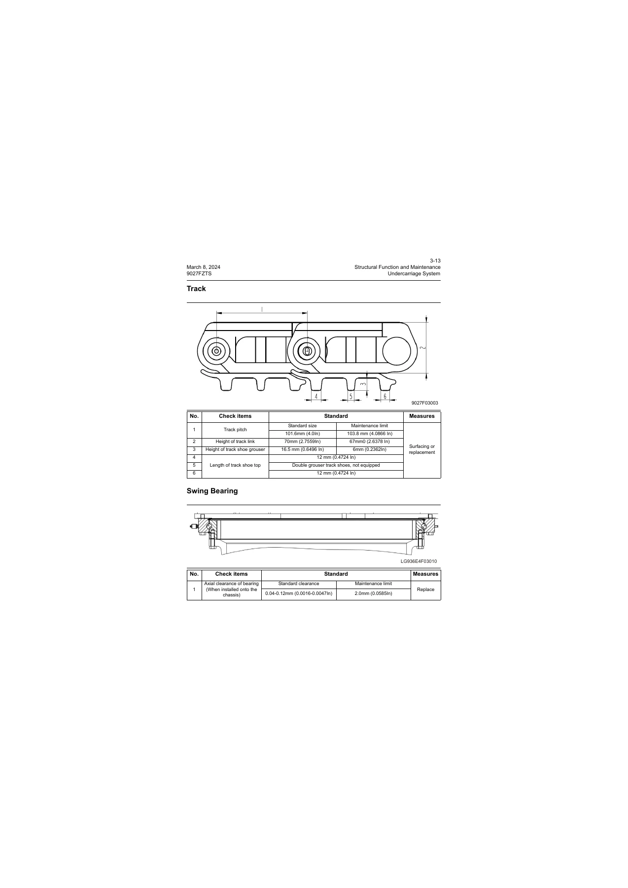
- Steel and Rubber Tracks: Track pitch (101.6 mm standard, 103.8 mm discard limit) and grouser height (16.5 mm standard, 6.0 mm limit).
- Work Implement Pins: Detailed pin-to-bushing allowable play (up to 1.0 mm maximum permissible clearance) across boom base, boom-to-arm, arm-to-bucket, rocker links, and swing bracket pivot points.
Performance Testing and Hydraulic Line Relief Adjustments
To verify machine condition following major repairs, the LiuGong 9027FZTS excavator workshop manual outlines step-by-step performance testing methods. It provides exact benchmarks for travel deviation (less than or equal to 600 mm over 20 m), 3-revolution track spin times (rabbit vs. tortoise modes), clockwise/counterclockwise swing speeds (19 plus or minus 1.5 seconds per 3 revolutions), and swing service brake drift angles (less than or equal to 25 degrees). Cylinder stroke speed tables and hydraulic internal leakage settlement ratings (less than or equal to 10 mm drift over 10 minutes) ensure that boom, arm, and bucket assemblies hold load to factory standards. Technicians are provided with port-by-port gauge hookup instructions to set the main system relief valve (21.6 MPa), port overload relief valves (up to 30 MPa on arm retraction), and pilot source reducing valve (3.4 to 3.7 MPa).
Professional Repair Capability and Instant Delivery
Acquiring this 9027FZTS hydraulic excavator repair manual empowers shop mechanics, mobile field technicians, and owner-operators to execute comprehensive servicing with total mechanical certainty. Utilizing precise factory specifications safeguards hydraulic pumps from premature cavitation, prevents structural failure from incorrect fastener torque, and ensures electronic sensors remain properly calibrated. Delivered as an instant high-resolution digital PDF download, this manual is immediately accessible on desktop computers, workshop laptops, rugged tablets, or smartphones without shipping delays. Fully formatted for high-definition viewing and clean workshop printing, you can print dedicated troubleshooting schematics or whole chapters directly for the job site.



Reviews
There are no reviews yet.