
Komatsu PC800-8, PC800SE-8, PC800LC-8, PC850-8, PC850SE-8 Excavator Shop Manual
Original price was: $49.95.$29.95Current price is: $29.95.
Comprehensive workshop service manual for Komatsu PC800-8, PC800SE-8, PC800LC-8, PC850-8, and PC850SE-8 hydraulic excavators powered by the SAA6D140E-5 engine. Covers technical specifications, electronic OLSS hydraulics, structural maintenance standards, testing and adjusting, failure codes, and full disassembly and assembly procedures.
Description
Komatsu PC800-8, PC800SE-8, PC800LC-8, PC850-8, PC850SE-8 Excavator Shop Manual
The Komatsu PC800-8, PC800SE-8, PC800LC-8, PC850-8, PC850SE-8 Excavator Shop Manual (Form No. SEN00373-06) is the definitive, factory-level technical reference engineered for workshop mechanics, heavy equipment technicians, and fleet maintenance teams. Spanning comprehensive engineering systems across all five production variants, this publication delivers complete service guidance for machines powered by the Tier 3 Komatsu SAA6D140E-5 diesel engine. From full-scale hydraulic circuit diagnostics and electronic OLSS calibration to structural wear limits and complete powertrain overhaul, this manual provides exact manufacturer data required to maintain heavy mining and mass-excavation machinery at peak operating capability.
File Details
- Manual Type: Shop Manual / Workshop Service Repair Manual
- Brand: Komatsu
- Machine Models Covered: PC800-8, PC800SE-8, PC800LC-8, PC850-8, PC850SE-8 Hydraulic Excavators (Backhoe and Loading Shovel configurations)
- Engine Model: Komatsu SAA6D140E-5 (4-cycle, water-cooled, in-line, direct injection, turbocharged with air-to-air aftercooler)
- Applicable Serial Numbers: PC800-8 (Serial 50001 and up), PC800SE-8 (Serial 50001 and up), PC800LC-8 (Serial 50001 and up), PC850-8 (Serial 10001 and up), PC850SE-8 (Serial 10001 and up)
- Document Form Number: SEN00373-06 (Section Form Nos. SEN00374-06 through SEN01060-01, including SEN00784-02 and SEN00786-02)
- Language: English
- Page Count: 1117 pages
- File Format: Portable Document Format (PDF)
Chapters Covered
- 00 Index and Foreword: Composition of shop manual, table of contents, safety notices, general precautions, sling work and crane operation standards, handling of electronic mechatronics and hydraulic components, modern engine wire connector locking types, electric wire coding system, operational precautions, push-pull coupler connection/disconnection, standard tightening torque tables, and metric/imperial conversion charts.
- 01 Specification: General dimensional drawings (backhoe and loading shovel specifications), working range envelope schematics, technical data tables for PC800-8, PC800SE-8, PC800LC-8, PC850-8, and PC850SE-8, component weight breakdown tables, and comprehensive fluid, fuel, coolant, and lubricant specification charts.
- 10 Structure, Function and Maintenance Standard:
- Engine and Cooling System: Flywheel coupling construction, coupling forced-lubrication circuit, radiator core CF68-4, air-cooled hydraulic oil cooler CF42-1, aftercooler, and fuel cooler.
- Power Train: Overall powertrain drive schematic, swing machinery dual planetary reduction gearing, swing circle bearing structure, final drive triple planetary reduction mechanisms, and drive sprocket wear profiles.
- Undercarriage and Frame: Track frame architecture, hydraulic recoil spring assemblies, front idlers, carrier rollers, single and double flange track rollers, assembly-type triple grouser shoes, and heavy-duty double shoes.
- Hydraulic System (Part 1 & Part 2): Hydraulic piping schematics, reservoir tank and filtration circuits, dual variable-displacement main piston pumps (HPV375+375), swash plate control servo valves, electronic proportional control (EPC) valves, valve control (VC) spool operation, self-pressure reducing valves, variable fan drive pump (LPV90) and reversible fan motor (LMF110), motorized automatic grease pump, L.H. 5-spool control valve, R.H. 4-spool control valve, straight-travel valve, axial piston swing motors (KMF125AB-5), center swivel joint, variable displacement travel motors (MSF-340VP-EH11) with counterbalance braking, pilot PPC accumulators, work equipment and travel pilot valves, solenoid valve banks, quick return valves, and hydraulic cylinders.
- Work Equipment: Boom, arm, standard backhoe bucket, loading shovel bucket, and bottom dump cylinder linkages, bushing clearances, and structural pin dimensions.
- Cab and Attachments: Cab layout and air conditioner refrigerant piping.
- Electrical System: Engine electronic fuel governing, network communication, electric control architecture, machine monitor panel system, sensor operational profiles, and pump controller interface.
- 20 Standard Value Table: Standard service value tables for engine SAA6D140E-5 (compression, blow-by, boost pressure, exhaust temperature, oil pressures) and standard service value tables for chassis (hydraulic relief pressures, PPC pilot pressures, EPC currents, actuator operating cycle times, travel deviations, and internal component leakage limits).
- 30 Testing and Adjusting: Dedicated diagnostic tooling lists, engine RPM measurement, boost pressure testing, exhaust temperature recording, smoke opacity checking, engine valve clearance adjustment, compression testing, blow-by measurement, fuel rail pressure and return rate leak testing, air bleeding procedures, belt tensioning, hydraulic circuit pressure setting, pump control calibration, and electronic monitor service routines.
- 40 Troubleshooting: Troubleshooting logic, failure code matrices (CA engine fault codes, DA network communication errors, DW/DX solenoid circuit faults), electrical E-mode troubleshooting charts, hydraulic and mechanical H-mode fault trees, and engine S-mode symptom diagnoses.
- 50 Disassembly and Assembly: Special overhaul tools, critical torque sequences, removal and installation procedures for the SAA6D140E-5 engine, PTO coupling, main hydraulic pumps, cooling packs, swing drives, final drives, undercarriage tracks, control valves, hydraulic cylinders, and work equipment structures.
- 90 Diagrams and Drawings: Complete machine hydraulic circuit diagrams, electrical schematics, and cab/chassis wiring connector arrangement diagrams.
By compiling these comprehensive sections into a unified engineering guide, the Komatsu PC800-8, PC800SE-8, PC800LC-8, PC850-8, PC850SE-8 Excavator Shop Manual gives field service technicians and workshop rebuilders complete clarity on complex electro-hydraulic interactions, precise component wear limits, and step-by-step repair methodologies.
Structure, Function, and Advanced Hydraulic Systems
The hydraulic infrastructure of the Komatsu PC800-8 and PC850-8 series utilizes an advanced Open-Center Load Sensing System (OLSS) managed electronically by the machine pump controller. Main hydraulic power is delivered by the tandem HPV375+375 variable displacement axial piston pump capable of discharging 490 + 490 liters per minute at a rated main relief pressure of 31.4 MPa (320 kg/cm²). The manual details the mechanical and hydraulic interactions between the internal swash plate cradle, servo piston, and the electronic VC valve. When the controller delivers signal current to the pump EPC valve, pilot pressure shifts the VC sleeve against calibrated spring tension, venting or pressurizing the large-diameter chamber of the servo piston to alter pump swash plate angles instantly according to system load.
The manual provides thorough architectural coverage for both multi-spool main control valves: the Left-Hand 5-Spool Valve and Right-Hand 4-Spool Valve. Technicians will find complete cutaway diagrams and maintenance standards for internal components, including the jet sensor differential pressure sensors, main relief valves, port suction-safety valves, and the dedicated straight-travel valve. When travel is engaged simultaneously with boom, arm, or bucket movements, the straight-travel valve interconnects the left and right travel supply circuits, equalizing hydraulic delivery to the MSF-340VP-EH11 two-speed axial piston travel motors and eliminating machine steering deviation during compound operation.
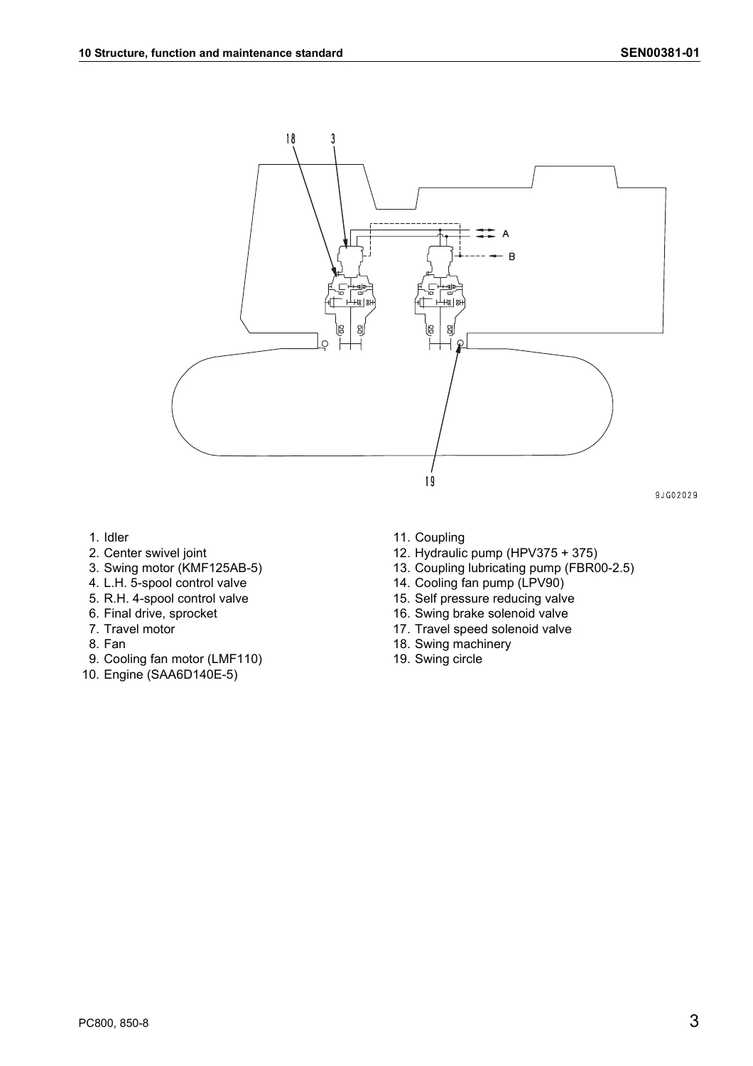
Swing operations are driven by dual KMF125AB-5 axial piston motors delivering 1,936 rpm rated speed through independent twin planetary reduction gearboxes with a reduction ratio of 35.716:1, meshing into the 112-tooth internal swing circle gear (ratio -8.615:1). The shop manual provides precise maintenance criteria for gear backlash across all planetary stages, axial bearing clearances, safety valve relief thresholds (27.9 MPa), and the hydraulic swing holding brake release circuit.
Standard Service Values and Powertrain Specifications
Accurate field diagnostics rely on precise benchmark specifications. This shop manual supplies complete engineering tolerances and service limit thresholds across every primary system:
- Engine Performance: High idle speed at 1,980 ± 50 rpm; low idle at 825 ± 25 rpm; rated working speed at 1,800 rpm. Minimum intake manifold boost pressure of 184 kPa (1,380 mmHg) at rated output; compression pressure standard of minimum 4.1 MPa (42 kg/cm²) at 200–250 rpm cranking speed (service limit 2.8 MPa).
- Engine Valve Clearances: Intake valve clearance set to 0.35 mm; exhaust valve clearance set to 0.57 mm (firing order 1-5-3-6-2-4).
- Hydraulic Circuit Relief Pressures: Normal boom RAISE relief pressure at 32.4 ± 1.0 MPa (330 ± 10 kg/cm²); Heavy Lift activated pressure increased to 33.8 ± 1.0 MPa (345 ± 10 kg/cm²); boom LOWER normal relief at 18.6 ± 1.9 MPa, increasing to 31.4 ± 1.0 MPa during Machine Push-Up mode. Arm relief pressure at 31.4 ± 1.0 MPa; bucket curl at 31.4 ± 1.0 MPa; travel circuit relief at 34.8 ± 1.0 MPa (355 ± 10 kg/cm²); and swing relief at 28.9 MPa (295 kg/cm²).
- Pilot and Control Pressures: Self-pressure reducing valve basic control pressure at 3.24 MPa (33 kg/cm²); PPC pilot valve output pressure at 2.9 MPa (30 kg/cm²) at full lever stroke; jet sensor differential output voltage ranging from minimum 2.54 V in neutral to 1.33 V under full travel stroke.
- Undercarriage & Wear Limits: Recoil spring free length of 1,553 mm with installed length of 1,290 mm under an installation load of 489.8 kN (49,986 kg); track link pitch standard of 260.6 mm (repair limit 263.6 mm); bushing outside diameter of 87.9 mm (reverse/turn limit 82.9 mm); track shoe bolt tightening torque of 784 ± 78 Nm (80 ± 8 kgm) plus 120° ± 10° torque-turn angle.
- Fluid Capacities: Engine oil pan capacity of 58 liters (53 L refill); swing machinery cases at 24.5 liters each; final drive cases at 20 liters each; hydraulic system total capacity of 800 liters (470 L refill); cooling system capacity of 104 liters; and fuel tank capacity of 980 liters.
Testing, Adjusting, and Troubleshooting Routines
When unexpected downtime occurs, the Komatsu PC800-8, PC800SE-8, PC800LC-8, PC850-8, PC850SE-8 Excavator Shop Manual streamlines fault isolation with structured testing and diagnostic procedures. Technicians can follow detailed instructions for setting the machine monitor into service diagnosis mode, displaying internal controller parameters, checking pump EPC solenoid currents (265 ± 50 mA in neutral, 575.5 ± 50 mA under load), and reading live error codes. The manual details specific troubleshooting paths for engine failure codes (such as CA115 engine speed sensor errors, CA449/CA559 common rail fuel pressure faults, and CA1228/CA1628 EGR valve servo issues), controller communication alarms (DA series), and hydraulic solenoid failures (DW and DX series).
For mechanical and hydraulic troubleshooting without fault codes (H-mode), the manual provides systematic cause-and-effect flowcharts addressing low work equipment speed, abnormal engine stalling, boom/arm hydraulic drift, travel tracking errors, and swing overrun. Each diagnostic flow leads directly to physical pressure testing ports, valve spool inspections, or cylinder internal seal bypass measurements, allowing technicians to resolve root causes efficiently.
Professional Workshop Capability and Instant Delivery
Equipping your maintenance department with the Komatsu PC800-8, PC800SE-8, PC800LC-8, PC850-8, PC850SE-8 Excavator Shop Manual ensures that every scheduled service, minor adjustment, and complete system rebuild is completed in strict accordance with original factory engineering standards. Adhering to genuine torque specifications, correct hydraulic air-bleeding sequences, and proper electronic calibration procedures prevents expensive component failures, eliminates diagnostic guesswork, and protects your investment in high-production mining assets.
This manual is delivered as an instant digital PDF download immediately following payment. There are no shipping delays, postal fees, or fragile paper manuals to worry about. The document is fully compatible with Windows, macOS, Android, and iOS devices, allowing you to view detailed circuit schematics and assembly steps directly on a laptop, workshop computer, or ruggedized mobile tablet in the service bay or field. You can zoom in on intricate hydraulic schematics or print out specific disassembly checklists and torque charts on demand.


Reviews
There are no reviews yet.