★ TRUSTED BY 321,897+ PROFESSIONALS WORLDWIDE
🏢
Trusted Business
Verified & Licensed
🛡️
Virus Free Files
100% Safe Downloads
🔒
Secure Payment
SSL Protected
Instant Delivery
Available Immediately
Sale!

LiuGong CLG909ECR Hydraulic Excavator Service Manual 202409002 2024 PDF

Original price was: $49.95.Current price is: $29.95.

Complete 2024 LiuGong CLG909ECR Hydraulic Excavator service manual 202409002 covering YANMAR 4TNV98C applications, machine parameters, hydraulic and electrical systems, testing and adjustment, DTC and system fault diagnosis, removal and installation procedures, and hydraulic/electrical/A/C schematics.

Instant PDF Download
Available immediately
💾
Save to Your Device
Download & keep forever
🛡️
Antivirus Scanned
100% virus-free
🌍
Trusted Worldwide
175,000+ customers

Description

LiuGong CLG909ECR Hydraulic Excavator Service Manual 202409002 2024 PDF

The LiuGong CLG909ECR Hydraulic Excavator Service Manual 202409002 2024 PDF is a workshop-focused service reference for the CLG909ECR hydraulic excavator. The cover identifies applications for CLG909ECR machines with the YANMAR 4TNV98C engine in EPA Tier 4f / EU Stage III B and EU Stage V configurations, plus the CLG909ECR New2 Double Boom with YANMAR 4TNV98C. Across 854 PDF pages, it brings together machine parameters, system construction and operating principles, maintenance limits, testing and adjustment methods, fault diagnosis, component removal and installation, disassembly and assembly procedures, and system schematics.

This is not just a routine maintenance booklet. The manual is organized as a technical guide and workshop guide, moving from system understanding and measured standards into diagnosis and physical repair work. It is designed to help users and technicians trace a symptom, test the relevant system, identify an abnormal component, compare measurements with service data, and then follow the applicable removal, installation, disassembly or assembly procedure.

File Details

  • Manual type: Service Manual
  • Brand / model: LiuGong CLG909ECR Hydraulic Excavator
  • Additional model shown: CLG909ECR New2 Double Boom
  • Engine coverage: YANMAR 4TNV98C; the parameter section identifies engine model 4TNV98C-SLY
  • Document number: 202409002
  • Date: September 6, 2024
  • Language: English
  • Pages: 854
  • File format: PDF

Workshop Information for the CLG909ECR

The LiuGong CLG909ECR service manual explains the machine by system rather than presenting isolated procedures. The structural section covers the power system, undercarriage and track travel components, hydraulic elements and working circuits, work equipment, air-conditioning and electrical controls. Hydraulic coverage is especially extensive: main pump, main control valve, center joint, explosion relief valve, hand and travel pilot valves, cushion valve, travel motor and speed reducer, slewing motor and speed reducer, cylinders, hydraulic tank and oil source block are all addressed. Working-circuit explanations include boom raise and lower, arm extend and retract, bucket movements, left and right slewing, forward and reverse travel, boom deflection, auxiliary circuits, attachment slewing and dozer functions.

The electrical section covers engine control, the display system, LCD and button-panel functions, user menus, working modes, automatic idling, overheating protection, travel-speed control and selected machine circuits. Circuit descriptions include travel two-speed, starting, charging, power-limit solenoid valve operation and the electronic proportional relief-valve circuit. The attached drawings at the end of the manual add complete hydraulic, machine electrical and A/C electrical schematic coverage for the configurations shown in the document.

IMAGES PREVIEW

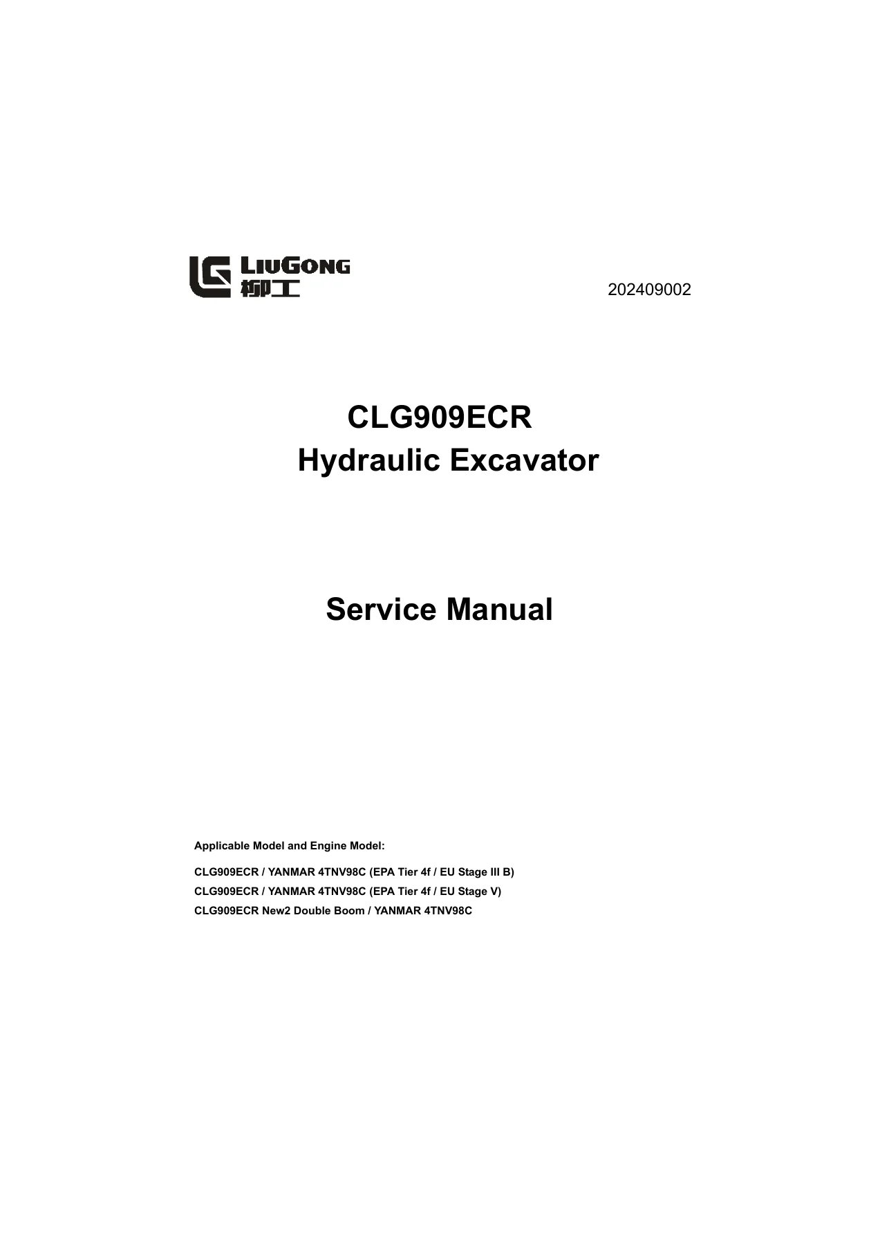
LiuGong CLG909ECR Hydraulic Excavator Service Manual 202409002 2024 PDF — PDF page 1 preview
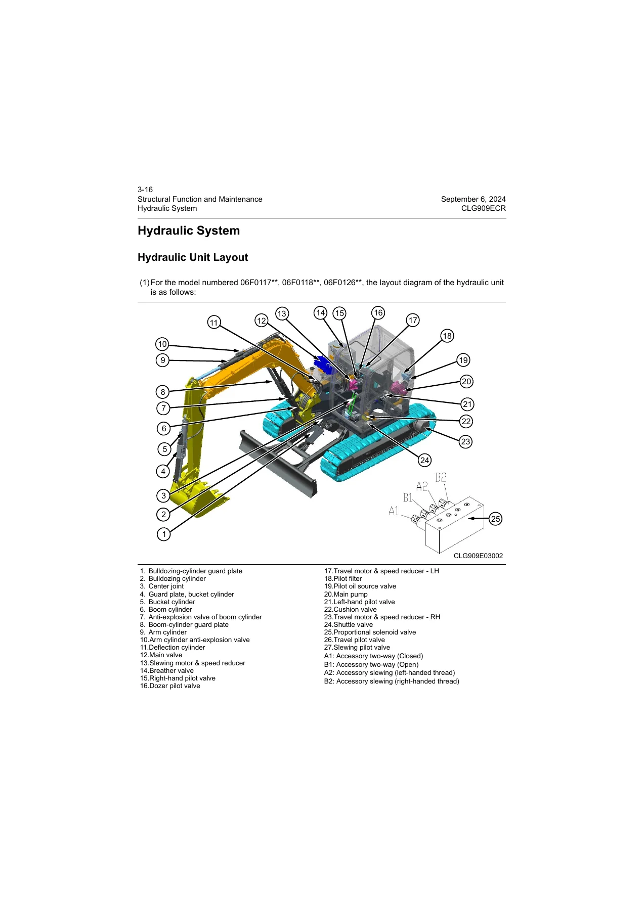
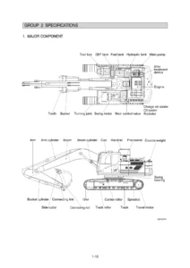
LiuGong CLG909ECR Hydraulic Excavator Service Manual 202409002 2024 PDF — PDF page 50 preview
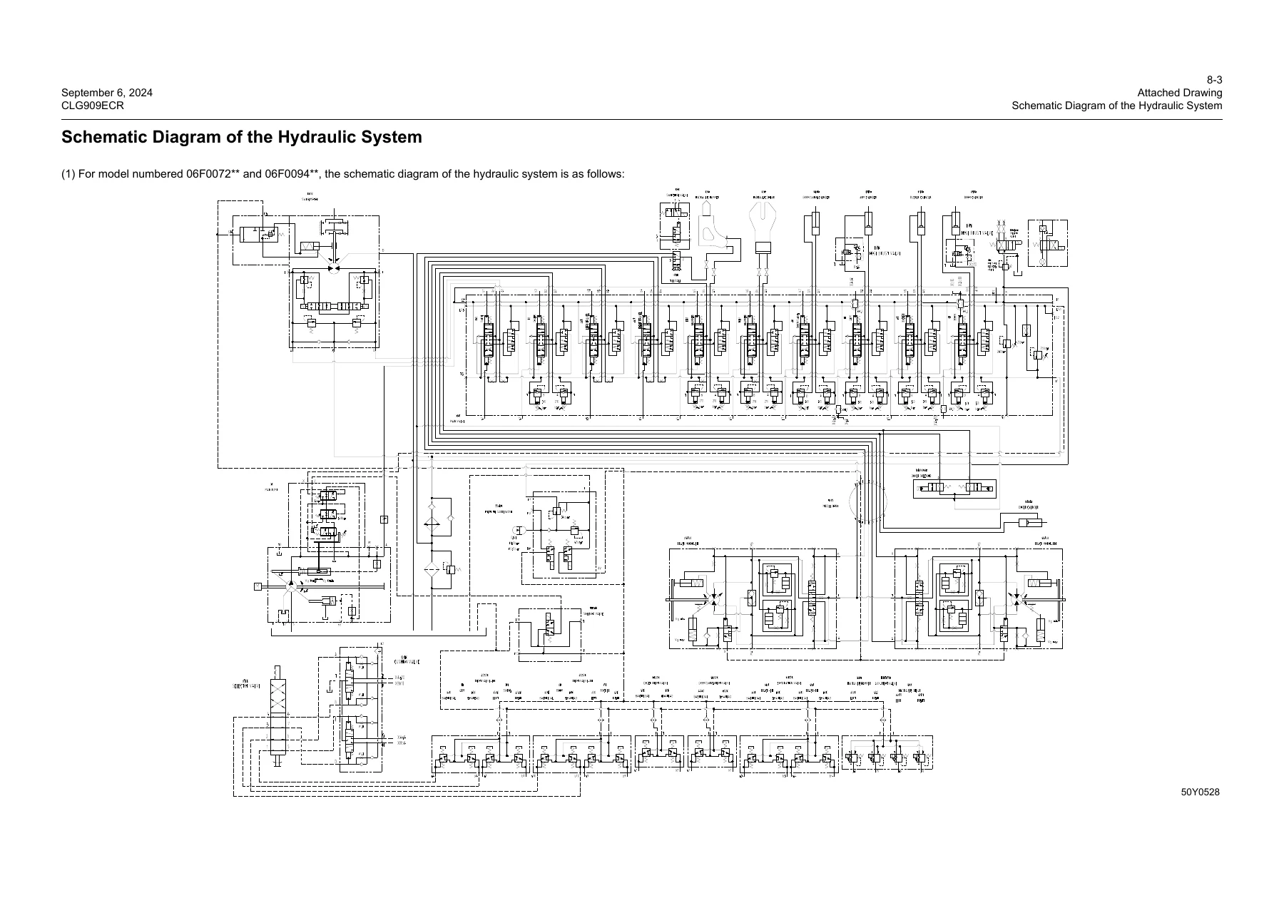
LiuGong CLG909ECR Hydraulic Excavator Service Manual 202409002 2024 PDF — PDF page 841 preview

Service Data, Parameters and Adjustment References

The parameters section provides practical machine and component data that can be used while inspecting, testing or repairing the excavator. The manual lists an operating weight of 8700 kg {19183.5 lb}, standard bucket capacity of 0.28 m3 {9.89 cu ft}, high/low driving speeds of 0~4.75 and 0~2.35 km/h, slewing speed of 10.5 r/min and a 12 V electrical system. The engine data identifies the YANMAR 4TNV98C-SLY as a four-cylinder, water-cooled engine with 98 mm x 110 mm bore and stroke and 3.319 L displacement. It also provides rated and net power, torque, no-load speeds, starter and alternator information.

Hydraulic and service-reference material includes general machine bolt tightening torques, pipe-fitting torque data, component weight references, lubricants and coating materials, oil specifications, oil-change intervals and approximate filling capacities. The manual gives examples such as 500 working hours for engine oil, 1000 hours for slewing-drive and travel-speed-reducer gear oil, and 2000 hours for hydraulic oil and the cooling system. It specifies API CJ-4 engine-oil grades, API GL-5 gear oils and ISO VG hydraulic-oil grades for stated ambient-temperature ranges. Detailed component sections also provide pressure settings, clearances, wear limits, replacement criteria and service checks for items such as the main pump, control valve, center joint, track components, travel drive and slewing drive.

Testing and Fault Diagnosis

The test-and-adjustment chapter gives procedures for verifying machine performance before parts are removed. It includes diesel-engine speed, travel speed, measured driving speed, travel deviation, slewing service braking angle, slewing speed, slewing-bearing clearance, cylinder action time, cylinder settlement, control-lever force and stroke, boom lifting with slewing, pilot-pressure checks, secondary pilot pressure and main-pressure measurement and adjustment. Other tests cover valve-lash adjustment, oil-pressure measurement, track-tension measurement and adjustment, release of residual hydraulic pressure, air bleeding, compressor-belt tension, diode checking, and travel-motor and speed-reducer performance testing.

Fault diagnosis is a major part of the CLG909ECR Hydraulic Excavator Service Manual 202409002. It starts with precautions, basic checks and fault classification, then provides Diagnostic Trouble Code procedures for machine electrical and sensor faults. Separate electrical-system diagnosis and hydraulic/mechanical diagnosis sections guide the technician through symptoms and test paths. The hydraulic/mechanical fault trees include problems such as sharp engine-speed drop or stalling under hydraulic load, hydraulic-oil emulsification, abnormal boom/arm/bucket action, slewing faults, excessive slewing drift or braking vibration, and travel faults. This structure lets the manual connect a symptom to pressure checks, circuit checks, component inspection and the next repair step instead of treating troubleshooting as guesswork.

Removal, Installation and Component Repair

Once a fault has been isolated, the removal-and-installation chapter covers a wide range of major CLG909ECR assemblies. Power-system procedures include the diesel engine assembly, fuel tank, radiator, valve cover, injectors, cylinder head and engine seals. Track-travel procedures cover rollers, track assembly, sprocket, idler and tensioner, and slewing bearing. Hydraulic procedures include the center joint, hydraulic tank, main control valve, main pump, travel pilot valve, hand pilot valve, travel motor and speed reducer, and slewing motor and speed reducer, with disassembly and assembly procedures for several of these components.

Work-implement procedures cover the bucket, link and lever, arm, boom, complete work implement, bucket cylinder, arm cylinder, boom cylinder, cylinder disassembly/assembly and dozer blade. The manual also includes A/C evaporator and compressor procedures plus cab and floor-frame removal and installation. Procedure pages combine step sequences with illustrations, cautions, lifting information, tightening requirements and reassembly notes where provided.

Complete PDF Bookmark Tree

Complete Bookmarks

The complete bookmarks in the “LiuGong CLG909ECR Hydraulic Excavator Service Manual 202409002 2024 PDF” are as follows:

Contentsp. 3
1 Safety Instructionsp. 5
Safety Precautionsp. 8
Precautions for Lifting and Collaborative Operationsp. 16
2 Basicsp. 19
How to Read the Manualp. 21
Marking of Revised Versionp. 23
General Torque Specificationsp. 24
Unit Conversion Tablep. 27
Cable Identification Methodsp. 28
Coating Materialsp. 31
Weight Tablep. 32
Specifications for Oil Applicationp. 33
3 Structural Function and Maintenancep. 35
Power Systemp. 39
Diesel Engine Related Partsp. 39
Water Radiator and Hydraulic Oil Radiatorp. 39
Track Travel Systemp. 40
Track Framep. 40
Tensionerp. 41
Idlerp. 42
Carrier Rollerp. 44
Track Rollerp. 46
Sprocketp. 48
Trackp. 49
Hydraulic Systemp. 50
Hydraulic Unit Layoutp. 50
Hydraulic Elementsp. 52
Main Pump Assemblyp. 52
Main Control Valvep. 61
Center Jointp. 92
Explosion Relief Valvep. 95
Hand Pilot Valvep. 96
Travel Pilot Valvep. 98
Cushion Valvep. 101
Travel Motor and Speed Reducerp. 104
Slewing Motor and Speed Reducerp. 124
Cylinderp. 163
Hydraulic Tank Assemblyp. 166
Oil Source Blockp. 173
Hydraulic Principlep. 177
Main Hydraulic Circuitp. 177
Pilot Circuitp. 181
Working Circuit of Boom Liftingp. 182
Working Circuit of Boom Loweringp. 184
Working Circuit of Arm Stretchingp. 186
Arm Retraction Circuitp. 188
Circuit of Bucket Stretchingp. 190
Bucket Retraction Working Circuitp. 192
2nd Boom Stretching Circuit (optional)p. 194
2nd Boom Stretching Circuit (Optional)p. 196
Working Circuit of Left Swingp. 198
Working Circuit of Right Swingp. 200
Travel Forward (Fast)p. 202
Travel Backward (Slow)p. 204
Deflect to the Leftp. 206
Deflect to the Rightp. 208
Auxiliary One-wayp. 210
Auxiliary Double-way (Opened)p. 212
Attachment Swing (Clamping)p. 214
Auxiliary Swing (Release)p. 216
Dozer Blade Liftingp. 218
Lowering of Dozerp. 220
Dozer Floatingp. 222
Work Implementp. 224
Maintenance References of Main Componentsp. 224
Maintenance References of Arm Partp. 228
Maintenance References of Bucket Partp. 231
Dozer Maintenance Referencep. 233
A/C Systemp. 235
Electrical Systemp. 236
Engine Controlp. 236
Display Systemp. 238
Displayp. 239
LCD Part of Displayp. 241
Display Button Panelp. 253
User Menup. 269
Electrical Control Systemp. 286
Working Modep. 286
Automatic Idling Functionp. 287
Overheating Protection Functionp. 288
Travel Speed Control Functionp. 289
Various Componentsp. 290
Descriptions of Partial Circuitsp. 302
Travel Two-Speed Circuitp. 302
Starting Circuitp. 303
Charge Circuitp. 304
Power Limit Solenoid Valve Operation Circuitp. 305
Working Circuit of Electronic Proportional Relief Valvep. 306
4 Parametersp. 307
Basic Parametersp. 309
Performance Parameters of Diesel Enginep. 315
Performance Parameters of Machinep. 316
5 Test and Adjustmentp. 319
Performance Test of Machinep. 321
Diesel Engine Speedp. 322
Travel Speed (Idling Speed)p. 322
Driving Speed (Measured Speed)p. 323
Travel Deviationp. 324
Slewing Service Braking Anglep. 325
Slewing Speedp. 327
Slewing Bearing Clearancep. 328
Action Time of Cylinderp. 329
Cylinder Settlementp. 332
Operating Force of Control Leverp. 333
Control Lever Strokep. 334
Boom Lifting and Slewing Actionp. 334
Pilot Pressure Measurement and Adjustmentp. 335
Measurement of the Secondary Pilot Pressurep. 337
Main Pressure Measurement and Adjustmentp. 339
Other Testsp. 341
Adjustment of Valve Lashp. 341
Oil Pressure Measurementp. 344
Measurement and Adjustment of Track Tensionp. 344
Measurement of the Track Tensionp. 344
Adjustment of Track Tensionp. 345
Release Residual Pressure in Hydraulic Linesp. 346
Air Bleeding of Various Devicesp. 347
Adjustment of Compressor Belt Tensionerp. 349
Diode Checking Procedurep. 350
Performance Test of Travel Motor and Speed Reducerp. 351
6 Fault Diagnosisp. 353
Precautions for Fault Diagnosisp. 357
Basic Fault Detection Before Maintenancep. 358
Classification of Faultsp. 361
Diagnostic Trouble Code (DTC)p. 362
DTC 101003 High Battery Voltagep. 362
DTC 101017 Low Battery Voltagep. 367
DTC 111001 System Charging Faultp. 375
DTC 121015 Oil Pressure Switch Disconnectedp. 378
DTC 121018 Low Oil Pressurep. 381
DTC 121305 Hand Pilot Pressure Switch Disconnectedp. 383
DTC 121405 Foot Pilot Pressure Switch Disconnectedp. 388
DTC 121604 Air Filter Switch Shorted to Groundp. 392
DTC 121615 Air Filter Cloggingp. 395
DTC 131200 Extremely High Hydraulic Oil Temperaturep. 397
DTC 131203 Hydraulic Oil Temperature Sensor Voltage Above Range Valuep. 399
DTC 131204 Hydraulic Oil Temperature Sensor Voltage Below Range Valuep. 402
DTC 131215 High Hydraulic Oil Temperaturep. 406
DTC 131216 Extremely High Hydraulic Oil Temperaturep. 408
DTC 131303 Fuel Level Sensor Voltage Above Range Valuep. 410
DTC 131304 Fuel Level Sensor Shorted to Groundp. 417
DTC 131317 Low Fuel Levelp. 424
DTC 131703 Sensor Power (5V) Shorted to Power Supply of Machinep. 429
DTC 131704 Sensor Power (5V) Shorted to Groundp. 433
DTC 151004 Attachment Confluence Solenoid Valve Shorted to Groundp. 437
DTC 151005 Attachment Confluence Solenoid Valve Open-Circuited Or Shorted to Power Supplyp. 441
DTC 151204 Travel Shift Solenoid Shorted to Groundp. 445
DTC 151205 A2 Travel Shift Solenoid Valve Open-Circuited Or Shorted to Power Supplyp. 449
DTC 201004 Travel Alarm Shorted to Groundp. 454
DTC 231012 Abnormal Controller Heartbeatp. 458
DTC 251004 Fuel Pump Relay Shorted to Groundp. 461
DTC 251005 Fuel Pump Relay Open Circuited Or Shorted to Power Supplyp. 464
DTC 261011 GPS Antenna Faultp. 468
DTC 261111 GPS Module Faultp. 470
DTC 261211 GSM Signal Faultp. 471
DTC 261311 GPRS Connection Faultp. 473
DTC 261411 SIM Card Read Faultp. 473
DTC 261512 Abnormal GPS Heartbeatp. 475
DTC 261611 Automatic Locking Level 1 Abnormal GPS Heartbeat, the Machine is Limited for Usep. 478
DTC 261614 Forced Locking Level 1 Payment Expired, Machine Is Limited for Usep. 481
DTC 261711 Automatic Locking Level 2 Abnormal GPS Heartbeat, and the Machine is Prohibited for Usep. 482
DTC 261714 Forced Locking Level 2 Payment Expired, and Machine Is Prohibited for Usep. 484
DTC 261814 Pay Due Loan Promptlyp. 484
DTC 281603 Bucket Pilot Pressure Sensor Voltagee Exceeds Upper Limitp. 485
DTC 281604 Lifting Pressure Sensor Voltage Exceeds Lower Limitp. 489
Fault Diagnosis of Electrical Systemp. 493
E1 – Troubleshooting Solution for Battery Power Lossp. 493
E2 – Troubleshooting Solution for Battery Abnormaltyp. 496
E3 Automatic Slowdown Failedp. 499
E4 – Engine Cannot Be Startedp. 503
E5 – Engine Shuts Down During Operationp. 512
E6 Engine Cannot Shut Downp. 515
E7 – All the Work Implements, Revolving and Travel Cannot Movep. 519
E8 – Display Panel Shows Nothingp. 526
E9- Incorrectly Displayed Hydraulic Oil Temperaturep. 530
E10 – Fuel Gauge Cannot Display Correct Valuep. 533
E11 – Windshield Wiper Does Not Workp. 539
E12 – Travel Alarm Does Not Soundp. 545
E13 – A/C Panel Does Not Workp. 550
E14 – A/C Blows No Air Or Air Volume Abnormalp. 554
E15 – Abnormal A/C Refrigerationp. 557
E16 – Pressure Switch Faultp. 560
E17 – Abnormal Voltagep. 562
Fault Diagnosis of the Hydraulic System and Mechanical Systemp. 564
System Table of the Hydraulic System and Mechanical Systemp. 564
H1 Engine Speed Drops Sharply or Engine Stallsp. 565
H2 Hydraulic Oil Emulsificationp. 565
H3 Abnormal Increase of Hydraulic Oil Temperaturep. 566
H4 Abnormal Sound Around Main Pumpp. 567
H5 When Engine Is Started, All Operations Are Unresponsive/Slow in Responsep. 568
H6 Boom, Arm Or Bucket Has No Actionp. 569
H7 Boom, Arm Or Bucket Has Slow Actionp. 570
H8 Weak Actions of the Boom, Arm Or Bucketp. 571
H9 Boom, Arm Or Bucket Has Large Drift Distance (Cannot Stop)p. 572
H10 Left and Right Slewing Have No Actionp. 573
H11 Slewing of Single Side Has No Actionp. 574
H13 When Slewing Is Stopped, It Has a Large Brake Angle/Excessive Vibrationp. 575
H14 Travel Has No Actionp. 576
H15 Traveling of Single Side Has No Actionp. 577
H16 Travel Deviationp. 578
H17 Travel Speed Unchanged/ too Slow/ too Fastp. 579
7 Removal and Installationp. 581
Overviewp. 583
Power Systemp. 584
Removal and Installation of Diesel Engine Assemblyp. 584
Removal and Installation of Fuel Tank Assemblyp. 594
Removal and Installation of Radiator Assemblyp. 599
Removal and Installation of Valve Coverp. 607
Removal and Installation of Injector Assemblyp. 609
Removal and Installation of Cylinder Head Assemblyp. 611
Removal and Installation of Engine Front Sealp. 613
Removal and Installation of Engine Rear Sealp. 614
Track Travel Systemp. 615
Removal and Installation of Track Rollerp. 615
Removal and Installation of Carrier Rollerp. 617
Removal and Installation of Track Assemblyp. 618
Removal and Installation of Sprocketp. 621
Removal and Installation of Idler and Tensioner Assemblyp. 622
Removal and Installation of Slewing Bearingp. 624
Covering Partsp. 629
Removal and Installation of Engine Hoodp. 629
Removal and installation of Counterweightp. 631
Hydraulic Systemp. 633
Removal and Installation of Center Joint Assemblyp. 633
Disassembly and Assembly of Center Jointp. 636
Removal and Installation of Hydraulic Tankp. 641
Removal and Installation of Main Control Valve Assemblyp. 647
Disassembly and Assembly of Main Control Valvep. 649
Removal and Installation of Main Pump Assemblyp. 658
Removal and Installation of Main Pump Assemblyp. 663
Removal and Installation of Travel Pilot Valve Assemblyp. 681
Removal and Installation of Hand Pilot Valve Assemblyp. 684
Disassembly and Assembly of Hand Pilot Valve Assemblyp. 687
Removal and Installation of Travel Motor & Speed Reducerp. 692
Disassembly and Assembly of Travel Motor & Speed Reducer Assemblyp. 697
Removal and installation of Travel Motor & Speed Reducerp. 745
Removal and Installation of Slewing Motor & Speed Reducerp. 760
Work Implementp. 769
Removal and Installation of Bucketp. 769
Removal and Installation of Link and Leverp. 771
Removal and Installation of Armp. 774
Removal and Installation of Boomp. 778
Removal and Installation of Work Implement Assemblyp. 789
Removal and Installation of Bucket Cylinder Assemblyp. 792
Removal and Installation of Arm Cylinder Assemblyp. 796
Removal and Installation of Boom Cylinder Assemblyp. 800
Disassembly and Assembly of Cylinderp. 805
Removal and Installation of Dozer Bladep. 815
A/C Systemp. 818
Removal and Installation of A/C Evaporator Assemblyp. 818
Removal and Installation of A/C Compressor Assemblyp. 822
Cabp. 825
Removal and Installation of Cabp. 825
Removal and Installation of Floor Frame Assemblyp. 832
8 Attached Drawingp. 839
Schematic Diagram of the Hydraulic Systemp. 841
Electrical System Schematic Diagramp. 844
A/C Electrical Schematic Diagramp. 847
INDEXp. 849

Chapters Covered

  • 1. Safety Instructions
    • Safety Precautions
    • Precautions for Lifting and Collaborative Operations
  • 2. Basics
    • How to Read the Manual and revised-version marking
    • General Torque Specifications and unit conversion
    • Cable Identification Methods
    • Coating Materials and Weight Table
    • Specifications for Oil Application
  • 3. Structural Function and Maintenance
    • Power System
    • Track Travel System
    • Hydraulic System – hydraulic unit layout, elements and hydraulic principles
    • Work Implement maintenance references
    • A/C System
    • Electrical System – engine control, display, control functions and selected circuits
  • 4. Parameters
    • Basic Parameters
    • Performance Parameters of Diesel Engine
    • Performance Parameters of Machine
  • 5. Test and Adjustment
    • Performance Test of Machine
    • Diesel engine, travel, slewing, cylinder and control measurements
    • Pilot and main pressure measurement and adjustment
    • Other Tests – valve lash, oil pressure, track tension, air bleeding, compressor belt, diode and travel-drive tests
  • 6. Fault Diagnosis
    • Precautions for Fault Diagnosis and Basic Fault Detection Before Maintenance
    • Classification of Faults
    • Diagnostic Trouble Code (DTC) diagnosis
    • Fault Diagnosis of Electrical System
    • Fault Diagnosis of the Hydraulic System and Mechanical System
  • 7. Removal and Installation
    • Power System
    • Track Travel System
    • Covering Parts
    • Hydraulic System
    • Work Implement
    • A/C System
    • Cab and floor frame
  • 8. Attached Drawing
    • Schematic Diagram of the Hydraulic System
    • Electrical System Schematic Diagram
    • A/C Electrical Schematic Diagram

Taken together, these chapters provide a continuous workshop path from safety and baseline specifications through system understanding, measured testing, diagnosis and repair. For technicians dealing with a weak hydraulic function, abnormal travel or slew behavior, electrical fault code, cylinder drift, component leakage, undercarriage wear or a major assembly replacement, the manual provides the relevant system explanation and service procedure in the same document.

Service, Diagnose and Repair with the Correct CLG909ECR Reference

The LiuGong CLG909ECR Hydraulic Excavator Service Manual 202409002 2024 PDF supports detailed workshop jobs ranging from pressure and performance checks to hydraulic-component service, electrical diagnosis, undercarriage work, engine-related removal procedures, work-equipment repairs and major component removal and installation. Its value is the ability to work from model-specific procedures, diagrams, limits, pressures, torque references and test standards instead of relying on general repair assumptions.

After purchase, the manual is delivered as an instant PDF download – there is no physical book and no shipping wait. Open it on a computer, tablet or phone, keep it available alongside the machine, and print the pages you need for the job.
Reviews

There are no reviews yet.

Be the first to review “LiuGong CLG909ECR Hydraulic Excavator Service Manual 202409002 2024 PDF”

What Our Customers Say

★★★★★ Live reviews from customers
Loading customer reviews...
0
    0
    Your Cart
    Your cart is emptyReturn to Shop
    🛒
    Recently Purchased
    🕒 verified order