
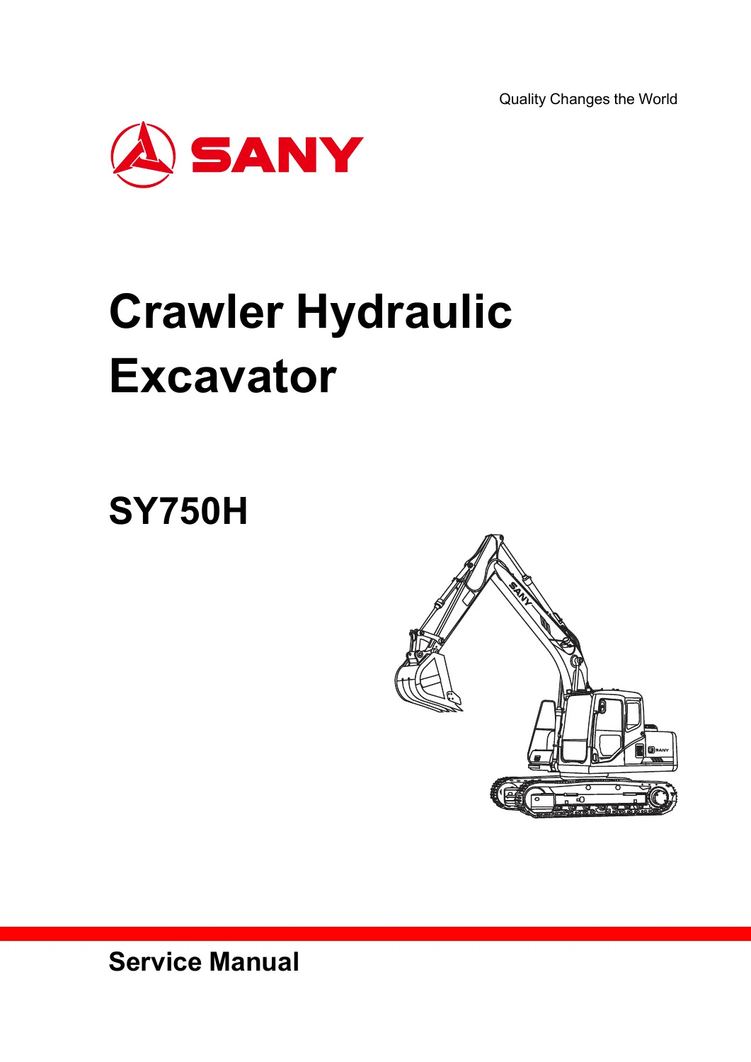
SANY SY750H Hydraulic Excavator Service Manual PDF Download
Original price was: $49.95.$31.95Current price is: $31.95.
SANY SY750H hydraulic excavator service manual covering 588 pages of specifications, hydraulics, electrical controls, testing, troubleshooting and repair procedures.
Description
SANY SY750H Hydraulic Excavator Service Manual
The SANY SY750H hydraulic excavator service manual is a 588-page workshop reference built around the SY750H and its service, adjustment, diagnostic and disassembly requirements. The document identifies the excavator model directly and includes an engine feature curve for the 6WG1X, extensive hydraulic-system material, electrical control information, testing procedures and a dedicated trouble-diagnosis chapter. It is structured for technicians who need more than general operating information: the manual moves from machine specifications and system function into standard values, measurement, adjustment, fault tracing and component removal or installation.
Manual and File Details
- Brand: SANY
- Model: SY750H Hydraulic Excavator
- Manual type: Service / Workshop / Repair
- Language: English
- Pages: 588
- Format: PDF
- Manual marking: Service Manual-10-2021
- Publisher shown: Sany Heavy Machinery Limited / Sany Group
Machine, Engine and Hydraulic Coverage
Applicability is centered on the SY750H. The technical section gives machine dimensions and working range, while the structure section follows the engine and cooling system, transmission train, undercarriage, hydraulic assemblies, working device, air conditioning, engine control, electrical controls and display system. The engine feature-curve section names the 6WG1X. Hydraulic content includes the SY750H pump arrangement and a Kawasaki K3V/K5V swashplate-type axial plunger pump identified as K3V280DTH, followed by pilot-pump, regulator and control-valve material.
How the 588 Pages Are Organized
- Preface
- Reading Method of Service Manual
- Explanation on Terms for Maintenance Standards
- Handling of Electrical Component and Hydraulic Components
- Safety
- Instructions on Safety Signs
- General Notices
- Preparatory Work before Maintenance
- Notices for Maintenance/Repair
- Other Notices
- Technical Specification
- Specified size
- Technical Specification
- Table of Weight
- Engine oil, fuel and coolant
- Feature curve of engine
- Structure, function and maintenance standard
- Engine and Cooling System
- Transmission Train
- Lower travelling device
- Hydraulic system (Part 1)
- Hydraulic system, Part 2
- Hydraulic system, Part 3
- Working Device
- Air conditioning system
- Engine control
- Electrical Control System
- Display system
- Standard value of components
- Table of standard values for engine-related parts
- Table for standard value of body-related parts
- Testing and Adjustment
- Measurement of Color of Exhaust Gas
- Adjust the valve clearance
- Measurement of compression pressure
- Inspection and adjustment of injection timing
- Measurement of engine oil pressure
- Inspection and adjustment of hydraulic pressure in hydraulic oil ways for working device, slewing and travelling
- Measurement of output pressure of electromagnetic valve
- Measurement of output pressure of pilot valve
- Inspection of hydraulic settlement of working device
- Measurement of oil leakage
- Air Bleeding for Every Device
- Inspection on sensor
- Trouble diagnosis and troubleshooting
- Precautions during Trouble Diagnosis
- Inspection before Trouble Diagnosis
- Category and steps of trouble diagnosis
- Connector
- Trouble diagnosis when current trouble code is displayed
- Trouble Diagnosis for Electrical System (Mode E)
- Trouble diagnosis for hydraulic and mechanical systems (mode H)
- Disassembly and assembly
- General information for disassembly and assembly
- Engine and cooling system
- Power train
- Undercarriage
- Upper structure
- Hydraulic system
- Work equipment
What You Can Service and Check
The service content is unusually broad. Engine-related work includes valve-clearance adjustment, compression-pressure measurement, injection-timing inspection and adjustment, engine-oil-pressure measurement and engine-speed-sensor adjustment. The chassis and working-equipment material covers the slewing support bearing, crawler plate tension, working-device hydraulic settlement and oil leakage. Hydraulic tests cover pressure in the working-device, slewing and travelling circuits, control oil pressure, electromagnetic-valve output pressure and pilot-valve output pressure. The manual also includes residual-pressure release, air bleeding and sensor inspection, giving the reader both system theory and concrete test procedures.
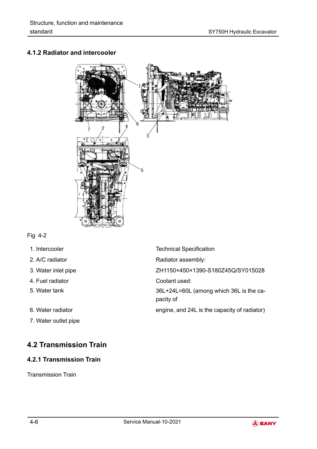
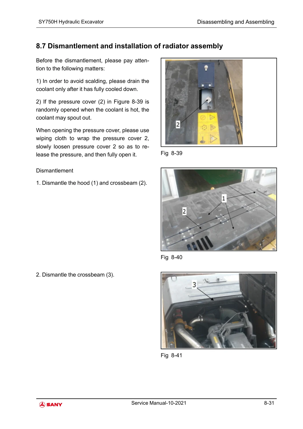
The structure-and-function chapter is useful before disassembly because it explains how the major assemblies operate. It covers the radiator and intercooler, travelling reducer, slewing reducer and bearing, crawler carrier and tensioning mechanism, guide and drive wheels, track, hydraulic tank and filters, pump, regulator, control valve, slewing motor, central slewing connector, running motor, pilot controls, accumulator and working device. Air-conditioning pages address the control panel, circuit schematic, refrigeration principle, compressor, clutch, condenser, expansion valve, evaporator, drier, pressure switch, refrigerant and compressor oil. Electrical-control pages cover engine-pump combined control, valve control, protection for low engine-oil pressure and high coolant temperature, preheating and pressure/fuel-level sensors.
Selected Specifications and Reference Values
- Overall length (transportation posture): 12865 mm
- Overall width: 4030/3430 mm
- Overall height (transportation posture): 4855 mm
- Cab-roof height: 3800 mm
- Standard track shoe width: 650 mm
- Track gauge: 3380/2780 mm
- Minimum ground clearance: 875 mm
- Tail swing radius: 4220 mm
- Track length: 5865 mm
- Maximum digging height: 11055 mm
- Maximum loading height: 7210 mm
- Maximum digging depth: 7630 mm
- Maximum vertical excavation depth: 4300 mm
- Maximum digging reach: 12050 mm
- Minimum swing radius: 5515 mm
- Engine model shown in engine curve: 6WG1X
- Engine oil capacity: 52 L
- Coolant capacity: 60 L total: 36 L engine + 24 L radiator
Additional hydraulic reference material states a 700 L hydraulic-oil tank with 630 L effective capacity and 10 μm suction filtration. The slewing-motor information identifies model M5X180CHB-10A-8PA/290-RG20D22G17-140, theoretical displacement of 180.1 cm3/rev, a 28.5 MPa safety-valve setting and 2.7-4.9 MPa brake releasing pressure. These figures sit alongside component standard-value tables, so measurements can be compared against manual data rather than judged by feel alone.
Fault Diagnosis and Troubleshooting
The diagnostic chapter starts with precautions, pre-diagnosis inspection and connector identification, then separates displayed trouble codes from electrical-system and hydraulic/mechanical symptom diagnosis. The displayed-code section explicitly covers E101, E102, E103, E104, E105, E201, E202, H402, P101, P301, P401, P501 and P601. Examples include controller internal faults, abnormal controller temperature, sensor power supply, memory and CPU errors, low or high supply voltage, high hydraulic-oil temperature, low engine-oil pressure, high coolant temperature, low fuel level, blocked air filter and water level in the oil-water separator. Mode E includes symptoms such as engine no-start, engine that will not stop, automatic idle failure, weak boom/arm/bucket action, slow travel and display faults; Mode H addresses hydraulic and mechanical behavior.
Use the Correct Data at the Machine
With this PDF at hand, a technician can trace an SY750H hydraulic or electrical complaint, check pressures and sensor outputs, adjust service settings, interpret displayed trouble codes, understand circuit operation and follow removal/installation work from the same manual. Having the specified dimensions, capacities, standard values and diagnosis steps beside the excavator helps keep decisions tied to the documented SY750H procedure instead of memory or guesswork. The manual is supplied as an instant PDF download as soon as payment completes: there is no shipping delay, and the file can be read on a phone, tablet, laptop or workshop PC and printed for bench use.

Reviews
There are no reviews yet.