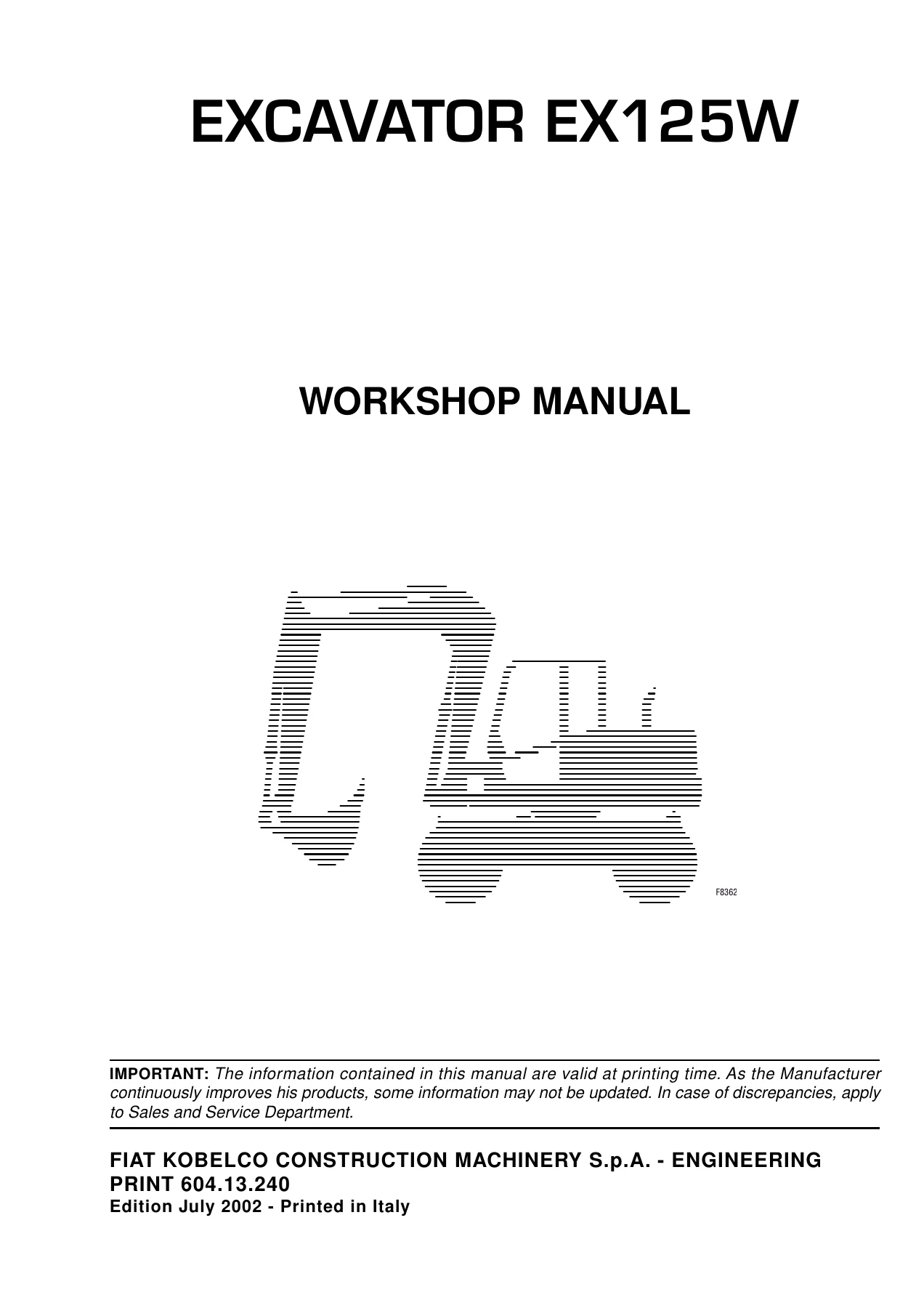
Fiat Kobelco EX125W Excavator Workshop Service Repair Manual 604.13.240 – July 2002 PDF Download
$49.95 Original price was: $49.95.$29.95Current price is: $29.95.
Comprehensive Fiat Kobelco EX125W wheeled excavator workshop manual covering specifications, superstructure, undercarriage, front attachment, hydraulic and electrical systems, troubleshooting, performance testing, and PERKINS 1004.40T engine service and overhaul. Print 604.13.240, Edition July 2002, 1094 pages in English.
Description
Fiat Kobelco EX125W Excavator Workshop Service Repair Manual
The Fiat Kobelco EX125W Excavator Workshop Service Repair Manual 604.13.240 – July 2002 PDF Download is a detailed technical repair reference for the EX125W wheeled excavator. Prepared for skilled technicians, it covers the machine from general specifications and system operating principles through component removal, disassembly, inspection, assembly, troubleshooting and operational performance testing. The manual also contains a substantial engine section for the PERKINS 1004.40T used in the EX125W.
This is a broad workshop-level manual rather than a basic operator guide. Its 11 main sections cover the upperstructure, wheeled undercarriage, front equipment, hydraulic and electrical systems, diagnostics, test procedures and engine repair. Technical drawings, hydraulic layouts, component illustrations, dimensional data, adjustment information and repair sequences are distributed throughout the manual to support practical workshop work.
File Details
- Manual type: Workshop Manual – Excavator
- Brand: Fiat Kobelco Construction Machinery
- Machine type: EX125W
- Print number: 604.13.240
- Edition: July 2002
- Language: English
- Pages: 1094
- File format: PDF
EX125W Technical and Repair Information
The manual starts with machine identification, construction features and specification data before moving into the repair sections. The EX125W specification material includes dimensions, digging performance, lifting capacity and filling information. The engine is identified as a PERKINS 1004.40T, with four cylinders, 3990 cm3 displacement and 100×127 mm bore and stroke. The specification section gives setting power figures of 74.5 kW to ISO/TR14396 and 67 kW to 80/1269 CEE, together with rated speed, hydraulic performance and machine operating data.
The hydraulic information is especially extensive. The EX125W uses a Load Sensing closed-centre equipment system and a CSS Cross Sensing System swing circuit. General specification data identifies two variable-displacement main pumps, with equipment/travel output up to 150 l/min at 2000 rev/min and a maximum operating pressure of 350 bar, while the upperstructure swing circuit is specified at up to 53 l/min and 310 bar. Later chapters go considerably further, explaining individual pumps, regulators, control valves, pilot circuits, accumulators, steering and brake hydraulics, travel circuits and system diagrams.
Workshop procedures are supported by tightening values, inspection information, service data and illustrated component sequences. Examples range from cab, counterweight and superstructure removal to hydraulic pump overhaul, control-valve servicing and hose/connection practices. The manual also includes filling and lubricant information for the engine cooling system, fuel tank, engine, gearbox, swing reduction unit, axles and hydraulic system.
Chapters Covered
- Section 1 – How to Use
- Sections and groups indexes
- Introduction, manual handling, symbols and indications
- Manual composition and consultation guidance
- Section 2 – Safety Rules
- General safety information for starting, operating and stopping
- Maintenance, transfer and transportation precautions
- Engine, electrical and hydraulic-system safety
- Tools, tyres and wheels
- Safety precautions and safety signs
- Section 3 – Specification
- General machine features and identification data
- General technical specifications
- Triple-articulation dimensions
- Digging performance
- Clamshell-bucket digging performance
- Bucket suitability by arm
- Lifting capacity
- Filling chart and lubricants
- Section 4 – Superstructure
- Main frame, counterweight and engine group
- Hydraulic-oil and fuel reservoirs
- Cab, heater and electrical components
- Superstructure maintenance and hydraulic piping
- Flexible hoses, connections and tightening torques
- Main, secondary and gear hydraulic pumps
- Main and rotation control valves
- Swing hydraulic motor and reduction device
- Pilot valves, center joint and steering valve
- Brake pedal valve, accumulators and solenoid valves
- Section 5 – Undercarriage
- Lower frame, swing bearing and travel unit
- Wheels, blade and lateral stabilizers
- Undercarriage hydraulic hoses and components
- Travel hydraulic motor
- Transmission
- Rear and front axles and braking unit
- Transmission shaft
- Section 6 – Front-End Attachment
- Triple-articulation assembly
- Penetration arm and bucket assemblies
- Front piping and maintenance standards
- Hydraulic-cylinder construction and repair
- Pins and bushings specifications
Complete PDF Bookmark TreeComplete Bookmarks
The complete bookmarks in the “Fiat Kobelco EX125W Excavator Workshop Service Repair Manual 604.13.240 – July 2002 PDF Download” are as follows:
EXCAVATOR EX125Wp. 1WORKSHOP MANUALp. 1INTRODUCTIONp. 2+SECTIONS AND GROUPS INDEXESp. 4
+SECTION 1 HOW TO USEp. 6
1. SECTIONS AND GROUPS INDEXESp. 6+2. INTRODUCTIONp. 7
2.1 INTRODUCTIONp. 72.2 MANUAL HANDLINGp. 72.3 SYMBOLS AND INDICATIONSp. 8+3. FEATURES OF THE MANUALp. 9
3.1 MANUAL COMPOSITIONp. 93.2 BRIEF INFORMATION FOR MANUAL CONSULTATIONp. 11+SECTION 2 SAFETY RULESp. 13
+SAFETY PRECAUTIONSp. 15
GENERALITIESp. 15STARTINGp. 15OPERATINGp. 15STOPPINGp. 18+SAFETY PRECAUTIONSp. 19
GENERALITIESp. 18TRANSFERS AND TRANSPORTATIONp. 20ENGINEp. 21ELECTRICAL SYSTEMp. 21HYDRAULIC SYSTEMp. 21TOOLSp. 21TYRES AND WHEELSp. 22SAFETY PRECAUTIONSp. 23SAFETY SIGNSp. 51+SECTION 3 SPECIFICATIONSp. 57
+1. GENERALITYp. 59
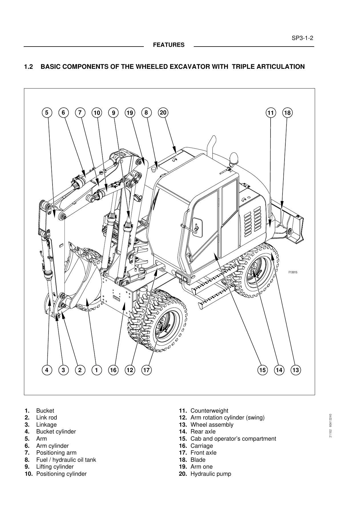
1.1 INTRODUCTIONp. 591.2 BASIC COMPONENTS OF THE WHEELED EXCAVATOR WITH TRIPLE ARTICULATIONp. 601.3 IDENTIFICATION DATAp. 61+2. TECHNICAL SPECIFICATIONp. 63
2.1 GENERAL SPECIFICATIONSp. 632.2 DIMENSIONS (mm) – TRIPLE ARTICULATION VERSIONp. 682.3 DIGGING PERFORMANCES – TRIPLE ARTICULATION VERSIONp. 692.4 DIGGING PERFORMANCES – TRIPLE ARTICULATION VERSION WITH CLAMSHELL BUCKETp. 702.5 BUCKET USEFULNESS DEPENDING ON ARMp. 712.6 LIFTING CAPACITYp. 723. FILLING CHARTp. 75+SECTION 4 SUPERSTRUCTUREp. 77
+1. SUPERSTRUCTUREp. 79
1.1 MAIN FRAME AND COUNTERWEIGHTp. 791.2 ENGINE GROUPp. 801.3 HYDRAULIC OIL RESERVOIRp. 851.4 FUEL RESERVOIRp. 881.5 COVERS AND PROTECTIONSp. 891.6 CAB GROUPp. 921.7 CAB HEATERp. 951.8 CAB ELECTRIC COMPONENTSp. 961.9 CHASSIS ELECTRIC COMPONENTSp. 981.10 SUPERSTRUCTURE MAINTENANCEp. 1051.11 SUPERSTRUCTURE HYDRAULIC SYSTEM PIPINGp. 122+1A. FLEXIBLE HOSES AND CONNECTIONSp. 133
1A.1 FLEXIBLE HOSES AND CONNECTIONSp. 133+2. HYDRAULIC PUMPSp. 145
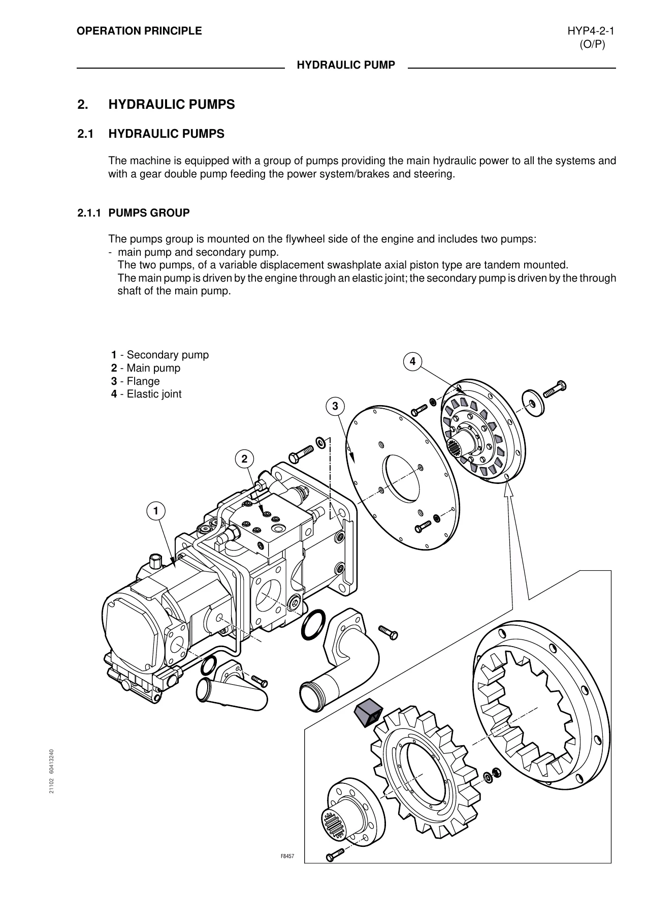
2.1 HYDRAULIC PUMPSp. 1452.2 MAIN PUMPp. 1472.3 SECONDARY PUMPp. 1542.4 GEAR DOUBLE PUMPp. 1592.1 MAIN PUMPp. 1612.2 SECONDARY PUMPp. 1852.3 GEAR DOUBLE PUMPp. 203+3. CONTROL VALVESp. 209
3.1 MAIN CONTROL VALVEp. 2093.2 ROTATION CONTROL VALVEp. 2263.1 MAIN CONTROL VALVEp. 2313.2 ROTATION CONTROL VALVEp. 234+4. SWING DEVICEp. 237
4.1 SWING DEVICEp. 2374.2 SWING HYDRAULIC MOTORp. 2394.3 SWING REDUCTION DEVICEp. 2434.1 SWING HYDRAULIC MOTORp. 2454.2 DISASSEMBLY AND ASSEMBLY OF SWING REDUCTION DEVICEp. 257+5. TRAVEL PILOT VALVEp. 273
5.1 HAND PILOT VALVEp. 2735.2 PEDALp. 277+6. CENTER JOINTp. 279
6.1 CENTER JOINTp. 2796.1 DISASSEMBLY AND ASSEMBLY OF CENTER JOINTp. 281+7. STEERING VALVEp. 283
7.1 STEERING VALVEp. 2837.1 STEERING UNIT DISASSEMBLY AND ASSEMBLYp. 287+8. BRAKE PEDAL VALVEp. 305
8.1 BRAKE PEDAL VALVEp. 3058.1 MAINTENANCEp. 3098.2 BRAKE PUMP DISASSEMBLY – ASSEMBLYp. 311+9. ACCUMULATORSp. 331
9.1 ACCUMULATORSp. 3319.1 DISASSEMBLY AND ASSEMBLY OF ACCUMULATORp. 335+10. SOLENOID VALVESp. 337
10.1 SELECTOR SOLENOID VALVESp. 33710.2 SERVICE SOLENOID VALVE GROUPp. 33910.3 STEERING TYPE CONTROL SOLENOID VALVEp. 34110.4 POWER CONTROL DISCONNECTION SOLENOID VALVE (WITH FLOW DIVIDER)p. 34210.5 SOLENOID VALVE FOR CLAMSHELL BUCKET ROTATION CONTROLp. 345+SECTION 5 UNDERCARRIAGEp. 347
+1. UNDERCARRIAGEp. 349
1.1 OUTLINESp. 3491.2 LOWER FRAMEp. 3501.3 SWING BEARINGp. 3511.4 TRAVEL UNITp. 3541.5 WHEELSp. 3551.6 BLADE ASSEMBLYp. 3671.7 LATERAL STABILIZERSp. 3681.8 HYDRAULIC HOSES AND UNDERCARRIAGE COMPONENTSp. 369+2. TRAVEL HYDRAULIC MOTORp. 379
2.1 TRAVEL HYDRAULIC MOTORp. 3792.1 DISASSEMBLY AND ASSEMBLYp. 383+3. TRANSMISSIONp. 407
3.1 TRANSMISSIONp. 4073.1 TRANSMISSION ASSEMBLY AND DISASSEMBLYp. 413+4. AXLESp. 439
4.1 REAR AXLEp. 4394.2. FRONT AXLEp. 4464.3 BRAKING UNITp. 4534.1 REAR AXLE/FRONT AXLEp. 4574.2 SPECIAL TOOLSp. 532+5. TRANSMISSION SHAFTp. 537
5. 1 TRANSMISSION SHAFTp. 5375.1 DISASSEMBLY AND ASSEMBLYp. 539+SECTION 6 FRONT-END ATTACHMENTp. 541
+1. FRONT-END ATTACHMENTp. 543
1.1 TRIPLE ARTICULATION ASSEMBLYp. 5431.2 PENETRATION ARM ASSEMBLYp. 5471.3 BUCKET ASSEMBLYp. 5501.4 FRONT PIPINGSp. 5511.5 MAINTENANCE STANDARDp. 558+2. HYDRAULIC CYLINDERSp. 581
2.1 CONSTRUCTION AND FUNCTIONp. 5812.1 CYLINDER DISASSEMBLY – ASSEMBLYp. 585+3. PINS AND BUSHINGSp. 593
3.1 SPECIFICATIONSp. 593+SECTION 7 HYDRAULIC SYSTEMp. 595
1. GENERALITIESp. 597+2. MAIN HYDRAULIC SYSTEMp. 599
2.1 GENERALITIESp. 5992.2 SUCTION CIRCUIT AND DELIVERY CIRCUITp. 6002.3 RETURN CIRCUITp. 6062.4 DRAINAGE CIRCUITp. 608+3. PILOT/BRAKES SYSTEMp. 611
3.1 GENERALITIESp. 6113.2 SUCTION CYLINDERp. 611+4. STEERING SYSTEMp. 619
4.1 GENERALITIESp. 6194.2 STEERING CIRCUITp. 620+5. BRAKES SYSTEMp. 623
5.1 GENERALITIESp. 6235.2 DESCRIPTION OF BRAKES SYSTEMp. 6235.3 OPERATION OF BRAKE PEDAL VALVEp. 625+6. OPERATION OF CIRCUITSp. 629
6.1 GENERALITIESp. 6296.2 CIRCUIT WITH CONTROLS IN NEUTRALp. 6306.3 BOOM CIRCUITp. 6326.4 DIPPER STICK CIRCUITp. 6346.5 BUCKET CIRCUITp. 6366.6 POSITIONER ARM CIRCUITp. 6386.7 TRAVEL CIRCUITp. 6406.8 ARM ANGLE CIRCUITp. 6426.9 STABILIZER/BLADE CONTROL CIRCUITp. 6446.10 HYDRAULIC HAMMER / SHRUB CUTTER CIRCUITp. 6466.11 TURRET SWING CIRCUITp. 648+7. TRAVEL CIRCUITp. 651
7.1 DESCRIPTIONp. 6517.2 TRAVEL HYDRAULIC MOTOR CONTROL CIRCUITp. 6517.3 PARKING BRAKE CONTROL CIRCUITp. 6548. HYDRAULIC SYSTEM DIAGRAMp. 656+SECTION 8 ELECTRICAL SYSTEMp. 659
+1. SAFETY RULESp. 661
1.1 SAFETY RULESp. 661+2. SPECIFICATIONS AND DATAp. 663
2.1 SPECIFICATIONS AND DATAp. 663+3. LOCATION AND FUNCTIONS OF COMPONENTSp. 665
3.1 CONSTRUCTIONp. 6653.2 LOCATION OF ELECTRICAL COMPONENTSp. 6653.3 INSTRUMENTS AND CONTROLSp. 672+4. ARRANGEMENT AND OPERATIONp. 687
4.1 ELECTRICAL SYSTEMp. 687+5. ELECTRICAL SYSTEM GENERALITIESp. 747
5.1 CONNECTIONS WITH DIODESp. 7475.2 CONNECTIONS WITH FUSE BOXp. 7485.3 CONNECTIONS WITH MINI RELAYSp. 7495.4 CONTROLLERp. 7505.5 MONITOR CONNECTIONS ON SWITCHES-INDICATORS PANELp. 7515.6 CONNECTIONS BETWEEN OPERATOR'S SEAT AND FRAMEp. 7525.7 CONNECTIONS WITH OPERATOR'S RIGHT SIDEp. 7535.8 CONNECTIONS WITH OPERATOR'S LEFT SIDEp. 7545.9 THROTTLE PISTON CONTROL ELECTRONIC UNIT (SMC)p. 7555.10 CONNECTIONS BETWEEN OPERATOR'S SEAT WIRE AND FRAME WIREp. 7565.11 CONNECTIONS WITH TEST CONNECTORp. 7575.12 CONNECTIONS WITH STEERING COLUMNp. 7585.13 ANTI-START DEVICE CONNECTIONSp. 759+6. ELECTRIC COMPONENTSp. 761
6.1 THROTTLE CONTROLp. 7616.2 CENTER JOINTp. 7626.3 BATTERIESp. 7636.4 ALTERNATORp. 7646.5 STARTERp. 766+SECTION 9 TROUBLESHOOTINGp. 775
+1. INTRODUZIONEp. 777
1.1 GENERAL INFORMATIONp. 777+2. HYDRAULIC SYSTEM TROUBLESHOOTINGp. 780
2.1 GENERALITIESp. 7802.2 FRONT ATTACHMENTp. 7842.3 SWINGp. 7902.4 TRAVELp. 7962.5 BRAKE SYSTEMp. 7982.6 STEERING SYSTEMp. 8022.7 DRIVE AXLESp. 8042.8 TRANSMISSIONp. 808+3. ELECTRICAL SYSTEM TROUBLESHOOTINGp. 811
3.1 ELECTRICAL SYSTEM COMPONENTSp. 8113.2 RELAYS AND FUSESp. 8203.3 CHECKS ON ELECTRICAL COMPONENTSp. 8233.4 CHECKS ON PILOT CONTROL SYSTEM ELECTRICAL CIRCUITp. 8263.5 BRAKE SYSTEM ELECTRICAL CHECKSp. 8283.6 TRAVEL CONTROL ELECTRICAL CIRCUITS CHECKSp. 8363.7 STABILIZERS CONTROL ELECTRICAL CIRCUIT CHECKSp. 8383.8 BLADE CONTROL ELECTRICAL CIRCUIT CHECKSp. 8423.9 POSITIONING CONTROL ELECTRICAL CIRCUIT CHECKSp. 8443.10 HAMMER CONTROL ELECTRICAL CIRCUIT CHECKSp. 8463.11 AXLE LOCK ELECTRICAL CIRCUIT CHECKSp. 8483.12 THROTTLE CONTROL ELECTRICAL CIRCUIT CHECKSp. 8503.13 DIESEL ENGINE FAILED TO START UPp. 8543.14 MONITOR FAILED TO OPERATE WITH START-UP KEY IN "ON" POSITIONp. 8563.15 STEERING CONTROLp. 8583.16 TEST HARNESSES KIT 75301702p. 870+SECTION 10 OPERATIONAL PERFORMANCE TESTp. 877
+1. INTRODUCTIONp. 879
1.1 GENERAL INFORMATION FOR TESTING OF THE MACHINEp. 879+2. PERFORMANCE STANDARDp. 881
2.1 TABLE OF EXCAVATOR PERFORMANCE STANDARDp. 8812.2 TABLE OF HYDRAULIC COMPONENTS PERFORMANCE STANDARDp. 8832.3 MAIN PUMP P-Q DIAGRAMp. 8842.4 SWING PUMP P-Q DIAGRAMp. 885+3. PREPARATION FOR PERFORMANCE TESTp. 887
3.1 INTRODUCTIONp. 887+4. EXCAVATOR PEFORMANCE TESTp. 889
4.1 ENGINE PERFORMANCE (DIESEL ENGINE SPEEDS)p. 8894.2 SWING PERFORMANCEp. 8914.3 FRONT ATTACHMENT PERFORMANCEp. 8954.4 CONTROL LEVERS / PEDAL LEVERS / BRAKE PEDALp. 8984.5 STEERINGp. 8994.6 BRAKES SYSTEMp. 900+5. HYDRAULIC COMPONENTS PERFORMANCE TESTp. 903
5.1 PILOT PRESSURE RELIEF VALVEp. 9035.2 PRESSURE RELIEF VALVESp. 9045.3 TRANSMISSION DRIVE SHAFTp. 9095.4 HYDRAULIC PUMPSp. 911+SECTION 11 ENGINEp. 915
+10. GENERAL INFORMATIONp. 919
10.1 INTRODUCTIONp. 91910.2 ENGINE VIEWp. 92010.3 ENGINE IDENTIFICATIONp. 92110.4 SAFETYp. 92210.5 ENGINE LIFT EQUIPMENTp. 92310.6 VITON SEALSp. 92410.7 RECOMMENDED CONSUMABLE PRODUCTSp. 925+11. SPECIFICATIONSp. 927
11.1 BASIC ENGINE DATAp. 92711.2 RECOMMENDED TORQUE TENSIONSp. 92911.3 COMPRESSION TEST DATAp. 933+12. CYLINDER HEAD ASSEMBLYp. 935
12.1 GENERAL DESCRIPTIONp. 93512.2 ROCKER COVERp. 93612.3 ROCKER ASSEMBLYp. 93712.4 CYLINDER HEAD ASSEMBLYp. 93912.5 VALVE SPRINGSp. 94012.6 CYLINDER HEAD ASSEMBLYp. 94212.7 VALVES AND VALVE SPRINGSp. 94812.8 VALVE GUIDESp. 95012.9 CYLINDER HEADp. 95312.10 DATA AND DIMENSIONSp. 956+13. PISTON AND CONNECTING RODp. 959
13.1 GENERAL DESCRIPTIONp. 95913.2 BIG END BEARINGp. 96113.3 PISTON AND CONNECTING RODp. 96313.4 PISTON RINGSp. 96613.5 PISTON AND CONNECTING RODp. 96713.6 PISTON AND PISTON RINGSp. 96913.7 CONNECTING RODp. 97013.8 SMALL END BUSHp. 97013.9 PISTON COOLING JETSp. 97113.10 DATA AND DIMENSIONSp. 972+14. CRANKSHAFTp. 975
14.1 GENERAL DESCRIPTIONp. 97514.2 CRANKSHAFT PULLEYp. 97614.3 REAR OIL SEAL ASSEMBLYp. 97714.4 THRUST WASHERSp. 97914.5 MAIN BEARINGSp. 98214.6 CRANKSHAFTp. 98414.7 BALANCER UNITp. 98814.8 DATA AND DIMENSIONSp. 996+15. TIMING CASE COVER AND DRIVEp. 999
15.1 GENERAL DESCRIPTIONp. 99915.2 TIMING CASE COVERp. 100015.3 FRONT OIL SEALp. 100115.4 IDLER GEAR AND HUBp. 100315.5 FUEL PUMP GEARp. 100615.6 CAMSHAFT GEARp. 100815.7 CRANKSHAFT GEARp. 100915.8 TIMING CASEp. 100915.9 CAMSHAFT AND TAPPETSp. 101115.10 DATA AND DIMENSIONSp. 1012+16. GENERAL DESCRIPTIONp. 1015
16.1 GENERAL DESCRIPTIONp. 101516.2 CYLINDER BLOCKp. 101516.3 CYLINDER LINERp. 101716.4 CYLINDER BORE, ENGINE TYPE AKp. 102316.5 DATA AND DIMENSIONSp. 1024+17. ENGINE TIMINGp. 1027
17.1 GENERAL DESCRIPTIONp. 102717.2 DATA AND DIMENSIONSp. 1032+19. LUBRICATION SYSTEMp. 1033
19.1 FILTER CANISTERp. 103319.2 FILTER HEADp. 103419.3 SUMPp. 103519.4 OIL STRAINER AND SUCTION PIPEp. 103519.5 LUBRICATING OIL PUMPp. 103619.6 RELIEF VALVEp. 104019.7 DATA AND DIMENSIONSp. 1042+20. FUEL SYSTEMp. 1043
20.1 GENERAL DESCRIPTIONp. 104320.2 FUEL FILTERSp. 104720.3 ATOMISERSp. 105020.4 FUEL LIFT PUMPp. 105220.5 LUCAS DP 200 SERIES FUEL INJECTION PUMPp. 105520.6 DATA AND DIMENSIONSp. 1061+21. COOLING SYSTEMp. 1063
21.1 GENERAL DESCRIPTIONp. 106321.2 THERMOSTATSp. 106421.3 COOLANT PUMP – EALY GEAR DRIVENp. 106521.4 FAN DRIVEp. 106821.5 DATA AND DIMENSIONSp. 1069+22. FLYWHEELp. 1071
22.1 GENERAL DESCRIPTIONp. 107122.3 RING GEARp. 107122.4 FLYWHEEL HOUSINGp. 107222.5 DATA AND DIMENSIONSp. 1073+23A. ELECTRICAL EQUIPMENTp. 1075
23A.1 GENERAL DESCRIPTIONp. 107523A.2 PRECAUTIONSp. 107523A.3 ALTERNATORp. 107723A.4 FAULT DIAGNOSISp. 107723A.5 DATA AND DIMENSIONSp. 1079+23B. ELECTRICAL EQUIPMENTp. 1081
23B.1 GENERAL DESCRIPTIONp. 108123B.2 STARTER MOTORp. 108123B.3 DATA AND DIMENSIONSp. 1083+23C. ELECTRICAL EQUIPMENTp. 1085
23C.1 GENERAL DESCRIPTIONp. 108523C.2 STARTING AIDp. 108523C.3 DATA AND DIMENSIONSp. 108725. AUXILIARY EQUIPMENTp. 1089 - Section 7 – Hydraulic System
- Main hydraulic suction, delivery, return and drainage circuits
- Pilot and brakes system
- Steering circuit
- Brake system and brake-pedal-valve operation
- Operation of hydraulic circuits
- Travel motor and parking-brake circuits
- Hydraulic system diagrams
- Section 8 – Electrical System
- Electrical safety rules and specifications
- Electrical component locations and functions
- Instruments and controls
- Electrical-system arrangement and operation
- Diodes, fuse box, relays and controller connections
- Monitor, rotating-joint and operator-control connections
- Electric components
- Section 9 – Troubleshooting
- Hydraulic-system troubleshooting
- Front-attachment, swing and travel diagnosis
- Brake, steering, drive-axle and transmission diagnosis
- Electrical components, relays and fuses
- Electrical component checks
- Pilot, brake and travel electrical-circuit checks
- Section 10 – Operational Performance Test
- Performance standards
- Preparation for performance testing
- Excavator performance tests
- Component performance tests
- Hydraulic pump and pressure checks
- Section 11 – Engine
- General information and specifications
- Cylinder head assembly
- Piston and connecting rod
- Crankshaft
- Timing case cover and drive
- Engine timing
- Lubrication and fuel systems
- Cooling system
- Flywheel and housing
- Electrical and auxiliary equipment
Together these chapters provide a system-by-system view of the EX125W and show how assemblies work before moving into the procedures needed to inspect, dismantle, repair and reinstall them. The combination of operating principles and disassembly/assembly information is particularly useful when a fault has to be traced beyond a single component rather than simply replaced by guesswork.
Hydraulic, Electrical and Diagnostic Coverage
The Fiat Kobelco EX125W workshop manual contains both hydraulic theory and practical test information. Hydraulic chapters trace the main, pilot, brake and steering circuits and describe components such as variable-displacement pumps, the main control valve, swing system, center joint and travel hydraulics. Detailed diagrams show piping relationships and circuit operation, while component repair chapters provide disassembly, inspection and assembly sequences.
Electrical coverage includes component location, instruments and controls, system arrangement, fuse and relay connections, controllers, monitor connections and individual electrical components. These sections lead into dedicated troubleshooting material for hydraulic and electrical faults. The troubleshooting section separates problems by machine function, including front attachment, swing, travel, brakes, steering, axles and transmission, helping technicians narrow a symptom to the relevant circuit or component.
The operational performance test section adds measured testing after diagnosis or repair. It includes performance standards, preparation requirements, excavator tests and component tests. Hydraulic testing material covers pump performance and pressure checks, including procedures that use pressure gauges and specified operating conditions. This makes the manual useful not only for taking components apart but also for checking whether the repaired machine or system is performing to the stated values.
IMAGES PREVIEW
Machine Specifications and Workshop Reference Data
The specification chapters give a useful baseline before service work begins. Along with the PERKINS 1004.40T engine data, the manual documents the hydraulic cylinders, drive line, controls, axles, upperstructure swing, brakes, steering, electrical system, tyres, operating weights, dimensions, digging ranges and lifting information. Triple-articulation operating weights are listed for rear-blade, rear-stabilizer and combined rear-stabilizer/front-blade configurations.
Fluid and lubricant charts provide quantities and lubricant specifications. The chart includes a 211 litre fuel tank, 21.5 litre engine cooling system, 8.5 litre engine-oil quantity and hydraulic-system filling information, along with gearbox, swing reduction and axle quantities. Workshop sections add component-specific values such as hydraulic filter data, pressure settings, tightening torques and adjustment information where required by the procedure.
Repair the EX125W with the Correct Procedures and Specifications
The Fiat Kobelco EX125W Excavator Workshop Service Repair Manual 604.13.240 – July 2002 PDF Download supports a wide range of workshop jobs, from hydraulic pump and valve work to undercarriage, axle, transmission, front attachment, electrical diagnosis, performance testing and PERKINS engine overhaul. Having the procedures, diagrams, specifications, service limits and tightening information together helps technicians diagnose faults methodically, assemble components correctly and verify repairs against the values provided for the machine.
After purchase, the manual is supplied as an instant PDF download with no physical shipping or waiting for a printed book. It can be opened on compatible computers, tablets and phones and printed when a paper reference is more convenient at the machine or workbench.

What Our Customers Say
🌟 Related Products
Discover more professional manuals for your equipment

LiuGong CLG920E CLG922E Hydraulic Excavator Service Manual 2017

Kobelco SK130-8 SK130L-8 SK140LC-8 Shop Manual S5YP0001E02 Hydraulic Excavator Workshop PDF

Hitachi ZX350LC-5B ZX350LCN-5B Service Workshop Technical Manual PDF Download


Reviews
There are no reviews yet.