
Komatsu PC1250-7, PC1250SP-7, PC1250LC-7 Hydraulic Excavator Shop Manual SEBM027301
Original price was: $44.95.$27.95Current price is: $27.95.
Comprehensive factory shop manual for Komatsu PC1250-7, PC1250SP-7, and PC1250LC-7 hydraulic excavators (Serial Numbers 20001 and up). Delivers complete engineering specifications, full hydraulic pump and valve schematics, electronic OLSS operation, undercarriage rebuild criteria, and maintenance standards.
Description
Complete Engineering Reference: Komatsu PC1250-7, PC1250SP-7, PC1250LC-7 Hydraulic Excavator Shop Manual SEBM027301
The Komatsu PC1250-7, PC1250SP-7, PC1250LC-7 Hydraulic Excavator Shop Manual SEBM027301 is the definitive technical workshop reference engineered specifically for heavy equipment technicians, master mechanics, mine maintenance teams, and rebuild facilities responsible for maintaining, troubleshooting, and overhauling 100-plus-ton Komatsu production excavators. Covering all three machine variants from serial number 20001 and up, this shop publication delivers uncompromising technical depth across primary structural systems, fluid power generation, multi-stage control valves, electronic engine interface governing, planetary drives, and complete chassis maintenance tolerances.
File Details
- Document Title: Komatsu PC1250-7, PC1250SP-7, PC1250LC-7 Shop Manual
- Document Publication Number: SEBM027301
- Publication Edition / Date: Printed in Japan 06-02 (01) / Revised July 2002
- Equipment Brand: Komatsu
- Machine Coverage: PC1250-7, PC1250SP-7, PC1250LC-7 Excavators
- Serial Number Applicability: Serial Numbers 20001 and up
- Engine Installation: Komatsu SAA6D170E-3 Turbocharged Aftercooled Diesel Engine
- Document Language: English
- Page Count: 584 Pages
- File Format: High-Resolution Digital PDF
General Machine Performance & Dimensional Specifications
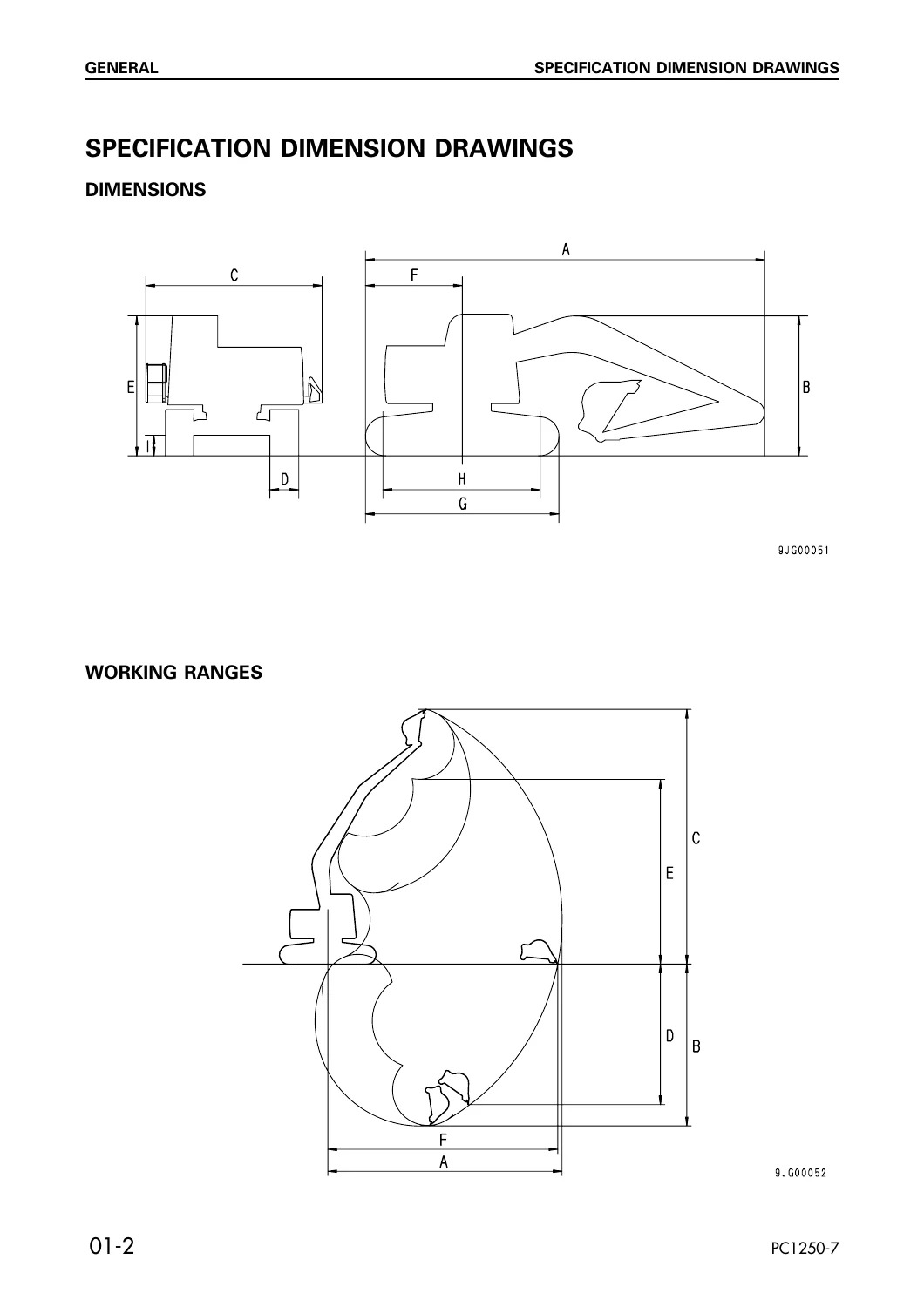
The heavy-class Komatsu PC1250-7 series represents high-production digging and loading capability, engineered across standard, super-production (SP), and long-undercarriage (LC) footprints. The Komatsu PC1250-7 excavator shop manual establishes complete engineering baselines for machine clearance, digging reach, travel speeds, and track ground contact geometry.
| Specification Metric | PC1250-7 Standard | PC1250SP-7 Super Production | PC1250LC-7 Long Carriage |
|---|---|---|---|
| Operating Weight | 105,600 kg (108,700 kg) | 109,500 kg | 112,600 kg |
| Bucket Capacity Range | 5.0 m³ standard | 6.7 m³ high-output | 5.0 m³ standard |
| Overall Transport Length | 16,020 mm | 14,790 mm | 16,020 mm |
| Overall Machine Height | 6,040 mm | 6,265 mm | 6,040 mm |
| Overall Chassis Width | 5,355 mm | 5,355 mm | 5,355 mm |
| Track Gauge / Overall Width | 3,900 mm / 4,965 mm | 3,900 mm / 4,965 mm | 3,900 mm / 5,265 mm |
| Track Shoe Width (Double Grouser) | 700 mm standard | 700 mm standard | 1,000 mm standard |
| Length of Track on Ground | 4,995 mm | 4,995 mm | 5,970 mm |
| Track Rollers (Each Side) | 8 rollers | 8 rollers | 10 rollers |
| Track Shoes (Each Side) | 48 shoes | 48 shoes | 55 shoes |
| Ground Pressure Rating | 135 kPa (1.38 kg/cm²) | 140 kPa (1.43 kg/cm²) | 85 kPa (0.87 kg/cm²) |
| Maximum Digging Reach | 15,350 mm | 14,070 mm | 15,350 mm |
| Maximum Digging Depth | 9,350 mm | 7,900 mm | 9,350 mm |
| Maximum Digging Force | 479 kN (48,800 kg) | 569 kN (58,100 kg) | 479 kN (48,800 kg) |
| Tail Swing Radius | 4,870 mm | 4,870 mm | 4,870 mm |
| Travel Speed (Low / High) | 2.1 km/h / 3.2 km/h | 2.1 km/h / 3.2 km/h | 2.7 km/h / 3.2 km/h |
Major Component Weights & Rigging Standards
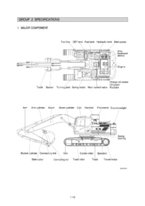
Heavy overhaul and machine transport operations require exact component weight calculations to ensure workshop safety and appropriate crane selection. This PC1250SP-7 service manual provides an exhaustive directory of assembly weights, lifting wire rope capacities, and sling angle derating charts.
| Major Sub-Assembly / Component | Unit Weight (kg) | Major Sub-Assembly / Component | Unit Weight (kg) |
|---|---|---|---|
| Complete Engine Assembly | 3,978 kg | Boom Assembly (excl. piping) | 10,380 kg (SP: 10,275 kg) |
| Bare Engine | 2,952 kg | Arm Assembly (excl. piping) | 3,520 kg (SP: 3,915 kg) |
| Counterweight Unit | 18,000 kg | Bucket Assembly (excl. piping) | 4,579 kg (SP: 6,191 kg) |
| Revolving Frame (with decks) | 10,630 kg | Boom Cylinders (Each of 2) | 1,174 kg |
| Track Frame Assembly | 28,374 kg (LC: 30,814 kg) | Arm Cylinder Assembly | 1,538 kg |
| Center Carbody Frame | 7,400 kg | Bucket Cylinders (Each of 2) | 442 kg (SP: 459 kg) |
| Track Frame (Each Side) | 4,390 kg (LC: 5,230 kg) | Swing Circle Assembly | 2,165 kg |
| Final Drive Planetary Assembly | 1,869 kg x 2 | Swing Machinery Reduction | 488 kg x 2 |
| Hydraulic Tank (dry) | 776 kg | Travel Motors (Each of 2) | 130 kg |
| No. 1 / No. 2 Main Pumps | 157 kg / 148 kg | No. 3 Main Pump Assembly | 191 kg |
| L.H. 5-Spool Control Valve | 260 kg | R.H. 4-Spool Control Valve | 253 kg |
| Swing 4-Spool Control Valve | 240 kg | Center Swivel Joint | 69 kg |
Fluid Capacities & Lubrication Directory
Maintaining lubrication integrity across extreme operating temperatures is vital to prevent mechanical seizure and hydraulic failure in 24/7 quarry and mining environments. The PC1250LC-7 excavator manual details exact reservoir volumes and oil viscosities across all machine compartments.
| Fluid Reservoir / Compartment | Fluid Type Specified | Total Specified Capacity | Refill Capacity |
|---|---|---|---|
| Fuel Reservoir Tank | Diesel Fuel (ASTM D975 No. 1 or No. 2) | 1,360 Liters | 1,360 Liters |
| Hydraulic Circuit System | Engine Oil SAE 10W / HO46-HM | 800 Liters (Tank Cap: 1,146 L) | 670 Liters (H-Level: 664 L) |
| Engine Crankcase Oil Pan | Engine Oil SAE 15W-40 / 10W-30 / 30 | 68 Liters | 55.3 Liters |
| Engine Cooling Circuit | Coolant with Antifreeze | 140 Liters | 140 Liters |
| Power Take-Off (PTO) Case | Engine Oil SAE 30 / SAE 10W | 13.5 Liters | 13.5 Liters |
| Swing Machinery Gearcase (each) | Engine Oil SAE 30 | 24.3 Liters | 24.3 Liters |
| Final Drive Planetary Casing (each) | Engine Oil SAE 30 | 22.0 Liters | 22.0 Liters |
| Swing Circle Gear & Ball Bath | Lithium Grease (G2-LI) | 65.0 Liters | 65.0 Liters |
| Front Idler Bearings (each side) | Gear Oil GO 140B / SAE 30 | 0.75 – 0.83 Liters | 0.75 – 0.83 Liters |
| Track Rollers (each roller) | Gear Oil GO 140B / SAE 30 | 0.80 – 0.85 Liters | 0.80 – 0.85 Liters |
| Carrier Rollers (each roller) | Gear Oil GO 140B / SAE 30 | 0.45 – 0.50 Liters | 0.45 – 0.50 Liters |
Hydraulic System Architecture, Variable Pumps & Valve Circuits
At the center of this excavator’s productive power is a multi-pump Open-Center Load Sensing System (OLSS) delivering unmatched flow division, high arm crowd forces, and rapid cycle times. The Komatsu PC1250-7, PC1250SP-7, PC1250LC-7 Hydraulic Excavator Shop Manual SEBM027301 thoroughly maps out pump regulation, internal servo circuits, and pilot distribution:
- Triple Swash-Plate Main Pumps: Features two HPV95+95 tandem variable-displacement axial piston pumps (No. 1 and No. 2 pumps, delivering 494 + 494 l/min) and one heavy-capacity HPV160+160 tandem variable piston pump (No. 3 pump, delivering 600 l/min). Primary working circuits operate at a standard relief pressure of 31.4 MPa (320 kg/cm²).
- Auxiliary Gear Pump Assembly: A three-stage SAR100+020+010 gear pump provides 158 l/min for PPC pilot controls at 2.9 MPa (30 kg/cm²), 33 l/min for the independent hydraulic aftercooler fan motor, and 16 l/min for pressurized PTO gear spray lubrication.
- Torque Variable Control (TVC) Valve: Modulates pump swash angle based on controller command currents reflecting engine speed fluctuations in A-mode (maximum production at 485 kW / 1,800 rpm) and E-mode (economy fuel matching at 402 kW / 1,710 rpm), or reverts to pure hydraulic load sensing in G-mode via the pump prolix switch.
- Cut-Off (CO) Valves & Cancel Function: Minimizes swash plate angles near relief pressure to curtail hydraulic heat generation and fuel loss. When high-power digging or heavy lifting is demanded, the heavy-lift solenoid valve directs pilot oil to lock the CO valve spool, allowing full flow at maximum pressure.
- Neutral Control (NC) Valves & Jet Sensors: Reads differential return pressures (Pt – Pd) across the main valve center bypass circuits, dynamically throttling pump displacement when control levers are at neutral to eliminate standby energy loss.
- Advanced Multi-Spool Control Valves: Complete breakdown of the 5-spool L.H. control valve, 4-spool R.H. control valve, and 4-spool Swing control valve, including main two-stage relief cartridges, suction check valves, port relief safety valves, and spool centering spring tensions.
- Integrated Straight-Travel Valve: Maintains pinpoint directional tracking by interconnecting the left and right travel circuits whenever front work equipment (boom, arm, or bucket) is commanded while the excavator is moving.
Swing Machinery, Final Drives & Undercarriage Maintenance Standards
Extensive rebuild tables and wear limit criteria protect driveline components from premature failure under severe pit duty. The manual specifies precise clearances and service limits for major mechanical assemblies:
| Component & Inspection Point | Standard Dimension / Clearance | Repair / Discard Limit | Corrective Remedy |
|---|---|---|---|
| Swing Gearbox Reduction Ratio | 35.716 : 1 (Double Planetary) | — | Inspect gear tooth wear |
| Swing Pinion to Swing Circle Backlash | 0 – 1.0 mm | 0.5 mm | Replace or adjust |
| Final Drive Planetary Casing (each) | 22.0 Liters | — | Replace if worn |
Reviews
There are no reviews yet.