Description
File Details
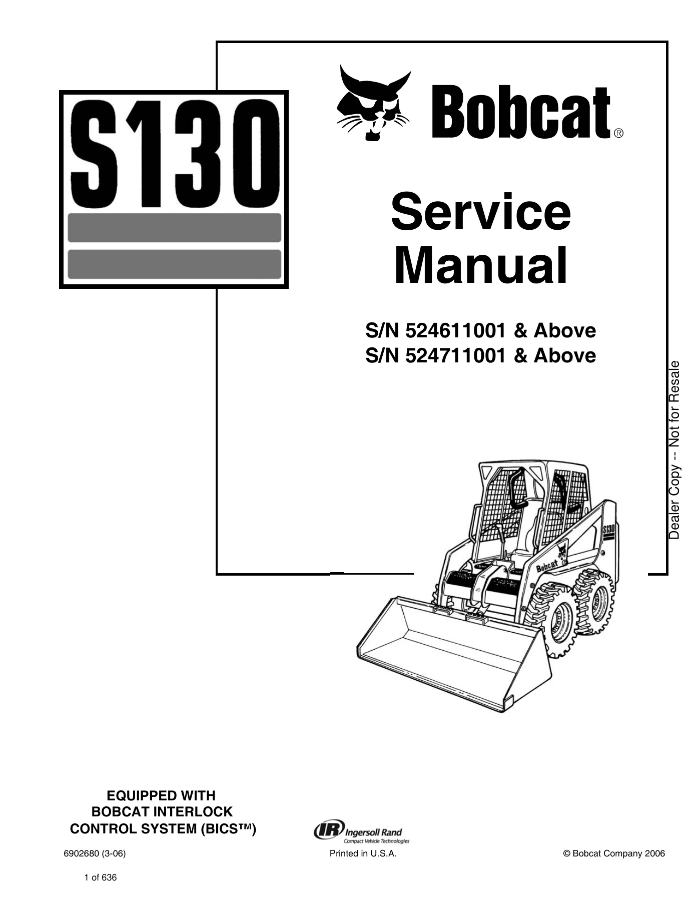
- Manual Type: Service Manual
- Brand: Bobcat (Ingersoll Rand)
- Model: S130 Skid-Steer Loader
- Serial Number Coverage: S/N 524611001 & Above, S/N 524711001 & Above
- Publication Number: 6902680 (3-06)
- Print Date: March 2006
- Language: English
- Page Count: 636 pages
- File Format: PDF
Comprehensive Workshop Information for the Bobcat S130
This Bobcat S130 Skid-Steer Loader Service Manual (S/N 524611001 & Above, 524711001 & Above) provides essential technical documentation required for mechanical maintenance, scheduled inspections, systematic troubleshooting, and total system rebuilds. Engineered specifically for professional equipment mechanics and workshop technicians, this manual covers the standard mechanical foot-control configuration as well as the Advanced Control System (ACS) and Advanced Hand Control (AHC) options. All guidance is matched directly to machines equipped with the Bobcat Interlock Control System (BICS™), ensuring that every procedure aligns with factory standards and safety requirements.
Complete PDF Bookmark Tree
Complete Bookmarks
The complete bookmarks in the “Bobcat S130 Skid-Steer Loader Service Manual (S/N 524611001 & Above, 524711001 & Above)” are as follows:
MAINTENANCE SAFETYp. 3
ALPHABETICAL INDEXp. 5
+CONTENTSp. 7
FOREWORDp. 8
+SAFETY INSTRUCTIONSp. 11
+SERIAL NUMBER LOCATIONSp. 15
Loader Serial Numberp. 15
Engine Serial Numberp. 15
DELIVERY REPORTp. 16
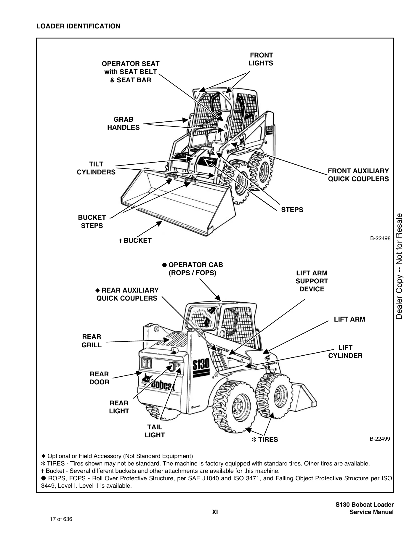
LOADER IDENTIFICATIONp. 17
+SAFETY AND MAINTENANCEp. 19
+LIFTING AND BLOCKING THE LOADERp. 21
+LIFT ARM SUPPORT DEVICEp. 23
Installing Lift Arm Support Devicep. 23
Removing The Lift Arm Support Devicep. 24
+OPERATOR CABp. 25
Descriptionp. 25
Raising The Operator Cabp. 25
Lowering The Operator Cabp. 26
Emergency Exitp. 27
+TRANSPORTING THE BOBCAT LOADERp. 29
+TOWING THE LOADERp. 31
+REMOTE STARTp. 33
+SERVICE SCHEDULEp. 37
+AIR CLEANER SERVICEp. 39
Checkingp. 39
Replacing Filter Element(s)p. 40
+ENGINE COOLING SYSTEMp. 43
Cleaning The Cooling Systemp. 43
Checking The Coolant Levelp. 44
Replacing The Coolantp. 45
+FUEL SYSTEMp. 47
Fuel Specificationsp. 47
Filling the Fuel Tankp. 47
Fuel Filterp. 48
Removing Air From The Fuel Systemp. 49
+ENGINE LUBRICATION SYSTEMp. 51
Checking Engine Oilp. 51
Engine Oil Chartp. 51
Replacing Oil And Filterp. 51
+HYDRAULIC/HYDROSTATIC SYSTEMp. 53
Checking And Adding Fluidp. 53
Hydraulic / Hydrostatic Fluid Chartp. 53
Replacing Hydraulic/Hydrostatic Filterp. 54
Replacing Hydrostatic Motor Case Drain Filter(s)p. 54
Replacing Hydraulic Fluidp. 55
Breather Capp. 56
+FINAL DRIVE TRANSMISSION (CHAINCASE)p. 57
Checking And Adding Oilp. 57
Removing The Oilp. 57
+FAN GEARBOXp. 59
Checking And Maintainingp. 59
+BOB-TACHp. 61
Inspection And Maintenancep. 61
+POWER BOB-TACHp. 63
Inspection And Maintenancep. 63
+LUBRICATION OF THE BOBCAT LOADERp. 65
+TIRE MAINTENANCEp. 69
Wheel Nutsp. 69
Rotatingp. 69
Mountingp. 69
+SPARK ARRESTOR MUFFLERp. 71
+HYDRAULIC SYSTEMp. 73
HYDRAULIC/HYDROSTATIC SCHEMATICSp. 77
+HYDRAULIC SYSTEM INFORMATIONp. 79
Glossary Of Hydraulic/Hydrostatic Symbolsp. 79
Tighten Proceduresp. 83
Troubleshooting Chartp. 84
+CYLINDER (LIFT)p. 85
Checkingp. 85
Removal And Installationp. 86
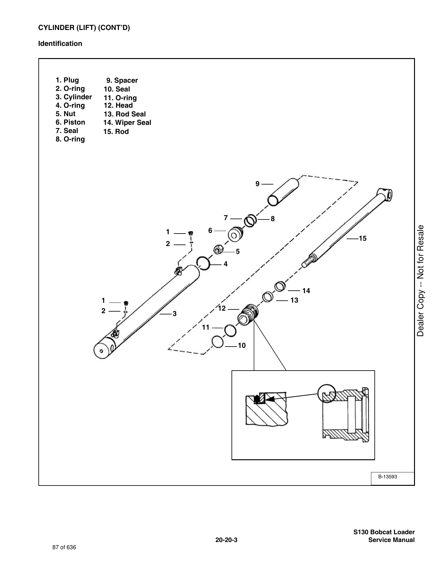
Identificationp. 87
Disassemblyp. 88
Assemblyp. 89
+CYLINDER (TILT)p. 93
Checkingp. 93
Removal And Installationp. 93
Rod End Pivot Pin Bushing And Seal Replacementp. 95
Identificationp. 96
Disassemblyp. 97
Assemblyp. 98
+CYLINDER (POWER BOB-TACH)p. 101
Checkingp. 101
Removal And Installationp. 102
Parts Identificationp. 103
Disassemblyp. 104
Assemblyp. 105
+MAIN RELIEF VALVEp. 109
Checkingp. 109
Adjustmentp. 111
Removal and Installationp. 111
+HYDRAULIC CONTROL VALVE (FOOT CONTROL)p. 113
Removal And Installationp. 113
BICS™ Valve Removal And Installationp. 118
BICS™ Valve Lift Arm By-Pass Orifice Disassembly And Assemblyp. 119
BICS™ Valve Check Valve Disassembly And Assemblyp. 120
BICS™ Valve Lock Valve Disassembly And Assemblyp. 121
BICS™ Valve Solenoid Disassembly And Assemblyp. 122
BICS™ Valve Solenoid Testingp. 123
Identification Chartp. 124
Lift Base End Restrictorp. 125
Load Check Valvesp. 125
Main Relief Valvep. 126
Port Relief Valvep. 127
Anti-Cavitation Valvep. 127
Plugp. 128
Rubber Bootp. 129
Lift And Tilt Lock Block Removal And Installationp. 130
Lift Spool and Detentp. 131
Tilt Spool Removal And Installationp. 140
Auxiliary Spool Removal And Installationp. 142
Auxiliary Electric Solenoid Disassemblyp. 142
Port-Auxiliary Section Disassemblyp. 143
Cleaning And Inspectionp. 144
+HYDRAULIC CONTROL VALVE (ADVANCED CONTROL SYSTEM) (ACS)p. 145
Descriptionp. 145
Removal And Installationp. 145
Actuator Removal And Installationp. 149
BICS™ Valve, Removal And Installationp. 150
BICS™ Valve, Lift Arm By-Pass Orifice Removal and Installationp. 151
BICS™ Valve, Check Valve Removal and Installationp. 152
BICS™ Valve, Lock Valve Removal and Installationp. 153
BICS™ Valve, Solenoid Removal and Installationp. 154
BICS™ Valve, Solenoid Testingp. 155
Identification Chart (ACS)p. 156
Lift Base End Restrictorp. 157
Load Check Valvep. 157
Main Relief Valvep. 158
Port Relief Valvep. 159
Anti-Cavitation Valve/Port Relief Valvep. 160
Anti-Cavitation Valvep. 161
Lift Spool Removal And Installationp. 162
Tilt Spool Removal And Installationp. 163
Lift And Tilt Spool Disassembly And Assemblyp. 164
Auxiliary Spool Removal And Installationp. 165
Auxiliary Electric Solenoidp. 166
Port-Auxiliary Sectionp. 167
Cleaning And Inspectionp. 167
+LIFT ARM BY-PASS CONTROL VALVEp. 169
Inspectingp. 169
Removal And Installationp. 169
Disassembly And Assemblyp. 170
+HYDRAULIC PUMPp. 171
Check The Output Of The Hydraulic Pump Without Power Bob-Tachp. 171
Check The Output Of The Hydraulic Pump With Power Bob-Tach.p. 173
Removal And Installationp. 175
Identificationp. 179
Disassembly And Assemblyp. 180
+HYDRAULIC/HYDROSTATIC FILTERp. 185
Housing Removal And Installationp. 185
+HYDRAULIC FLUID RESERVOIRp. 187
Removal And Installationp. 187
+BUCKET POSITION VALVEp. 189
Solenoid Removal And Installationp. 189
Solenoid Testingp. 189
Removal And Installationp. 190
Disassembly And Assemblyp. 191
+REAR AUXILIARY DIVERTER VALVEp. 195
Removal And Installationp. 195
Disassembly And Assemblyp. 198
Solenoid Testingp. 201
Inspectionp. 201
+POWER BOB-TACH BLOCKp. 203
Removal And Installationp. 203
Disassembly And Assemblyp. 205
+FRONT AUXILIARY HYDRAULIC COUPLER BLOCKp. 209
Removal and Installationp. 209
Disassembly And Assemblyp. 209
+HYDROSTATIC SYSTEMp. 211
+HYDROSTATIC SYSTEM INFORMATIONp. 213
Troubleshooting Chartp. 213
Replenishing Valve Functionp. 214
+HYDROSTATIC MOTORp. 215
Removal And Installationp. 215
Parts Identificationp. 217
Disassemblyp. 218
Assemblyp. 223
Carrier Shaft Seal Replacementp. 229
Carrier Removal And Installationp. 231
Carrier Parts Identificationp. 233
Carrier Disassemblyp. 234
Carrier Assemblyp. 235
+CHARGE PRESSUREp. 239
Sender Removal And Installationp. 239
Checking Charge Pressurep. 239
Adjustingp. 240
+HYDROSTATIC PUMPp. 241
Replenishing/High Pressure Relief Valvep. 241
Removal And Installationp. 242
Parts Identification (Right Half)p. 244
Parts Identification (Left Half)p. 246
Hydraulic Pump Removal And Installationp. 248
Pump Separationp. 248
Disassemblyp. 249
Assemblyp. 255
+DRIVE BELTp. 263
Shield Removal And Installationp. 263
Adjustingp. 263
Drive Belt Replacementp. 264
Tensioner Pulley Removal And Installationp. 266
Tensioner Pulley Parts Identificationp. 267
Tensioner Pulley Disassemblyp. 268
Tensioner Pulley Assemblyp. 269
+OIL COOLERp. 271
Removal and Installationp. 271
+DRIVE SYSTEMp. 273
+BRAKEp. 275
Disc Removal And Installationp. 275
Switch Operated Parking Brakep. 276
+DRIVE COMPONENTSp. 277
Axle Seal Removal And Installationp. 277
Axle Sprocket And Bearings Removal And Installationp. 279
Chain Removal And Installationp. 284
+CHAINCASEp. 287
Checking And Adding Oilp. 287
Removing The Oilp. 287
Front Cover Removal And Installationp. 288
Center Cover Removal And Installationp. 289
Rear Cover Removal And Installationp. 289
+MAIN FRAMEp. 291
+SEAT BARp. 295
Removal And Installationp. 295
Assembling Componentsp. 297
Compression Spring Disassembly And Assemblyp. 299
+OPERATOR CABp. 301
Gas Cylinder Removal And Installationp. 301
Gas Cylinder Disassemblyp. 303
Removal And Installationp. 304
+OPERATOR SEATp. 307
Removal And Installationp. 307
Seat Belt Removal And Installationp. 307
+OPERATOR SEAT (SUSPENSION)p. 309
Removal And Installationp. 309
Slide Rail Removal And Installationp. 310
Cushion Removal And Installationp. 310
Back Removal And Installationp. 311
Shock Removal And Installationp. 312
3-Point Seat Belt Removal And Installationp. 313
+BOB-TACHp. 315
Removal And Installationp. 315
Bob-Tach Lever And Wedgep. 317
Bob-Tach Stopsp. 318
+POWER BOB-TACHp. 319
Removal And Installationp. 319
Power Bob-Tach Lever And Wedgep. 321
+LIFT ARMp. 323
Removal And Installationp. 323
+REAR GRILL (S/N 524614399 & BELOW)p. 329
Gas Cylinder Removal And Installationp. 329
Removal And Installationp. 330
+REAR GRILL (S/N 524614400 & ABOVE)p. 331
Removal And Installationp. 331
+REAR DOORp. 333
Removal And Installationp. 333
Striker Removal and Installationp. 334
Striker Disassembly and Assemblyp. 334
Door Latch and Catch Adjustmentp. 334
Latch Removal And Installationp. 335
+FUEL TANKp. 337
Removal And Installationp. 337
Fuel Level Senderp. 338
+CONTROL PEDALSp. 339
Removal And Installationp. 339
Pedal Adjustmentp. 339
Crossbar Linkage Removal And Installationp. 340
Lift Foot Pedal Linkage Removal And Installationp. 341
Tilt Foot Pedal Linkage Removal And Installationp. 341
+CONTROL PEDALS (ACS)p. 343
Foot Sensor Removal And Installationp. 343
Foot Pedal Removal And Installationp. 344
Foot Pedal Linkage Disassembly And Assemblyp. 344
+CONTROL PANEL (NON-ADJUSTABLE PINTLES)p. 345
Removal and Installationp. 345
Shock Removal And Installationp. 348
Shaft Removal And Installationp. 348
Shaft Disassembly And Assemblyp. 348
Linkage Removal And Installationp. 349
Linkage Adjustmentp. 352
Linkage Neutral Adjustmentp. 355
+CONTROL PANEL (ADJUSTABLE PINTLES)p. 359
Descriptionp. 359
Removal and Installationp. 360
Shock Removal And Installationp. 363
Shaft Removal And Installationp. 363
Shaft Disassembly And Assemblyp. 364
Linkage Removal And Installationp. 365
Pintle Arm Disassembly and Assemblyp. 369
Linkage Neutral Adjustmentp. 371
Linkage Travel Adjustmentp. 375
+CONTROL HANDLEp. 379
Control Lever Removal And Installationp. 379
Control Rubber Boot Replacementp. 379
+CONTROL HANDLE (ADVANCED CONTROL SYSTEM) (ACS) SELECTABLE HAND/FOOT CONTROLp. 381
Components Identificationp. 381
Handle Sensor Removal And Installationp. 381
Control Handle Removal and Installationp. 384
Control Handle Disassembly and Assemblyp. 385
Control Lever Removal and Installationp. 385
Control Lever Bootp. 386
+ELECTRICAL SYSTEM & ANALYSISp. 387
ELECTRICAL SCHEMATICSp. 391
+ELECTRICAL SYSTEM INFORMATIONp. 395
Troubleshooting Chartp. 397
Descriptionp. 398
Relay Switch Locationp. 399
Fuse Locationp. 399
Solenoid Testp. 400
+BATTERYp. 401
Removal And Installationp. 401
Servicingp. 402
Using A Booster Battery (Jump Starting)p. 403
+ALTERNATORp. 405
Adjusting The Alternator Beltp. 405
Alternator Identificationp. 405
Charging System Checkp. 406
Alternator Voltage Testp. 407
Low Voltage Testp. 407
High Voltage Testp. 408
Removal And Installationp. 409
Rectifier Continuity (Diode) Testp. 410
Alternator Regulator Testp. 411
Disassemblyp. 411
Stator Continuity Testp. 412
Stator Ground Testp. 412
Rotor Continuity Testp. 412
Rotor Ground Testp. 412
Assemblyp. 413
+STARTERp. 415
Checkingp. 415
Removal And Installationp. 416
Parts Identificationp. 417
Disassembly and Assemblyp. 418
Inspection And Repairp. 421
No Load Testp. 423
+INSTRUMENT PANELp. 425
Left Panelp. 425
Right Panel (Standard) (With Key Switch)p. 426
Right Panel – (Deluxe) (With Keyless Start)p. 427
Option and Field Accessory Panelsp. 432
Removal And Installationp. 433
Front Accessory Panel Removal And Installationp. 434
+LIGHTSp. 435
Front Removal And Installationp. 435
Rear Removal And Installationp. 436
+BOBCAT CONTROLLERp. 437
Identification Chartp. 437
Removal And Installationp. 439
+DIAGNOSTIC SERVICE CODESp. 441
Displayp. 441
Number Codes Listp. 442
+BICS™ SYSTEMp. 445
Inspecting The BICS™ Controller (Engine STOPPED – Key ON)p. 445
Inspecting Deactivation Of The Auxiliary Hydraulics System (Engine STOPPED – Key ON)p. 445
Inspecting The Seat Bar Sensor (Engine RUNNING)p. 445
Inspecting The Traction Lock (Engine RUNNING)p. 445
Inspecting The Lift Arm By-Pass Controlp. 445
Troubleshooting Chartp. 446
Troubleshooting Guidep. 447
+SEAT BAR SENSORp. 449
Troubleshooting Chartp. 449
Testp. 450
Removal And Installationp. 451
BICS™ Circuit Testp. 452
+TRACTION LOCKp. 453
Troubleshooting Chartp. 453
Inspectingp. 454
Solenoid Removal And Installationp. 454
Guide Removalp. 456
Guide Installationp. 458
+ADVANCED CONTROL SYSTEM (ACS) SELECTABLE HAND/FOOT CONTROLp. 461
Components Identificationp. 461
Troubleshooting Guidep. 463
Controller, Connector And Wire Identificationp. 464
ACS Controller Removal And Installationp. 465
Handle Sensor Connectorp. 465
Switch Handle Removalp. 466
Switch Handle Installationp. 468
Actuators Disassembly And Assemblyp. 471
Handle Lock Solenoid Removal And Installationp. 472
Handle Lock Solenoid Disassembly And Assemblyp. 472
Handle Lock Solenoid Connectorp. 473
Calibration Of The ACS Systemp. 474
Switchable Hand/Foot Controls Calibration Procedurep. 474
Foot Sensor Disassembly And Assemblyp. 476
Foot Sensor Connectorp. 476
Foot Lock Solenoid Removal And Installationp. 477
Foot Lock Solenoid Connectorp. 477
+ELECTRICAL/HYDRAULIC CONTROLS REFERENCEp. 479
Controls Identification Chartp. 479
+FLYHWHEEL RPM SENSORp. 481
+ENGINE SERVICEp. 483
+TROUBLESHOOTINGp. 485
+ENGINE SPEED CONTROLp. 487
Removal And Installationp. 487
Disassemblyp. 487
+MUFFLERp. 489
Removal And Installationp. 489
+AIR CLEANERp. 491
Removal And Installationp. 491
+RADIATOR (S/N 524614399 & BELOW)p. 493
Removal And Installationp. 493
+RADIATOR (S/N 524614400 & ABOVE)p. 495
Removal And Installationp. 495
+COOLING FANp. 497
Drive Tension Pulley Removal And Installationp. 497
Gearbox/Blower Housing Removal And Installationp. 498
Blower Housing Grill Removal And Installationp. 500
Blower Disassembly And Assemblyp. 500
Gearbox Parts Identificationp. 502
Gearbox Disassemblyp. 503
Gearbox Assemblyp. 508
Gearbox Checking Backlashp. 512
+ENGINE COMPONENTS AND TESTINGp. 517
Compression Checkingp. 517
Glow Plugs Checkingp. 518
Glow Plugs Removal And Installationp. 518
Fuel Shut-Off Solenoid, Checkingp. 519
Fuel Shut-Off Solenoid Removal And Installationp. 520
Fuel Injection Pump Removal And Installationp. 521
Timing The Injection Pumpp. 525
Fuel Injector Removal And Installationp. 526
Checking Nozzle Injection Pressurep. 528
Nozzle Spraying Conditionp. 528
Valve Seat Tightnessp. 529
Valve Clearance Adjustmentp. 529
Valve Timing, Checkingp. 530
+ENGINEp. 531
Removal And Installationp. 531
Engine Mount Replacementp. 537
+FLYWHEEL AND HOUSINGp. 539
Flywheel Removal And Installationp. 539
Ring Gear Removal And Installationp. 539
Housing Removal And Installationp. 540
+RECONDITIONING THE ENGINEp. 543
Cylinder Head Removal And Installationp. 543
Cylinder Head Disassembly And Assemblyp. 546
Cylinder Head Servicingp. 547
Cylinder Head Top Clearancep. 547
Valve Guide Checkingp. 548
Reconditioning The Valve And Valve Seatp. 550
Valve Springp. 551
Rocker Arm And Shaft Checkingp. 552
Timing Gearcase Cover Removal And Installationp. 552
Idler Gear And Camshaft Removal And Installationp. 555
Camshaft Servicingp. 556
Idler Gear And Shaft Servicingp. 557
Timing Gears Checking Backlashp. 558
Fuel Camshaft Removal And Installationp. 558
Fuel Camshaft Governorp. 559
Crankshaft Gear Removal And Installationp. 559
Oil Pump Removal And Installationp. 560
Oil Pump Servicep. 560
Checking Engine Oil Pressurep. 561
Valve Tappetsp. 562
Piston And Connecting Rod Removal And Installationp. 562
Piston And Connecting Rod Servicingp. 564
Connecting Rod Alignmentp. 566
Crankshaft And Bearings Removal And Installationp. 567
Crankshaft And Bearings, Servicingp. 569
Cylinder Bore, Checkingp. 573
Water Pump Removal And Installationp. 573
Water Pump Disassembly And Assemblyp. 574
+HEATERp. 575
+COMPONENTSp. 577
+REGULAR MAINTENANCEp. 579
Filter Elements Removal And Installationp. 579
+BASIC TROUBLESHOOTINGp. 581
Cleaning The Heater Coilp. 581
Checking The Electrical Systemp. 582
Engine Coolant By-Passing The Heater Valvep. 586
Heater Valve Not Opening Or Closingp. 587
+SYSTEM TROUBLESHOOTING CHARTp. 589
Blower Motor Does Not Operatep. 589
Blower motor operators normally, but air flow is insufficientp. 589
+HEATER UNITp. 591
Removal And Installationp. 591
Disassembly And Assemblyp. 592
+HEATER COILp. 593
Removal And Installationp. 593
+HEATER FANp. 595
Removal And Installationp. 595
Disassembly And Assemblyp. 595
Wire Connector Removal and Installationp. 597
+HEATER VALVEp. 599
Removal and Installationp. 599
Disassembly And Assemblyp. 600
+SPECIFICATIONSp. 601
+LOADER SPECIFICATIONS (S130)p. 603
Machine Dimensionsp. 603
Performancep. 604
Controlsp. 604
Enginep. 604
Hydraulic Systemp. 605
Electricalp. 606
Drive Systemp. 606
Capacitiesp. 607
Tiresp. 607
+ENGINE SPECIFICATIONSp. 609
Fuel Injection Nozzlesp. 609
Fuel Injection Pumpp. 609
Cylinder Headp. 609
Valvesp. 609
Valve Springsp. 610
Valve Timingp. 610
Rocker Armsp. 610
Camshaftp. 610
Tappetp. 610
Cylindersp. 611
Piston Ringsp. 611
Pistonsp. 611
Connecting Rodp. 611
Oil Pumpp. 611
Crankshaftp. 612
Timing Gearp. 612
Thermostatp. 612
+TORQUE SPECIFICATIONS FOR BOLTSp. 613
Torque For General SAE Boltsp. 613
Torque For General Metric Boltsp. 614
Torque For Kubota Metric Boltsp. 614
+HYDRAULIC CONNECTION SPECIFICATIONSp. 615
O-ring Face Seal Connectionp. 615
Straight Thread O-ring Fittingp. 616
Tubelines And Hosesp. 616
Flare Fittingp. 616
O-ring Flare Fittingp. 617
Port Seal Fittingp. 619
+HYDRAULIC FLUID SPECIFICATIONSp. 621
+CONVERSIONSp. 623
Decimal And Millimeter Equivalentsp. 623
U.S. To Metric Conversionp. 623
+SMRp. 625
S130-1p. 625
S130-2p. 627
S130-3p. 629
S130-4p. 631
S130-5p. 633
S130-6p. 635
Chapters Covered
- Foreword & Safety Instructions: Post-repair inspection guidelines, safety walk-around checks, ROPS/FOPS structural rules, and fire prevention practices.
- Serial Number Identification & Delivery Report: Explanation of serial number module combinations, engine serial placement, and delivery checklist forms.
- Loader Identification: Component nomenclature, cab controls, grab handles, lift arm configurations, quick couplers, and attachment interfaces.
- Safety & Maintenance (Section 10-01): Scheduled servicing charts, air cleaner double-element replacement, Bob-Tach wedge inspection, Power Bob-Tach maintenance, engine cooling system flushing, engine oil viscosity guidelines, fan gearbox lubrication, chaincase fluid changes, fuel system air purging, hydraulic reservoir filter renewals, lift arm support device operation, cab tilt procedures, remote start tool (MEL1563) hookup, spark arrestor muffler servicing, tire rotation, wheel nut torquing, towing precautions, and machine transport tie-down.
- Hydraulic System (Section 20-01): Hydraulic schematic diagrams and symbol glossary; bucket position valve service and solenoid testing; lift cylinder, tilt cylinder, and Power Bob-Tach cylinder overhaul; front auxiliary hydraulic coupler block rebuilding; standard foot-control hydraulic control valve overhaul (spool teardown, detent assembly, centering springs, load checks, port reliefs, and anti-cavitation valves); Advanced Control System (ACS) control valve and electric actuator linkage; hydraulic reservoir removal; hydraulic/hydrostatic filter base; gear-type hydraulic pump testing, removal, and bench overhaul; lift arm by-pass control valve; main relief valve calibration; Power Bob-Tach manifold; rear auxiliary diverter valve; and hydraulic troubleshooting charts.
- Hydrostatic System (Section 30-01): Hydrostatic flow schematics, charge pressure verification and shim-pack adjustment, drive belt tensioner alignment, drive belt replacement, hydrostatic motor bench overhaul (geroler assembly, shuttle spool, and low-pressure relief valve), motor carrier bearing pre-load, axle shaft seal replacement, tandem variable-displacement hydrostatic pump separation, rotating group servicing, swashplates, trunnion bearings, replenishing/high-pressure relief valves, and oil cooler removal.
- Drive System (Section 40-01): Parking brake disc replacement, electric traction lock guide servicing, final drive chaincase fluid draining, cover plate removal, axle hub puller operation, outer axle seal installation, axle bearing pressing, and drive chain replacement.
- Main Frame (Section 50-01): Operator cab (ROPS/FOPS Level I & II) mounting hardware, emergency exit window cord procedures, operator seat and suspension seat adjustments, seat bar sensors, fuel tank extraction, rear door and rear grill alignment, lift arm assembly, and Bob-Tach framework.
- Electrical System & Analysis (Section 60-01): Battery service, starter motor and alternator circuits, instrument panel wiring, BICS™ interlock controller diagnostic troubleshooting, ACS and AHC actuator calibration, fuse panels, electrical schematics, lighting, and sensor testing.
- Engine Service (Section 70-01): Engine specifications, complete engine assembly removal and installation, governor and speed control linkages, cooling fan, radiator maintenance, flywheel and housing, engine reconditioning procedures, and engine troubleshooting.
- Heater (Section 80-01): Heater core and coil service, blower fan motor, coolant valve operation, seasonal duct filter replacement, and heating system diagnostics.
- Specifications (Section SPEC-01): Machine operational ratings, fluid capacities, hydraulic connection torque standards, bolt tightening torque charts, and hydraulic fluid viscosity recommendations.
Together, these chapters give service personnel an exhaustive reference spanning every mechanical, hydraulic, and electrical assembly on the machine. Rather than relying on guesswork, mechanics have immediate access to manufacturer-specified assembly clearances, critical pressure settings, tightening sequences, and diagnostic charts.
Hydraulic & Hydrostatic System Teardown & Calibration
Working on the Bobcat S130 Skid-Steer Loader demands precise attention to fluid power circuits. The hydraulic chapter outlines exact methods for testing gear pump delivery under load, establishing baseline flow against system relief pressures of 2500–2700 PSI (17237–18615 kPa). Detailed sections guide you through rebuilding the main hydraulic control valve, whether equipped with manual foot linkages or the electronic Advanced Control System (ACS). Step-by-step procedures outline the extraction of load check valves, port relief valves, anti-cavitation assemblies, and the BICS™ valve manifold, complete with torque sequences from 110–130 in-lb through 190–210 in-lb to ensure uniform sealing.
For hydraulic cylinders, the manual provides full exploded views and instructions for repacking lift cylinders, tilt cylinders, and Power Bob-Tach cylinders using specialized seal tools, including spanner wrench torque specifications of 600 ft-lb for lift cylinder piston nuts and 100 ft-lb plus 135-degree rotation for tilt cylinder nuts. On the hydrostatic drive side, technicians can accurately diagnose drive lag, motor creep, or overheating using detailed pressure testing procedures. Charge pressure adjustment instructions detail shim-pack thickness adjustments (where a 0.010 inch shim alters pressure by 8 PSI) to hit the required 220–270 PSI at high idle. Complete teardown sequences for the variable-displacement piston pumps and geroler hydrostatic motors allow for inspection of valve plates, slipper guides, pistons, swashplates, and the 5000 PSI high-pressure relief cartridges.
Drive Train, Axles & Chassis Mechanicals
This Bobcat S130 service manual covers the entire final drive train housed within the central chaincase. It provides explicit directions for removing the front, center, and rear access covers to inspect the continuous drive chains, drive sprockets, and parking brake discs. When servicing axle hubs, the manual specifies puller setups and warns against misalignment during separation from the tapered axle shafts. Clear instructions dictate hub bolt tightening to 725–800 ft-lb and sprocket mounting bolts to 300–330 ft-lb. Axle seal renewal is outlined using dedicated seal driver tools (MEL1399) to seat the seal flush with the axle tube, preventing chaincase contamination and oil loss. Motor carrier removal, bearing pre-load adjustments, and dial indicator end-play checks (ensuring end play does not exceed 0.007 inch) are covered in full detail.
Electrical Diagnostics, BICS™ & Machine Maintenance
Electrical troubleshooting is simplified through comprehensive wire harness routing, connector pinouts, and logic charts for the Bobcat Interlock Control System (BICS™). Technicians can test safety interlock switches, seat bar sensors, traction lock solenoids, and auxiliary control coils (7.7 ohms for standard lock coils, 9.7 ohms for BICS and bucket position coils). The preventative maintenance section provides an easy-to-follow maintenance matrix spanning daily 8–10 hour checks through 50, 100, 250, 500, and 1000-hour milestones. Detailed procedures cover draining and refilling the cooling system using propylene glycol (purple) premix at a 47/53 ratio for -34°F freeze protection, adjusting alternator belt tension, servicing the fan drive gearbox with SAE 90W gear lubricant, and cleaning the internal spark arrestor chamber to maintain safety compliance.
Professional Capability & Instant Delivery
Equipped with this comprehensive Bobcat S130 Skid-Steer Loader Service Manual (S/N 524611001 & Above, 524711001 & Above), owners, fleet managers, and independent repair shops gain full technical autonomy. You can execute routine fluid changes, calibrate complex hydraulic valves, trace electrical faults to individual connectors, or perform complete engine and transmission overhauls with complete confidence. Having verified factory specifications and step-by-step procedures prevents expensive diagnostic errors, eliminates equipment downtime, and protects your machinery investment. This digital manual is delivered immediately as an instant PDF download upon purchase. With no physical shipping required, you can view the entire document immediately on your desktop computer, field tablet, or mobile phone, or print out clean, high-resolution pages directly for the shop floor.


Reviews
There are no reviews yet.