Description
Professional Workshop Service Manual for Bobcat S450 Skid-Steer Loaders
The Bobcat S450 Skid-Steer Loader Service Manual (S/N AV9V11001 & Above, B1E611001 & Above) – 6990808enUS provides heavy equipment technicians, independent repair shops, and fleet owners with exhaustive workshop procedures for maintaining, inspecting, troubleshooting, and overhauling the Bobcat S450 loader. Spanning 994 comprehensive pages, this official publication (publication number 6990808enUS, revised March 2018) delivers complete factory specifications, step-by-step disassembly and assembly instructions, component identification callouts, and multi-system diagnostic flows required to keep your machine operating at peak factory productivity.
File Details
- Document Type: Factory Service Manual (Shop / Repair Manual)
- Machine Model: Bobcat S450 Skid-Steer Loader
- Publication Number: 6990808enUS (03-18) (E)
- Publication Date: March 2018
- Serial Number Coverage: S/N AV9V11001 & Above, S/N B1E611001 & Above (including intermediate series updates)
- Language: English (enUS)
- Total Page Count: 994 Pages
- File Format: Digital PDF
Chapters Covered
- Safety and Maintenance: Lifting and blocking procedures, lift arm support device installation and removal, operator cab tilting and securing, cab door sensor logic, trailer transport fastening, towing limitations, remote start service tool operation (MEL1563 and 7217666 kits), comprehensive preventative maintenance schedules, air cleaner servicing, engine cooling system draining, flushing, and filling, fuel delivery standards and B5 biodiesel precautions, engine oil viscosity guidelines and filter replacement, hydraulic/hydrostatic fluid changing and filter service, chaincase maintenance, Bob-Tach wedge inspection, machine greasing locations, tire and wheel nut torquing, spark arrester cleaning, and machine storage procedures.
- Hydraulic System: Full hydraulic/hydrostatic schematic diagrams (manual controls, Selectable Joystick Controls / SJC, Advanced Control System / ACS, and all factory option configurations), hydraulic symbol glossary, system troubleshooting charts, lift cylinder and tilt cylinder testing, removal, teardown, inspection, and rebuild (including standard and AZNB11488 & Above cushioned configurations), Power Bob-Tach cylinder overhaul, main relief valve testing and setting, standard and joystick hydraulic control valve rebuilding, spool detent and centering spring maintenance, BICS lock valve testing, lift arm bypass control valve servicing, gear pump flow and pressure testing, reservoir screen cleaning, and auxiliary coupler block servicing.
- Hydrostatic System: Drive circuit diagnostics, tandem hydrostatic pump testing, drive motor operation, high-pressure relief valve settings, charge pressure checks, and servo piston swashplate adjustments.
- Drive System: Final drive transmission chaincase, axle bearings, sprocket inspection, and drive chain adjustment.
- Mainframe: ROPS/FOPS operator cab structure, lift arm assembly, pivot pin inspection, operator seat and seat bar linkage, and rear door/grille servicing.
- Electrical System and Analysis: Circuit schematics, alternator charging diagnostics, harness routing, solenoid coil resistance testing, Bobcat Interlock Control System (BICS) controller troubleshooting, and instrument display diagnostic trouble codes.
- Engine Service: Engine mechanical servicing, fuel injection components, air intake, glow plug starting circuit, and cooling system maintenance.
- Heating, Ventilation and Air Conditioning (HVAC): Air conditioning condenser maintenance, heater core and evaporator servicing, blower fan diagnostics, and plenum drainage.
- Specifications: Factory fluid capacities, machine working dimensions, pressure ratings, flow rates, and fastner torque specifications.
- Alphabetical Index: Rapid-access technical subject lookup.
Together, these technical chapters provide the professional mechanic with the complete engineering groundwork necessary to diagnose subtle hydraulic drops, track down elusive electrical faults, perform precision mechanical alignments, and complete complete structural teardowns on the Bobcat S450 Skid-Steer Loader with total factory confidence.
Complete PDF Bookmark Tree
Complete Bookmarks
The complete bookmarks in the “Bobcat S450 Skid-Steer Loader Service Manual (S/N AV9V11001 & Above, B1E611001 & Above) – 6990808enUS” are as follows:
MAINTENANCE SAFETYp. 3
CONTENTSp. 5
+FOREWORDp. 7
FOREWORDp. 9
+SAFETY INSTRUCTIONSp. 11
+FIRE PREVENTIONp. 12
Maintenancep. 12
Operationp. 12
Electricalp. 12
Hydraulic Systemp. 12
Fuelingp. 12
Startingp. 12
Spark Arrester Exhaust Systemp. 12
Welding And Grindingp. 13
Fire Extinguishersp. 13
+SERIAL NUMBER LOCATIONSp. 14
Loader Serial Numberp. 14
Engine Serial Numberp. 14
DELIVERY REPORTp. 15
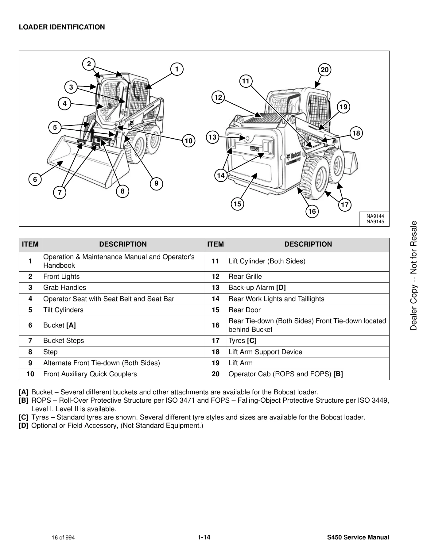
LOADER IDENTIFICATIONp. 16
+SAFETY AND MAINTENANCEp. 17
+LIFTING AND BLOCKING THE LOADERp. 21
+LIFT ARM SUPPORT DEVICEp. 23
Descriptionp. 23
Installingp. 24
Removingp. 25
+OPERATOR CABp. 27
Descriptionp. 27
Cab Door Sensorp. 27
Raisingp. 28
Loweringp. 30
+TRANSPORTING THE LOADER ON A TRAILERp. 31
Loading And Unloadingp. 31
Fasteningp. 31
+TOWING THE LOADERp. 33
+REMOTE START TOOL KIT – MEL1563p. 35
Remote Start Tool – MEL1563p. 35
Service Tool Harness Communicator – MEL1566p. 37
Remote Start Procedurep. 37
+REMOTE START TOOL (SERVICE TOOL) KIT – 7217666p. 41
Descriptionp. 41
Remote Start Tool (Service Tool) – 7022042p. 42
Loader Service Tool Harness – 6689747p. 43
Computer Service Tool Harness – 6689746p. 44
Remote Start Procedurep. 45
+SERVICE SCHEDULEp. 49
Maintenance Intervalsp. 49
+ENGINE AIR CLEANERp. 51
+ENGINE COOLING SYSTEMp. 53
Maintenance Platformp. 53
Cleaningp. 53
Checking And Adding Coolantp. 56
Removing And Replacing Coolantp. 57
+FUEL SYSTEMp. 59
Fuel Specificationsp. 59
Biodiesel Blend Fuelp. 59
Filling The Fuel Tankp. 60
Fuel Filtersp. 61
Removing Air From The Fuel Systemp. 63
+ENGINE LUBRICATION SYSTEMp. 65
Checking And Adding Engine Oilp. 65
Engine Oil Chartp. 65
Removing And Replacing Oil And Filterp. 66
+HYDRAULIC / HYDROSTATIC SYSTEMp. 69
Checking And Adding Fluidp. 69
Hydraulic / Hydrostatic Fluid Chartp. 69
Removing And Replacing Hydraulic Fluidp. 70
Removing And Replacing Hydraulic / Hydrostatic Filterp. 73
Removing And Replacing Hydraulic Charge Filterp. 74
Replacing Reservoir Breather Capp. 76
+FINAL DRIVE TRANSMISSION (CHAINCASE)p. 77
Checking And Adding Fluidp. 77
Removing And Replacing Fluidp. 77
+BOB-TACH (HAND LEVER)p. 79
Inspection And Maintenancep. 79
+BOB-TACH (POWER)p. 81
Inspection And Maintenancep. 81
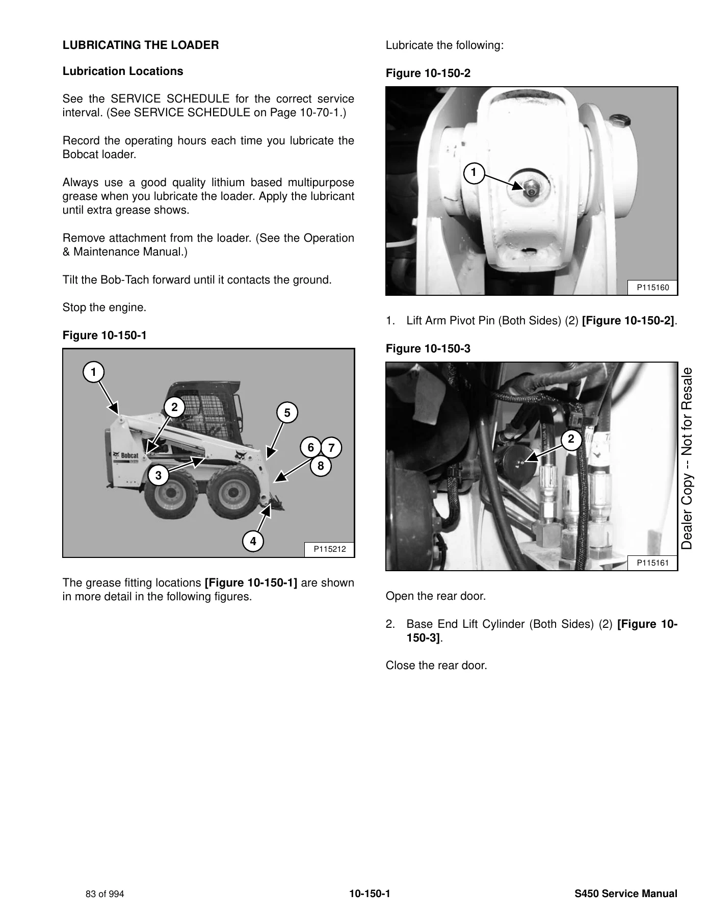
+LUBRICATING THE LOADERp. 83
Lubrication Locationsp. 83
+TIRE MAINTENANCEp. 87
Wheel Nutsp. 87
Rotatingp. 87
Mountingp. 88
+SPARK ARRESTER MUFFLERp. 89
+PIVOT PINSp. 91
Inspection And Maintenancep. 91
+LOADER STORAGE AND RETURN TO SERVICEp. 93
Storagep. 93
Return To Servicep. 93
+STOPPING THE ENGINE AND LEAVING THE LOADERp. 95
+EMERGENCY EXITp. 97
Rear Window Identificationp. 97
Rear Window Removal (Latches)p. 97
Rear Window Removal (Rubber Cord)p. 97
External Access (Rear Window With Latches)p. 98
External Access (Rear Window With Rubber Cord)p. 98
Front Doorp. 99
+SEAT BELTp. 101
Inspection And Maintenancep. 101
+HYDRAULIC SYSTEMp. 103
HYDRAULIC / HYDROSTATIC SCHEMATICSp. 107
+HYDRAULIC SYSTEM INFORMATIONp. 123
Glossary Of Hydraulic / Hydrostatic Symbolsp. 123
Troubleshootingp. 127
+CYLINDER (LIFT)p. 129
Testingp. 129
Removal And Installationp. 130
Parts Identificationp. 132
Disassemblyp. 133
Assemblyp. 135
+CYLINDER (TILT)p. 139
Testingp. 139
Removal And Installationp. 140
Base End Pivot Pin Removal And Installationp. 141
Parts Identificationp. 142
Disassemblyp. 143
Assemblyp. 145
+CYLINDER (LIFT) (AZNB11488 & ABOVE)p. 149
Parts Identificationp. 149
Disassemblyp. 150
Assemblyp. 152
+CYLINDER (TILT) (AZNB11488 & ABOVE)p. 157
Parts Identificationp. 157
Disassemblyp. 158
Assemblyp. 160
+CYLINDER (BOB-TACH)p. 165
Testingp. 165
Removal And Installationp. 166
Parts Identificationp. 167
Disassemblyp. 168
Assemblyp. 170
+MAIN RELIEF VALVEp. 173
Descriptionp. 173
Testingp. 174
Adjustingp. 176
Removal And Installationp. 177
+HYDRAULIC CONTROL VALVE (STANDARD)p. 179
Descriptionp. 179
Removal And Installationp. 180
Mount Bracket Removal And Installationp. 183
Identification Chartp. 184
Lift Load Check Valve Removal And Installationp. 185
Load Check Valve Removal And Installation (Tilt And Auxiliary)p. 186
Anti-Cavitation Valve Removal And Installation (Lift, Rod End)p. 187
Port Relief / Anti-Cavitation Valve Removal And Installation (Lift, Base End)p. 187
Port Relief / Anti-Cavitation Valve Removal And Installation (Tilt, Base End)p. 188
Port Relief / Anti-Cavitation Valve Removal And Installation (Tilt, Rod End)p. 188
Port Relief Valve Removal And Installationp. 189
Plug Removal And Installationp. 191
Rubber Boot Removal And Installationp. 192
End Cap Block Removal And Installationp. 192
Lift Spool And Detent Removal And Installationp. 193
Tilt Spool Removal And Installationp. 201
Auxiliary Spool Removal And Installationp. 203
Auxiliary Solenoid Removal And Installationp. 204
Solenoid Removal And Installationp. 205
Lock Valve Removal And Installationp. 206
Lift Arm Bypass Orifice Removal And Installationp. 208
Main Relief Valve Removal And Installationp. 208
Check Valve Removal And Installationp. 209
+HYDRAULIC CONTROL VALVE (ACS) OR (SJC)p. 211
Descriptionp. 211
Removal And Installationp. 211
Actuator Removal And Installation (In Loader)p. 214
Actuator Removal And Installation (Out Of Loader)p. 216
Identification Chartp. 219
Mount Bracket Removal And Installationp. 220
Lift Load Check Valve Removal And Installationp. 220
Load Check Valve Removal And Installation (Tilt And Auxiliary)p. 221
Anti-Cavitation Valve Removal And Installation (Lift, Rod End)p. 222
Port Relief / Anti-Cavitation Valve Removal And Installation (Lift, Base End)p. 222
Port Relief / Anti-Cavitation Valve Removal And Installation (Tilt, Base End)p. 223
Port Relief / Anti-Cavitation Valve Removal And Installation (Tilt, Rod End)p. 223
Port Relief Valve Removal And Installationp. 224
Plug Removal And Installationp. 226
End Cap Block Removal And Installationp. 227
Lift Spool Removal And Installationp. 227
Lift Spool Disassembly And Assemblyp. 229
Tilt Spool Removal And Installationp. 230
Auxiliary Spool Removal And Installationp. 232
Auxiliary Solenoid Removal And Installationp. 233
Solenoid Removal And Installationp. 234
Lock Valve Removal And Installationp. 235
Lift Arm Bypass Orifice Removal And Installationp. 237
Main Relief Valve Removal And Installationp. 237
Check Valve Removal And Installationp. 238
+LIFT ARM BYPASS CONTROL VALVEp. 239
Descriptionp. 239
Testingp. 239
Removal And Installationp. 240
Bracket Removal And Installationp. 241
Disassembly And Assemblyp. 241
+HYDRAULIC PUMPp. 243
Descriptionp. 243
Pump Test At Quick Couplersp. 244
Direct Pump Test (Standard Section)p. 246
Direct Pump Test (Charge Section)p. 248
Removal And Installationp. 250
Hydraulic Pump Startupp. 252
Parts Identificationp. 253
Disassembly And Assemblyp. 254
+HYDRAULIC / HYDROSTATIC FILTERSp. 255
Descriptionp. 255
Housing Removal And Installationp. 255
+HYDRAULIC FLUID RESERVOIRp. 257
Descriptionp. 257
Removal And Installationp. 257
Hydraulic Fluid Screenp. 258
Gauge Removal And Installationp. 258
+OIL COOLERp. 259
Removal And Installationp. 259
+BUCKET POSITION VALVEp. 261
Descriptionp. 261
Solenoid Removal And Installationp. 261
Solenoid Testingp. 262
Removal And Installationp. 262
Disassembly And Assemblyp. 264
+BOB-TACH (POWER) BLOCK (EARLIER MODELS)p. 265
Descriptionp. 265
Removal And Installationp. 265
Disassembly And Assemblyp. 267
+BOB-TACH (POWER) BLOCK (LATER MODELS)p. 275
Descriptionp. 275
Testing Relief Valvep. 275
Removal And Installationp. 277
Disassembly And Assemblyp. 279
+FRONT AUXILIARY HYDRAULIC COUPLER BLOCKp. 285
Descriptionp. 285
Removal And Installationp. 286
Disassembly And Assembly (FFI/FI)p. 287
Disassembly And Assembly (FFH/FH)p. 289
+HYDROSTATIC SYSTEMp. 291
+HYDROSTATIC SYSTEM INFORMATIONp. 293
Descriptionp. 293
Troubleshootingp. 294
+HYDROSTATIC DRIVE MOTORp. 295
Descriptionp. 295
Removal And Installationp. 295
Parts Identificationp. 297
Disassembly And Assemblyp. 298
Shaft Seal Replacementp. 304
+CHARGE PRESSUREp. 305
Descriptionp. 305
Testingp. 305
Adjustingp. 307
Sender Removal And Installationp. 309
+HYDROSTATIC PUMPp. 311
Descriptionp. 311
Removal And Installationp. 312
Hydrostatic Pump Startupp. 313
Replenishing / High Pressure Relief Valve Removal And Installationp. 314
Parts Identification (Left Half)p. 315
Parts Identification (Right Half)p. 316
Disassemblyp. 317
Assemblyp. 324
+HYDROSTATIC PUMP (SJC)p. 331
Descriptionp. 331
Hydraulic Controller Removal And Installationp. 332
Removal And Installationp. 334
Hydrostatic Pump Startupp. 335
Parts Identificationp. 336
High Pressure Relief And Bypass Valvep. 337
Charge Relief Valvep. 338
Disassembly And Assemblyp. 339
Mechanical Neutral Adjustmentp. 352
Hydraulic Controller Neutral Adjustmentp. 354
+DRIVE BELTp. 359
Belt Adjustmentp. 359
Belt Replacementp. 359
Tensioner Pulley Removal And Installationp. 361
Tensioner Pulley Disassembly And Assemblyp. 363
+DRAIN MANIFOLDp. 365
Descriptionp. 365
Drain Manifold Removal And Installationp. 365
+DRIVE SYSTEMp. 367
+BRAKEp. 369
Descriptionp. 369
Disc Removal And Installationp. 369
+DRIVE COMPONENTSp. 371
Descriptionp. 371
Axle Seal Removal And Installationp. 372
Axle, Sprocket And Bearings Removal And Installationp. 374
Chain Removal And Installationp. 378
+CHAINCASEp. 381
Descriptionp. 381
Front Cover Removal And Installationp. 381
Center Cover Removal And Installationp. 382
+MAINFRAMEp. 383
+SEAT BARp. 387
Descriptionp. 387
Removal And Installationp. 387
Disassembly And Assemblyp. 388
Compression Spring Disassembly And Assemblyp. 389
+OPERATOR CABp. 391
Gas Spring Removal And Installationp. 391
Gas Spring Bracket Disassembly And Assemblyp. 392
Removal And Installationp. 392
+OPERATOR SEATp. 395
Removal And Installationp. 395
Seat Belt Removal And Installation (Retractable)p. 395
Seat Belt And Bracket Removal And Installation (Standard)p. 396
Seat Belt Bracket Removal And Installationp. 396
+OPERATOR SEAT (SUSPENSION)p. 397
Removal And Installationp. 397
Slide Rail Removal And Installationp. 397
Seat Belt Removal And Installationp. 398
Lower Cushion Removalp. 398
Lower Cushion Installationp. 399
Back Cushion Removal And Installationp. 399
Shock Removal And Installationp. 400
3-Point Seat Belt Removal And Installationp. 400
+BOB-TACH (HAND LEVER)p. 403
Descriptionp. 403
Removal And Installationp. 403
Lever And Wedge Disassembly And Assemblyp. 405
Pivot Pin Bushing And Seal Removal And Installationp. 407
+BOB-TACH (POWER)p. 409
Descriptionp. 409
Removal And Installationp. 409
Lever And Wedge Disassembly And Assemblyp. 411
Pivot Pin Bushing And Seal Removal And Installationp. 414
+LIFT ARMSp. 415
Removal And Installationp. 415
+REAR GRILLEp. 419
Removingp. 419
Installingp. 419
+REAR DOOR (TAILGATE)p. 421
Removal And Installationp. 421
Striker Removal And Installationp. 422
Striker Disassembly And Assemblyp. 422
Striker Adjustingp. 423
Latch Removal And Installationp. 423
+FUEL TANKp. 425
Removal And Installationp. 425
Fuel Fill Screen Removal And Installationp. 427
Fuel Level Sender Removal And Installationp. 427
+CONTROL PEDALS AND LINKAGESp. 429
Descriptionp. 429
Pedal Removal And Installationp. 429
Linkage Removal And Installationp. 430
Pedal (Adjusting)p. 431
Floor Pan Removal And Installationp. 432
+CONTROL PEDALS AND LINKAGES (ACS)p. 433
Descriptionp. 433
Pedal Removal And Installationp. 433
Linkage Removal And Installationp. 434
Pedal (Adjusting)p. 434
Floor Pan Removal And Installationp. 435
+CONTROL PEDALS AND LINKAGES (SJC)p. 437
+CONTROL PANELp. 439
Descriptionp. 439
Removal And Installationp. 440
Disassembly And Assemblyp. 441
Linkage Removal And Installationp. 443
Pintle Arm Disassembly And Assemblyp. 447
Linkage Neutral (Adjusting)p. 448
Linkage Travel (Adjusting)p. 452
Shock Removal And Installationp. 456
+CONTROL PANEL (SJC)p. 457
Descriptionp. 457
Removal And Installationp. 457
+CONTROL HANDLE / LEVERp. 459
Descriptionp. 459
Lever Removal And Installationp. 459
Boot Removal And Installationp. 460
+CONTROL HANDLE / LEVER (ACS)p. 461
Descriptionp. 461
Handle Sensor Removal And Installationp. 461
Handle Removal And Installationp. 464
Handle Disassembly And Assemblyp. 465
Lever Removal And Installationp. 465
Boot Removal And Installationp. 466
+CONTROL HANDLE / LEVER (SJC)p. 467
Descriptionp. 467
Joystick Testingp. 467
Joystick Removal And Installationp. 468
+WINDOW (REAR)p. 469
Rear Window Identificationp. 469
Removal (Rubber Cord)p. 469
Installation (Rubber Cord)p. 470
Removal And Installation (Latches)p. 472
Disassembly And Assembly (Latches)p. 472
+WINDOW (TOP)p. 473
Removal And Installationp. 473
+WINDOW (SIDE)p. 475
Removal And Installationp. 475
+CAB DOORp. 477
Descriptionp. 477
Removal And Installationp. 477
Disassembly And Assemblyp. 478
Aligningp. 479
Adjustingp. 480
Checking Operationp. 480
+ARMRESTp. 481
Descriptionp. 481
Removal And Installationp. 482
Disassembly And Assemblyp. 483
+LEFT SIDE LOWER PANELp. 485
Removal And Installationp. 485
Disassembly And Assemblyp. 487
+RIGHT SIDE LOWER PANELp. 489
Removal And Installationp. 489
Disassembly And Assemblyp. 490
+HEADLINERp. 493
Removal And Installationp. 493
+ELECTRICAL SYSTEM AND ANALYSISp. 495
ELECTRICAL SCHEMATICSp. 501
+ELECTRICAL SYSTEM INFORMATIONp. 627
Glossary Of Electrical Symbolsp. 627
Standard Cab Harness Connectorsp. 630
Deluxe Cab Harness Connectorsp. 631
Mainframe / Engine Harness Connectors – Manual Controls (Earlier Models)p. 632
Mainframe / Engine Harness Connectors – SJC/ACS Controls (Earlier Models)p. 633
Mainframe / Engine Harness Connectors – Manual Controls (Later Models)p. 634
Mainframe / Engine Harness Connectors – SJC/ACS Controls (Later Models)p. 635
Descriptionp. 636
Fuse And Relay Location / Identificationp. 636
Troubleshootingp. 640
Solenoid Testingp. 641
+BATTERYp. 643
Servicingp. 643
Maintaining Battery Charge Levelp. 643
Battery Service During Machine Storagep. 643
Battery Testingp. 644
Battery Chargingp. 644
Using A Booster Battery (Jump Starting)p. 645
Removal And Installationp. 646
+ALTERNATORp. 651
Belt Adjustmentp. 651
Belt Replacementp. 651
Charging System Inspectionp. 652
Alternator Voltage Testingp. 653
Low Voltage Testingp. 653
High Voltage Testingp. 654
Removal And Installationp. 655
Parts Identificationp. 656
+STARTERp. 657
Testingp. 657
Removal And Installationp. 657
Parts Identificationp. 658
+INSTRUMENT PANELSp. 659
Left Panelp. 659
Display Screenp. 661
Right Panel (Standard Key Panel)p. 662
Right Panel (Keyless Start Panel)p. 663
Right Panel (Deluxe Instrumentation Panel)p. 664
Left Switch Panelp. 666
Right Switch Panelp. 666
Left Side Lower Panelp. 667
Right Side Lower Panelp. 667
Left Panel Removal And Installationp. 668
Right Panel (Standard Key Panel) Removal And Installationp. 668
Right Panel (Keyless Start Panel) Removal And Installationp. 669
Right Panel (Deluxe Instrumentation Panel) Removal And Installationp. 669
Key Switch Disassembly And Assemblyp. 670
Alarm Disassembly And Assemblyp. 670
Left Switch Panel Removal And Installationp. 671
Right Switch Panel Removal And Installationp. 671
+LIGHTSp. 673
Front Removal And Installationp. 673
Rear Removal And Installationp. 674
Cab Light Removal And Installationp. 674
+BOBCAT CONTROLLERS (ACS AND AUXILIARY)p. 675
Descriptionp. 675
Connector And Wire Identificationp. 676
Removal And Installationp. 680
+BOBCAT CONTROLLER (GATEWAY)p. 681
Descriptionp. 681
Connector Identificationp. 682
Removal And Installationp. 685
+BOBCAT CONTROLLER (SJC) (DRIVE)p. 687
Descriptionp. 687
Connector Identificationp. 688
Removal And Installationp. 690
+DIAGNOSTIC SERVICE CODESp. 691
Viewing Service Codesp. 691
Service Codes Listp. 692
+BOBCAT INTERLOCK CONTROL SYSTEM (BICS™)p. 699
Descriptionp. 699
Inspecting The BICS™ (Engine STOPPED – Key ON)p. 700
Inspecting Deactivation Of The Auxiliary Hydraulics System (Engine STOPPED – Key ON)p. 700
Inspecting The Seat Bar Sensor (Engine RUNNING)p. 700
Inspecting The Traction Lock And Parking Brake (Engine RUNNING)p. 700
Inspecting The Lift Arm Bypass Controlp. 700
Inspecting Deactivation Of Lift And Tilt Functions (ACS And SJC)p. 700
Troubleshootingp. 701
+SEAT BAR SENSORp. 703
Descriptionp. 703
Troubleshootingp. 703
Testingp. 704
Removalp. 705
Installationp. 707
Bobcat Interlock Control System (BICS™) Circuit Testp. 708
+TRACTION LOCKp. 711
Descriptionp. 711
Troubleshootingp. 712
Inspectingp. 713
+CONTROL SYSTEM (ACS)p. 715
Descriptionp. 715
Troubleshootingp. 716
Handle Sensor Connector Disassembly And Assemblyp. 717
Switch Handle Removalp. 718
Switch Handle Installationp. 720
Actuator Connector Disassembly And Assemblyp. 723
Handle Lock Solenoid Removal And Installationp. 724
Handle Lock Solenoid Disassembly And Assemblyp. 724
Foot Sensor Removal And Installationp. 725
Foot Sensor Disassembly And Assemblyp. 726
Foot Sensor Lock Solenoid Removal And Installationp. 726
+ELECTRICAL / HYDRAULIC CONTROLSp. 727
Identification Chartp. 727
Descriptionp. 728
Identification Chart ACD Group 0p. 729
Identification Chart ACD Group 1p. 730
Identification Chart ACD Group 2p. 731
Identification Chart ACD Group 3p. 732
+ELECTRICAL / HYDRAULIC CONTROLS (ACS)p. 733
Identification Chartp. 733
Descriptionp. 734
Identification Chart ACD Group 0p. 735
Identification Chart ACD Group 1p. 736
Identification Chart ACD Group 2p. 737
Identification Chart ACD Group 3p. 738
+ELECTRICAL / HYDRAULIC CONTROLS (SJC)p. 739
Identification Chartp. 739
Descriptionp. 740
Identification Chart ACD Group 0p. 741
Identification Chart ACD Group 1p. 742
Identification Chart ACD Group 2p. 743
Identification Chart ACD Group 3p. 744
+SERVICE PC (LAPTOP COMPUTER)p. 745
Connecting Remote Start Toolp. 745
Connecting Remote Start Tool (Service Tool)p. 745
+CALIBRATIONp. 747
Descriptionp. 747
Actuator Testingp. 747
Lift And Tilt Calibration (SJC)p. 750
Hydrostatic Pump Calibration (SJC)p. 752
Lift And Tilt Calibration (ACS)p. 757
+STEERING DRIFT COMPENSATION (OPERATOR MODE)p. 759
Descriptionp. 759
Operationp. 759
+STEERING DRIFT COMPENSATION (SERVICE MODE)p. 761
Descriptionp. 761
Operationp. 761
+FLYWHEEL RPM SENSORp. 763
Descriptionp. 763
Removalp. 763
Installationp. 764
+CONTROL PANEL SETUPp. 765
Right Panel Setup (Deluxe Instrumentation Panel)p. 765
+PASSWORD SETUP (DELUXE INSTRUMENTATION PANEL)p. 769
Password Descriptionp. 769
Changing The Owner Passwordp. 769
Changing The User Passwordsp. 770
Password Lockout Featurep. 770
+PASSWORD SETUP (KEYLESS START PANEL)p. 771
Password Descriptionp. 771
Changing The Owner Passwordp. 771
Password Lockout Featurep. 771
+MAINTENANCE CLOCKp. 773
Descriptionp. 773
Setupp. 774
Resetp. 777
+BACK-UP ALARM SYSTEMp. 779
Descriptionp. 779
Inspectingp. 779
Adjusting Switch Positionp. 780
Troubleshooting (Standard And ACS)p. 781
Troubleshooting (Joystick)p. 782
Alarm Removal And Installationp. 783
Switch Removal And Installationp. 783
+FRONT HORNp. 785
Removal And Installationp. 785
Troubleshootingp. 786
Troubleshooting (Joystick)p. 787
+ENGINE SERVICEp. 789
+ENGINE INFORMATIONp. 793
Descriptionp. 793
Specificationsp. 794
Torque Valuesp. 797
Troubleshootingp. 797
Engine Removal And Installationp. 799
Engine Mount Replacementp. 808
Compression – Testingp. 809
+ENGINE SPEED CONTROL (HAND)p. 811
Removal And Installationp. 811
Disassembly And Assemblyp. 811
Cable Removal And Installationp. 812
+ENGINE SPEED CONTROL (FOOT) (SJC)p. 813
Descriptionp. 813
Removal And Installationp. 813
Disassembly and Assemblyp. 815
Pedal (Adjusting)p. 816
Floor Pan Removal And Installationp. 816
+MUFFLERp. 817
Removal And Installationp. 817
+AIR CLEANERp. 819
Housing Removal And Installationp. 819
+ENGINE COOLING SYSTEMp. 821
Radiator / Oil Cooler Removal And Installationp. 821
Hydraulic Fan Descriptionp. 824
Fan Duct Removal And Installationp. 824
Hydraulic Fan Motor Assembly Removal And Installation (Earlier Models)p. 825
Hydraulic Fan Motor Removal And Installation (Earlier Models)p. 826
Hydraulic Fan Motor Disassembly And Assembly (Earlier Models)p. 827
Hydraulic Fan Motor Assembly Removal And Installation (Later Models)p. 829
Fan Removal And Installation (Later Models)p. 830
Hydraulic Fan Motor Removal And Installation (Later Models)p. 831
Hydraulic Fan Motor Disassembly And Assembly (Later Models)p. 832
Water Pump Removal And Installationp. 838
Water Pump Disassembly And Assemblyp. 838
Thermostat Housing Removal And Installationp. 839
Thermostat – Testingp. 840
+LUBRICATION SYSTEMp. 841
Oil Pan Removal And Installationp. 841
Relief Valve – Inspectionp. 841
Oil Pump Removal And Installationp. 842
Oil Pump Inspectionp. 842
Engine Oil Pressure – Testingp. 843
+FUEL SYSTEMp. 845
Fuel Shutoff Solenoid – Testingp. 845
Fuel Shutoff Solenoid Removal And Installationp. 845
Fuel Injection Pump – Testingp. 846
Fuel Injection Pump Removal And Installationp. 847
Governor Disassembly And Assemblyp. 851
Fuel Camshaft Removal And Installationp. 852
Fuel Injection Pump – Timingp. 852
Fuel Injector Removal And Installationp. 854
Fuel Injector Nozzle Pressure – Checkingp. 855
Nozzle Spray Conditionp. 856
Valve Seat Tightnessp. 856
+CYLINDER HEADp. 857
Glow Plugs – Testingp. 857
Glow Plugs Removal And Installationp. 857
Valve Clearance Adjustmentp. 858
Valve Timing – Inspectingp. 859
Cylinder Head Removal And Installationp. 860
Cylinder Head Disassembly And Assemblyp. 863
Cylinder Head – Servicingp. 863
Cylinder Head Top Clearancep. 864
Valve Guide – Inspectingp. 864
Valve Guide Removal And Installationp. 865
Reconditioning The Valve And Valve Seatp. 865
Valve Springp. 867
Valve Tappetsp. 868
Rocker Arm And Shaft – Inspectingp. 868
Push Rod Alignment – Inspectingp. 869
+CRANKSHAFT AND PISTONSp. 871
Piston And Connecting Rod Removal And Installationp. 871
Piston And Connecting Rod – Servicingp. 872
Cylinder Bore – Inspectingp. 875
Connecting Rod Alignmentp. 875
Crankshaft Gear Removal And Installationp. 876
Crankshaft And Bearings Removal And Installationp. 876
Crankshaft And Bearings – Servicingp. 878
+CAMSHAFT AND TIMING GEARSp. 883
Timing Gearcase Cover Removal And Installationp. 883
Timing Gears Backlash – Inspectionp. 885
Idler Gear And Camshaft Removal And Installationp. 886
Camshaft – Servicingp. 887
Idler Gear And Shaft – Servicingp. 888
+FLYWHEEL AND HOUSINGp. 889
Flywheel Removal And Installationp. 889
Ring Gear Removal And Installationp. 889
Housing Removal And Installationp. 890
+HEATING, VENTILATION AND AIR CONDITIONING (HVAC)p. 893
+AIR CONDITIONING SYSTEM FLOWp. 895
Descriptionp. 895
Chartp. 896
Componentsp. 897
Safety Equipmentp. 900
+REGULAR MAINTENANCEp. 901
Filtersp. 901
Belt Adjustmentp. 902
Belt Replacementp. 902
Air Conditioning Condenserp. 903
Air Conditioning Lubricationp. 903
Air Conditioning Service Chartp. 904
Evaporator / Heater Coilp. 905
+TROUBLESHOOTINGp. 907
Blower Motor Does Not Operatep. 907
Blower Motor Operates Normally, But Air Flow Is Insufficientp. 907
Insufficient Cooling Although Air Flow And Compressor Operation Are Normalp. 907
The Compressor Does Not Operate At All, Or Operates Improperlyp. 907
Gauge Pressure Related Troubleshootingp. 908
Troubleshooting Treep. 910
Temperature / Pressure Chartp. 914
Poor A/C Performancep. 916
HVAC Repair And Leaksp. 917
Electrical Systemp. 918
Engine Coolant Bypassing The Heater Valvep. 924
Heater Valve Not Opening Or Closingp. 925
+SYSTEM CHARGING AND RECLAMATIONp. 927
Refrigerant Identificationp. 927
Reclamation And Charging With Recovery / Charging Unitp. 928
+COMPRESSORp. 931
Removal And Installationp. 931
Oilp. 932
Oil Checkp. 933
+CONDENSERp. 935
Removal And Installationp. 935
+RECEIVER / DRIERp. 937
Receiver / Drier Removal And Installationp. 937
Pressure Switch Removal And Installationp. 938
Schrader® Valve Removal And Installationp. 939
+EVAPORATOR / HEATER UNITp. 941
Removal And Installationp. 941
+THERMOSTATp. 943
Descriptionp. 943
Removal And Installationp. 944
+EXPANSION VALVEp. 945
Removal And Installationp. 945
+EVAPORATOR COILp. 947
Removal And Installationp. 947
+HEATER COILp. 949
Removal And Installationp. 949
+BLOWER FANp. 951
Removal And Installationp. 951
Disassembly And Assemblyp. 951
+HEATER VALVEp. 955
Removal And Installationp. 955
+SPECIFICATIONSp. 957
+(S450) LOADER SPECIFICATIONSp. 959
Machine Dimensionsp. 959
Performancep. 960
Enginep. 960
Drive Systemp. 961
Controlsp. 961
Hydraulic Systemp. 962
Electrical Systemp. 963
Capacitiesp. 963
Tiresp. 964
Environmentalp. 964
Temperature Rangep. 964
+TECHNICAL SERVICE GUIDE SPECIFICATIONSp. 965
Enginep. 965
Engine Torquesp. 965
Cooling Systemp. 965
Loader Torquesp. 966
Hydraulic / Hydrostatic Systemp. 966
Fuel Consumptionp. 966
+TORQUE SPECIFICATIONS FOR BOLTSp. 967
Torque For General SAE Boltsp. 967
Torque For General Metric Boltsp. 968
+HYDRAULIC CONNECTION SPECIFICATIONSp. 969
Straight Thread O-ring Fittingp. 969
Flare Fittingp. 970
Tubelines And Hosesp. 970
+HYDRAULIC / HYDROSTATIC FLUID SPECIFICATIONSp. 971
+CONVERSIONSp. 973
Decimal And Millimeter Equivalent Chartp. 973
U.S. To Metric Conversion Chartp. 973
+SERVICE TOOLS REQUIREDp. 975
Remote Start Toolsp. 975
Hydraulic Toolsp. 976
Mainframe And Drive Toolsp. 979
Electrical Toolsp. 982
Engine Toolsp. 983
HVAC Toolsp. 988
ALPHABETICAL INDEXp. 989
Comprehensive Hydraulic & Hydrostatic Technical Depth
The hydraulic system section in the Bobcat S450 Skid-Steer Loader Service Manual provides unmatched procedural depth. Technicians gain complete diagnostic walkthroughs for testing the hydraulic gear pump, which outputs 63.2 L/min (16.7 U.S. gpm) at high engine idle, alongside the charge pump delivering 47.7 L/min (12.6 U.S. gpm). The manual outlines explicit testing protocols at the front quick couplers using flow meters (MEL1744 or MEL10003), directing mechanics to verify the adjustable main relief valve setting of 22408 to 23097 kPa (224 to 230 bar / 3250 to 3350 psi) at 60°C (140°F) operating temperature.
Complete rebuild guides are included for lift cylinders, tilt cylinders, and Power Bob-Tach cylinders across all production variations, including late-production loaders (S/N AZNB11488 & Above) featuring cushioned lower stops. Detailed instructions explain the use of specialized service tools such as the seal expander (MEL1396-1), rod seal installer (MEL1033), piston ring compressor (MEL1396-2), and adjustable gland nut wrenches (MEL1075 / MEL1076). Exact tightening torques are provided, including 406 N·m (300 ft-lb) or 780 N·m (575 ft-lb) for piston retaining nuts and up to 550 N·m (405 ft-lb) for cylinder heads.
For the hydraulic control valve, this Bobcat S450 service manual supplies comprehensive exploded diagrams and servicing steps for both standard mechanical linkage control valves and electronic actuator valves (ACS / SJC). Critical valve data includes checking port relief and anti-cavitation valves rated at 27579 kPa (276 bar / 4000 psi), verifying solenoid coil resistances (16.02 to 19.58 ohms for spool lock solenoids, 9.5 to 10.08 ohms for standard stems, and 5.1 ohms for auxiliary coils), and reassembling lift spool detent ball and spring assemblies.
Preventative Maintenance Protocols & Machine Setup
Adhering to proper maintenance intervals is vital to preventing premature component failure. This Bobcat S450 Skid-Steer Loader workshop manual outlines strict inspection and servicing tables across 10-hour, 50-hour, 100-hour, 250-hour, 500-hour, 1000-hour, and 24-month cycles. Technicians will find complete instructions for:
- Engine Cooling Maintenance: Cleaning radiator, hydraulic oil cooler, and A/C condenser fins using the flip-up maintenance platform; verifying factory purple propylene glycol coolant ratios (53% propylene glycol to 47% water) to maintain -37°C (-34°F) freeze protection.
- Lubrication Protocols: Identifying all 8 grease fitting zones, including lift arm pivot pins, rod and base end cylinder pivots, Bob-Tach wedges, and Power Bob-Tach cylinders using multipurpose lithium-based grease.
- Fuel Management: Bleeding air from fuel lines via priming bulb and filter vent plugs; servicing spin-on and in-line fuel filters; and observing critical fuel quality standards (ASTM D975 / EN590) with strict precautions for B5 biodiesel blends.
- Chassis & Running Gear: Proper tire rotation patterns to balance front-to-rear wear; mounting safety guidelines; and wheel nut torque standards (217 N·m / 160 ft-lb for installation; 190 N·m / 140 ft-lb for inspection checks).
- Remote Diagnostic Tool Kits: Step-by-step operating procedures for connecting the MEL1563 tool kit or the 7217666 Service Tool Kit (utilizing harnesses 6689747 and 6689746) to run hydrostatic diagnostics, adjust steering linkage, and cycle auxiliary circuits while the operator cab is fully raised.
Professional Capability, Factory Precision, and Instant Digital Delivery
Investing in the Bobcat S450 Skid-Steer Loader Service Manual (S/N AV9V11001 & Above, B1E611001 & Above) – 6990808enUS empowers you to tackle everything from minor scheduled maintenance to complete machine overhauls in-house. Relying on guesswork or generic aftermarket guides risks costly damage to sensitive hydrostatic drive units, incorrect relief valve calibrations, or hazardous hydraulic line leaks. Having direct access to exact factory engineering tolerances, electrical values, and torque specifications ensures every service task is completed safely and correctly the first time.
This manual is delivered as an instant digital PDF download immediately following checkout. With no physical shipping required, you can download the complete 994-page document straight to your desktop workstation, workshop laptop, tablet, or mobile phone. You can conveniently navigate the technical diagrams on-screen right beside the loader or print out specific repair chapters, hydraulic schematics, and wiring charts to take directly to the job site.




Reviews
There are no reviews yet.