Description
Bobcat S450 Skid-Steer Loader Service Manual 6990812
This Bobcat S450 Skid-Steer Loader Service Manual is the complete dealer-level workshop reference for machines from serial number B1ED11001 & Above. Published April 2021 under document number 6990812 (enUS), it is a 1032-page PDF that walks a technician through every major system on the machine — from routine maintenance intervals and hydraulic schematics through full engine teardown, hydrostatic pump calibration, electrical diagnostics, and HVAC service. The S450 service manual is written for the technician who needs the correct torques, clearances, service procedures and diagnostic steps in one place rather than scattered across multiple sources.
File Details
- Manual Type: Service / Repair Manual
- Brand: Bobcat
- Model: S450 Skid-Steer Loader
- Serial Number: B1ED11001 & Above
- Document Number: 6990812
- Publication Date: April 2021
- Language: English (enUS)
- Page Count: 1032 pages
- File Format: PDF
Chapters Covered
This Bobcat S450 repair manual is organized in the standard Bobcat service section numbering system, so every procedure cross-references the same way it would in a dealership workshop:
- 10 – Safety & Maintenance: Safety instructions, fire prevention, serial number locations, delivery report, loader identification, lifting and blocking, lift arm support, operator cab, transporting and towing, remote start tool kit (MEL1563 and 7217666), service schedule, engine air cleaner, engine cooling system, fuel system, engine lubrication system, hydraulic/hydrostatic system, final drive transmission (chaincase), Bob-Tach (hand lever), Bob-Tach (power), lubricating the loader, tire maintenance, spark arrester muffler, pivot pins, loader storage, stopping the engine, emergency exit, seat belt.
- 20 – Hydraulic System: Hydraulic system information, glossary of hydraulic/hydrostatic symbols, troubleshooting, lift cylinder (testing, removal/installation, parts identification, disassembly/assembly), tilt cylinder, lift cylinder (AZNB11488 & above), tilt cylinder (AZNB11488 & above), Bob-Tach cylinder, main relief valve, hydraulic control valve (standard and ACS/SJC), lift arm bypass control valve, hydraulic pump, hydraulic/hydrostatic filters, hydraulic fluid reservoir, oil cooler, bucket position valve, Bob-Tach (power) block (earlier and later models), front auxiliary hydraulic coupler block.
- 30 – Hydrostatic System: Hydrostatic system information, hydrostatic drive motor (earlier and later models), charge pressure, hydrostatic pump, hydrostatic pump (SJC), drive belt, drain manifold.
- 40 – Drive System: Brake, disc removal and installation, drive components, axle seal, axle/sprocket/bearings, chain removal and installation, chaincase, front cover, center cover.
- 50 – Mainframe: Seat bar, operator cab, gas spring, operator seat (standard and suspension), 3-point seat belt, Bob-Tach (hand lever), Bob-Tach (power), lift arms, rear grille, rear door (tailgate), fuel tank, fuel fill screen, fuel level sender, control pedals and linkages (standard, ACS, SJC), control panel, control panel (SJC), control handle/lever (standard, ACS, SJC), window (rear, top, side), cab door, armrest, left/right side lower panels, headliner.
- 60 – Electrical System and Analysis: Electrical system information, glossary of electrical symbols, cab harness connectors, mainframe/engine harness connectors (manual, SJC/ACS), fuse and relay location/identification, troubleshooting, solenoid testing, battery, alternator, starter, instrument panels (left panel, display screen, standard key panel, keyless start panel, deluxe instrumentation panel, switch panels), lights, Bobcat controllers (ACS and auxiliary, gateway, SJC drive), diagnostic service codes, BICS, seat bar sensor, traction lock, control system (ACS), electrical/hydraulic controls (standard, ACS, SJC), service PC, calibration (actuator testing, lift and tilt SJC, hydrostatic pump SJC, lift and tilt ACS), steering drift compensation (operator mode and service mode), flywheel rpm sensor, control panel setup, password setup (deluxe and keyless), maintenance clock, back-up alarm system, front horn.
- 70 – Engine Service: Engine information (Kubota V2403-M-DI specifications, torque values, troubleshooting), engine removal and installation, engine mount replacement, compression testing, engine speed control (hand and foot), muffler, air cleaner, engine cooling system (radiator/oil cooler, hydraulic fan, fan duct, fan motor, fan shroud, water pump, thermostat), lubrication system (oil pan, relief valve, oil pump, engine oil pressure), fuel system (fuel shutoff solenoid, injection pump, governor, fuel camshaft, injection pump timing, fuel injector, nozzle pressure, spray condition, valve seat tightness), cylinder head (glow plugs, valve clearance, valve timing, cylinder head removal and disassembly, valve guide, valve spring, tappets, rocker arm), crankshaft and pistons, camshaft and timing gears, flywheel and housing.
- 80 – HVAC: Air conditioning system flow, components, safety equipment, regular maintenance (filters, belt, condenser, lubrication, evaporator/heater coil), troubleshooting (blower, compressor, gauge pressure, temperature/pressure chart), system charging and reclamation, compressor, condenser, receiver/drier, evaporator/heater unit, thermostat, expansion valve, evaporator coil, heater coil, blower fan, heater valve.
- SPEC – Specifications: (S450) loader specifications, machine dimensions, performance, engine, drive system, controls, hydraulic system, electrical system, capacities, tires, technical service guide specifications, engine torques, cooling system, loader torques, hydraulic/hydrostatic system, fuel consumption, torque specifications for bolts (SAE and metric), hydraulic connection specifications, hydraulic/hydrostatic fluid specifications, conversions, service tools required.
- INDEX – Alphabetical Index: Full alphabetical reference to every procedure, component and specification in the manual.
Complete PDF Bookmark Tree
Complete Bookmarks
The complete bookmarks in the “Bobcat S450 Skid-Steer Loader Service Manual 6990812 – April 2021 PDF Download” are as follows:
MAINTENANCE SAFETYp. 3
CONTENTSp. 5
+FOREWORDp. 7
FOREWORDp. 9
SAFETY INSTRUCTIONSp. 11
+FIRE PREVENTIONp. 13
Maintenancep. 13
Operationp. 13
Electricalp. 13
Hydraulic Systemp. 13
Fuelingp. 13
Startingp. 13
Spark Arrester Exhaust Systemp. 13
Welding And Grindingp. 14
Fire Extinguishersp. 14
+SERIAL NUMBER LOCATIONSp. 15
Loader Serial Numberp. 15
Engine Serial Numberp. 15
DELIVERY REPORTp. 16
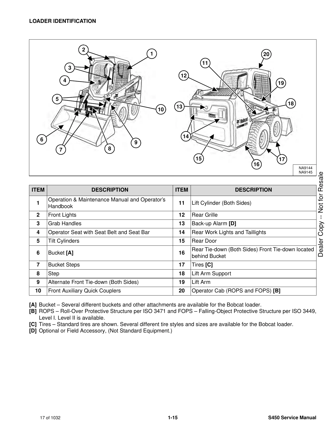
LOADER IDENTIFICATIONp. 17
+SAFETY AND MAINTENANCEp. 19
+LIFTING AND BLOCKING THE LOADERp. 23
+LIFT ARM SUPPORTp. 25
Descriptionp. 25
Installingp. 26
Removingp. 27
+OPERATOR CABp. 29
Descriptionp. 29
Cab Door Sensorp. 29
Raisingp. 30
Loweringp. 31
+TRANSPORTING THE LOADER ON A TRAILERp. 33
Loading And Unloadingp. 33
Fasteningp. 33
+TOWING THE LOADERp. 35
+REMOTE START TOOL KIT – MEL1563p. 37
Remote Start Tool – MEL1563p. 37
Service Tool Harness Communicator – MEL1566p. 39
Remote Start Procedurep. 39
+REMOTE START TOOL (SERVICE TOOL) KIT – 7217666p. 43
Descriptionp. 43
Remote Start Tool (Service Tool) – 7022042p. 44
Loader Service Tool Harness – 6689747p. 45
Computer Service Tool Harness – 6689746p. 46
Remote Start Procedurep. 47
+SERVICE SCHEDULEp. 51
Maintenance Intervalsp. 51
+ENGINE AIR CLEANERp. 53
+ENGINE COOLING SYSTEMp. 55
Maintenance Platformp. 55
Cleaningp. 55
Checking And Adding Coolantp. 58
Removing And Replacing Coolantp. 59
+FUEL SYSTEMp. 61
Fuel Specificationsp. 61
Biodiesel Blend Fuelp. 61
Filling The Fuel Tankp. 62
Fuel Filtersp. 63
Removing Air From The Fuel Systemp. 65
+ENGINE LUBRICATION SYSTEMp. 67
Checking And Adding Engine Oilp. 67
Engine Oil Chartp. 67
Removing And Replacing Oil And Filterp. 68
+HYDRAULIC / HYDROSTATIC SYSTEMp. 71
Checking And Adding Fluidp. 71
Hydraulic / Hydrostatic Fluid Chartp. 71
Removing And Replacing Hydraulic Fluidp. 72
Removing And Replacing Hydraulic / Hydrostatic Filterp. 75
Removing And Replacing Hydraulic Charge Filterp. 76
Replacing Reservoir Breather Capp. 78
+FINAL DRIVE TRANSMISSION (CHAINCASE)p. 79
Checking And Adding Fluidp. 79
Removing And Replacing Fluidp. 79
+BOB-TACH (HAND LEVER)p. 81
Inspection And Maintenancep. 81
+BOB-TACH (POWER)p. 83
Inspection And Maintenancep. 83
+LUBRICATING THE LOADERp. 85
Lubrication Locationsp. 85
+TIRE MAINTENANCEp. 89
Wheel Nutsp. 89
Rotatingp. 89
Mountingp. 90
+SPARK ARRESTER MUFFLERp. 91
+PIVOT PINSp. 93
Inspection And Maintenancep. 93
+LOADER STORAGE AND RETURN TO SERVICEp. 95
Storagep. 95
Return To Servicep. 95
+STOPPING THE ENGINE AND LEAVING THE LOADERp. 97
+EMERGENCY EXITp. 99
Rear Window Identificationp. 99
Rear Window Removal (Latches)p. 99
Rear Window Removal (Rubber Cord)p. 99
External Access (Rear Window With Latches)p. 100
External Access (Rear Window With Rubber Cord)p. 100
Front Doorp. 101
+SEAT BELTp. 103
Inspection And Maintenancep. 103
+HYDRAULIC SYSTEMp. 105
HYDRAULIC / HYDROSTATIC SCHEMATICSp. 109
+HYDRAULIC SYSTEM INFORMATIONp. 125
Glossary Of Hydraulic / Hydrostatic Symbolsp. 125
Troubleshootingp. 129
+CYLINDER (LIFT)p. 131
Testingp. 131
Removal And Installationp. 132
Parts Identificationp. 134
Disassemblyp. 135
Assemblyp. 137
+CYLINDER (TILT)p. 141
Testingp. 141
Removal And Installationp. 142
Base End Pivot Pin Removal And Installationp. 143
Parts Identificationp. 144
Disassemblyp. 145
Assemblyp. 147
+CYLINDER (LIFT) (AZNB11488 & ABOVE)p. 151
Parts Identificationp. 151
Disassemblyp. 152
Assemblyp. 154
+CYLINDER (TILT) (AZNB11488 & ABOVE)p. 159
Parts Identificationp. 159
Disassemblyp. 160
Assemblyp. 162
+CYLINDER (BOB-TACH)p. 167
Testingp. 167
Removal And Installationp. 168
Parts Identificationp. 169
Disassemblyp. 170
Assemblyp. 171
+MAIN RELIEF VALVEp. 175
Descriptionp. 175
Testingp. 176
Adjustingp. 178
Removal And Installationp. 179
+HYDRAULIC CONTROL VALVE (STANDARD)p. 181
Descriptionp. 181
Removal And Installationp. 182
Mount Bracket Removal And Installationp. 185
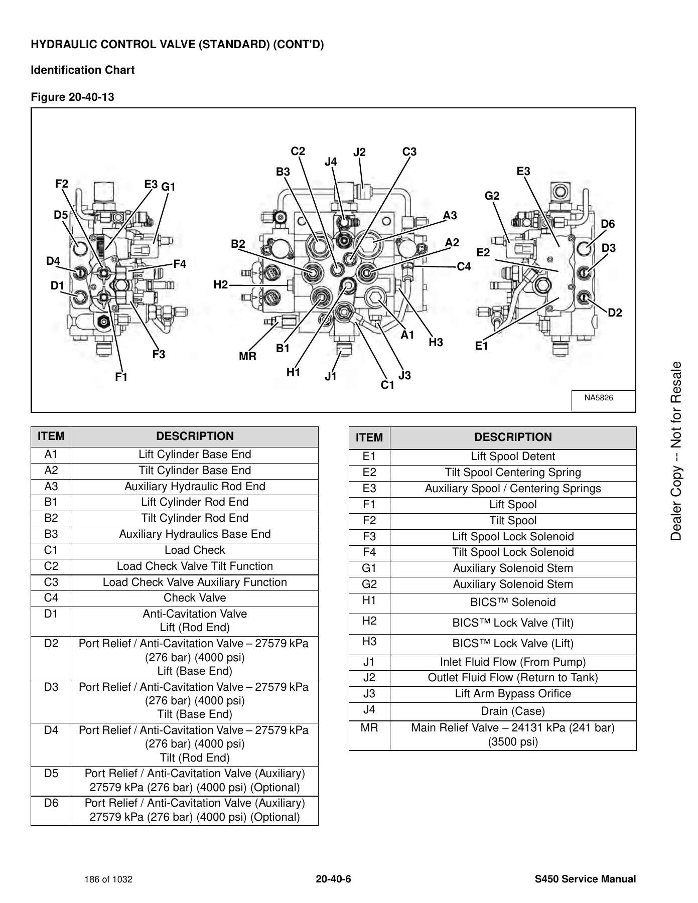
Identification Chartp. 186
Lift Load Check Valve Removal And Installationp. 187
Load Check Valve Removal And Installation (Tilt And Auxiliary)p. 188
Anti-Cavitation Valve Removal And Installation (Lift, Rod End)p. 189
Port Relief / Anti-Cavitation Valve Removal And Installation (Lift, Base End)p. 189
Port Relief / Anti-Cavitation Valve Removal And Installation (Tilt, Base End)p. 190
Port Relief / Anti-Cavitation Valve Removal And Installation (Tilt, Rod End)p. 190
Port Relief Valve Removal And Installationp. 191
Plug Removal And Installationp. 193
Rubber Boot Removal And Installationp. 194
End Cap Block Removal And Installationp. 194
Lift Spool And Detent Removal And Installationp. 195
Tilt Spool Removal And Installationp. 203
Auxiliary Spool Removal And Installationp. 205
Auxiliary Solenoid Removal And Installationp. 206
Solenoid Removal And Installationp. 207
Lock Valve Removal And Installationp. 208
Lift Arm Bypass Orifice Removal And Installationp. 210
Main Relief Valve Removal And Installationp. 210
Check Valve Removal And Installationp. 211
+HYDRAULIC CONTROL VALVE (ACS) OR (SJC)p. 213
Descriptionp. 213
Removal And Installationp. 213
Actuator Removal And Installation (In Loader)p. 216
Actuator Removal And Installation (Out Of Loader)p. 217
Identification Chartp. 220
Mount Bracket Removal And Installationp. 221
Lift Load Check Valve Removal And Installationp. 221
Load Check Valve Removal And Installation (Tilt And Auxiliary)p. 222
Anti-Cavitation Valve Removal And Installation (Lift, Rod End)p. 223
Port Relief / Anti-Cavitation Valve Removal And Installation (Lift, Base End)p. 223
Port Relief / Anti-Cavitation Valve Removal And Installation (Tilt, Base End)p. 224
Port Relief / Anti-Cavitation Valve Removal And Installation (Tilt, Rod End)p. 224
Port Relief Valve Removal And Installationp. 225
Plug Removal And Installationp. 227
End Cap Block Removal And Installationp. 228
Lift Spool Removal And Installationp. 228
Lift Spool Disassembly And Assemblyp. 230
Tilt Spool Removal And Installationp. 231
Tilt Spool Disassembly And Assemblyp. 232
Auxiliary Spool Removal And Installationp. 233
Auxiliary Solenoid Removal And Installationp. 234
Solenoid Removal And Installationp. 235
Lock Valve Removal And Installationp. 236
Lift Arm Bypass Orifice Removal And Installationp. 238
Main Relief Valve Removal And Installationp. 238
Check Valve Removal And Installationp. 239
+LIFT ARM BYPASS CONTROL VALVEp. 241
Descriptionp. 241
Testingp. 241
Removal And Installationp. 242
Bracket Removal And Installationp. 243
Disassembly And Assemblyp. 243
+HYDRAULIC PUMPp. 245
Descriptionp. 245
Pump Test At Quick Couplersp. 246
Direct Pump Test (Standard Section)p. 248
Direct Pump Test (Charge Section)p. 250
Removal And Installationp. 252
Hydraulic Pump Startupp. 254
Parts Identificationp. 255
Disassembly And Assemblyp. 256
+HYDRAULIC / HYDROSTATIC FILTERSp. 257
Descriptionp. 257
Housing Removal And Installationp. 257
+HYDRAULIC FLUID RESERVOIRp. 259
Descriptionp. 259
Removal And Installationp. 259
Hydraulic Fluid Screenp. 260
Gauge Removal And Installationp. 260
+OIL COOLERp. 261
Removal And Installationp. 261
+BUCKET POSITION VALVEp. 263
Descriptionp. 263
Solenoid Removal And Installationp. 263
Solenoid Testingp. 264
Removal And Installationp. 264
Disassembly And Assemblyp. 266
+BOB-TACH (POWER) BLOCK (EARLIER MODELS)p. 267
Descriptionp. 267
Removal And Installationp. 267
Disassembly And Assemblyp. 269
+BOB-TACH (POWER) BLOCK (LATER MODELS)p. 277
Descriptionp. 277
Testing Relief Valvep. 277
Removal And Installationp. 279
Disassembly And Assemblyp. 281
+FRONT AUXILIARY HYDRAULIC COUPLER BLOCKp. 287
Descriptionp. 287
Removal And Installationp. 288
Disassembly And Assembly (FFI/FI)p. 289
Disassembly And Assembly (FFH/FH)p. 291
+HYDROSTATIC SYSTEMp. 293
+HYDROSTATIC SYSTEM INFORMATIONp. 295
Descriptionp. 295
Troubleshootingp. 296
+HYDROSTATIC DRIVE MOTOR (EARLIER MODELS)p. 297
Descriptionp. 297
Removal And Installationp. 297
Parts Identificationp. 299
Disassembly And Assemblyp. 300
Shaft Seal Replacementp. 306
+HYDROSTATIC DRIVE MOTOR (LATER MODELS)p. 307
Descriptionp. 307
Removal And Installationp. 307
+CHARGE PRESSUREp. 309
Descriptionp. 309
Testingp. 309
Adjustingp. 311
Sender Removal And Installationp. 313
+HYDROSTATIC PUMPp. 315
Descriptionp. 315
Removal And Installationp. 316
Hydrostatic Pump Startupp. 317
Replenishing / High Pressure Relief Valve Removal And Installationp. 318
Parts Identification (Left Half)p. 319
Parts Identification (Right Half)p. 320
Disassemblyp. 321
Assemblyp. 328
+HYDROSTATIC PUMP (SJC)p. 335
Descriptionp. 335
Hydraulic Controller Removal And Installationp. 336
Removal And Installationp. 338
Hydrostatic Pump Startupp. 339
Parts Identificationp. 340
High Pressure Relief And Bypass Valvep. 341
Charge Relief Valvep. 342
Disassembly And Assemblyp. 343
Mechanical Neutral Adjustmentp. 356
Hydraulic Controller Neutral Adjustmentp. 358
+DRIVE BELTp. 363
Belt Adjustmentp. 363
Belt Replacementp. 363
Tensioner Pulley Removal And Installationp. 365
Tensioner Pulley Disassembly And Assemblyp. 366
+DRAIN MANIFOLDp. 367
Descriptionp. 367
Drain Manifold Removal And Installationp. 368
+DRIVE SYSTEMp. 369
+BRAKEp. 371
Descriptionp. 371
Disc Removal And Installationp. 371
+DRIVE COMPONENTSp. 373
Descriptionp. 373
Axle Seal Removal And Installationp. 374
Axle, Sprocket And Bearings Removal And Installationp. 376
Chain Removal And Installationp. 380
+CHAINCASEp. 383
Descriptionp. 383
Front Cover Removal And Installationp. 383
Center Cover Removal And Installationp. 384
+MAINFRAMEp. 385
+SEAT BARp. 389
Descriptionp. 389
Removal And Installationp. 389
Disassembly And Assemblyp. 390
Compression Spring Disassembly And Assemblyp. 391
+OPERATOR CABp. 393
Gas Spring Removal And Installationp. 393
Gas Spring Bracket Disassembly And Assemblyp. 394
Removal And Installationp. 394
+OPERATOR SEATp. 397
Removal And Installationp. 397
Seat Belt Removal And Installation (Retractable)p. 397
Seat Belt And Bracket Removal And Installation (Standard)p. 398
Seat Belt Bracket Removal And Installationp. 398
+OPERATOR SEAT (SUSPENSION)p. 399
Removal And Installationp. 399
Slide Rail Removal And Installationp. 399
Seat Belt Removal And Installationp. 400
Lower Cushion Removalp. 400
Lower Cushion Installationp. 401
Back Cushion Removal And Installationp. 401
Shock Removal And Installationp. 402
3-Point Seat Belt Removal And Installationp. 402
+BOB-TACH (HAND LEVER)p. 405
Descriptionp. 405
Removal And Installationp. 405
Lever And Wedge Disassembly And Assemblyp. 407
Pivot Pin Bushing And Seal Removal And Installationp. 409
+BOB-TACH (POWER)p. 411
Descriptionp. 411
Removal And Installationp. 411
Lever And Wedge Disassembly And Assemblyp. 413
Pivot Pin Bushing And Seal Removal And Installationp. 416
+LIFT ARMSp. 417
Removal And Installationp. 417
+REAR GRILLEp. 421
Removingp. 421
Installingp. 421
+REAR DOOR (TAILGATE)p. 423
Removal And Installationp. 423
Striker Removal And Installationp. 424
Striker Disassembly And Assemblyp. 424
Striker Adjustingp. 424
Latch Removal And Installationp. 425
+FUEL TANKp. 427
Removal And Installationp. 427
Fuel Fill Screen Removal And Installationp. 429
Fuel Level Sender Removal And Installationp. 429
+CONTROL PEDALS AND LINKAGESp. 431
Descriptionp. 431
Pedal Removal And Installationp. 431
Linkage Removal And Installationp. 432
Pedal (Adjusting)p. 433
Floor Pan Removal And Installationp. 434
+CONTROL PEDALS AND LINKAGES (ACS)p. 435
Descriptionp. 435
Pedal Removal And Installationp. 435
Linkage Removal And Installationp. 436
Pedal (Adjusting)p. 436
Floor Pan Removal And Installationp. 437
+CONTROL PEDALS AND LINKAGES (SJC)p. 439
+CONTROL PANELp. 441
Descriptionp. 441
Removal And Installationp. 442
Disassembly And Assemblyp. 443
Linkage Removal And Installationp. 445
Pintle Arm Disassembly And Assemblyp. 449
Linkage Neutral (Adjusting)p. 450
Linkage Travel (Adjusting)p. 454
Shock Removal And Installationp. 458
+CONTROL PANEL (SJC)p. 459
Descriptionp. 459
Removal And Installationp. 459
+CONTROL HANDLE / LEVERp. 461
Descriptionp. 461
Lever Removal And Installationp. 461
Boot Removal And Installationp. 462
+CONTROL HANDLE / LEVER (ACS)p. 463
Descriptionp. 463
Handle Sensor Removal And Installationp. 463
Handle Removal And Installationp. 466
Handle Disassembly And Assemblyp. 467
Lever Removal And Installationp. 467
Boot Removal And Installationp. 468
+CONTROL HANDLE / LEVER (SJC)p. 469
Descriptionp. 469
Joystick Testingp. 469
Joystick Removal And Installationp. 470
+WINDOW (REAR)p. 471
Rear Window Identificationp. 471
Removal (Rubber Cord)p. 471
Installation (Rubber Cord)p. 472
Removal And Installation (Latches)p. 474
Disassembly And Assembly (Latches)p. 474
+WINDOW (TOP)p. 475
Removal And Installationp. 475
+WINDOW (SIDE)p. 477
Removal And Installationp. 477
+CAB DOORp. 479
Descriptionp. 479
Removal And Installationp. 479
Disassembly And Assemblyp. 480
Aligningp. 481
Adjustingp. 482
Checking Operationp. 482
+ARMRESTp. 483
Descriptionp. 483
Removal And Installationp. 483
Disassembly And Assemblyp. 484
+LEFT SIDE LOWER PANELp. 487
Removal And Installationp. 487
Disassembly And Assemblyp. 490
+RIGHT SIDE LOWER PANELp. 491
Removal And Installationp. 491
Disassembly And Assemblyp. 493
+HEADLINERp. 495
Removal And Installationp. 495
+ELECTRICAL SYSTEM AND ANALYSISp. 497
ELECTRICAL SCHEMATICSp. 503
+ELECTRICAL SYSTEM INFORMATIONp. 663
Glossary Of Electrical Symbolsp. 663
Standard Cab Harness Connectorsp. 666
Deluxe Cab Harness Connectorsp. 667
Mainframe / Engine Harness Connectors – Manual Controls (Earlier Models)p. 668
Mainframe / Engine Harness Connectors – SJC/ACS Controls (Earlier Models)p. 669
Mainframe / Engine Harness Connectors – Manual Controls (Later Models)p. 670
Mainframe / Engine Harness Connectors – SJC/ACS Controls (Later Models)p. 671
Descriptionp. 672
Fuse And Relay Location / Identificationp. 672
Troubleshootingp. 676
Solenoid Testingp. 677
+BATTERYp. 679
Servicingp. 679
Maintaining Battery Charge Levelp. 679
Battery Service During Machine Storagep. 679
Battery Testingp. 680
Battery Chargingp. 680
Using A Booster Battery (Jump Starting)p. 681
Removal And Installationp. 682
+ALTERNATORp. 687
Belt Adjustmentp. 687
Belt Replacementp. 687
Charging System Inspectionp. 688
Alternator Voltage Testingp. 689
Low Voltage Testingp. 689
High Voltage Testingp. 690
Removal And Installationp. 691
Parts Identificationp. 692
+STARTERp. 693
Testingp. 693
Removal And Installationp. 693
Parts Identificationp. 694
+INSTRUMENT PANELSp. 695
Left Panelp. 695
Display Screenp. 697
Right Panel (Standard Key Panel)p. 698
Right Panel (Keyless Start Panel)p. 699
Right Panel (Deluxe Instrumentation Panel)p. 700
Left Switch Panelp. 702
Right Switch Panelp. 702
Left Side Lower Panelp. 703
Right Side Lower Panelp. 703
Left Panel Removal And Installationp. 704
Right Panel (Standard Key Panel) Removal And Installationp. 704
Right Panel (Keyless Start Panel) Removal And Installationp. 705
Right Panel (Deluxe Instrumentation Panel) Removal And Installationp. 705
Key Switch Disassembly And Assemblyp. 706
Alarm Disassembly And Assemblyp. 706
Left Switch Panel Removal And Installationp. 707
Right Switch Panel Removal And Installationp. 707
+LIGHTSp. 709
Front Removal And Installationp. 709
Rear Removal And Installationp. 710
Cab Light Removal And Installationp. 710
+BOBCAT CONTROLLERS (ACS AND AUXILIARY)p. 711
Descriptionp. 711
Connector And Wire Identificationp. 712
Removal And Installationp. 716
+BOBCAT CONTROLLER (GATEWAY)p. 717
Descriptionp. 717
Connector Identificationp. 718
Removal And Installationp. 721
+BOBCAT CONTROLLER (SJC) (DRIVE)p. 723
Descriptionp. 723
Connector Identificationp. 724
Removal And Installationp. 726
+DIAGNOSTIC SERVICE CODESp. 727
Viewing Service Codesp. 727
Service Codes Listp. 728
+BOBCAT INTERLOCK CONTROL SYSTEM (BICS™)p. 735
Descriptionp. 735
Inspecting The BICS™ (Engine STOPPED – Key ON)p. 736
Inspecting Deactivation Of The Auxiliary Hydraulics System (Engine STOPPED – Key ON)p. 736
Inspecting The Seat Bar Sensor (Engine RUNNING)p. 736
Inspecting The Traction Lock And Parking Brake (Engine RUNNING)p. 736
Inspecting The Lift Arm Bypass Controlp. 736
Inspecting Deactivation Of Lift And Tilt Functions (ACS And SJC)p. 736
Troubleshootingp. 737
+SEAT BAR SENSORp. 739
Descriptionp. 739
Troubleshootingp. 739
Testingp. 740
Removalp. 741
Installationp. 742
Bobcat Interlock Control System (BICS™) Circuit Testp. 744
+TRACTION LOCKp. 747
Descriptionp. 747
Troubleshootingp. 748
Inspectingp. 749
+CONTROL SYSTEM (ACS)p. 751
Descriptionp. 751
Troubleshootingp. 752
Handle Sensor Connector Disassembly And Assemblyp. 753
Switch Handle Removalp. 754
Switch Handle Installationp. 756
Actuator Connector Disassembly And Assemblyp. 759
Handle Lock Solenoid Removal And Installationp. 760
Handle Lock Solenoid Disassembly And Assemblyp. 760
Foot Sensor Removal And Installationp. 761
Foot Sensor Disassembly And Assemblyp. 762
Foot Sensor Lock Solenoid Removal And Installationp. 762
+ELECTRICAL / HYDRAULIC CONTROLSp. 763
Identification Chartp. 763
Descriptionp. 764
Identification Chart ACD Group 0p. 765
Identification Chart ACD Group 1p. 766
Identification Chart ACD Group 2p. 767
Identification Chart ACD Group 3p. 768
+ELECTRICAL / HYDRAULIC CONTROLS (ACS)p. 769
Identification Chartp. 769
Descriptionp. 770
Identification Chart ACD Group 0p. 771
Identification Chart ACD Group 1p. 772
Identification Chart ACD Group 2p. 773
Identification Chart ACD Group 3p. 774
+ELECTRICAL / HYDRAULIC CONTROLS (SJC)p. 775
Identification Chartp. 775
Descriptionp. 776
Identification Chart ACD Group 0p. 777
Identification Chart ACD Group 1p. 778
Identification Chart ACD Group 2p. 779
Identification Chart ACD Group 3p. 780
+SERVICE PC (LAPTOP COMPUTER)p. 781
Connecting Remote Start Toolp. 781
Connecting Remote Start Tool (Service Tool)p. 781
+CALIBRATIONp. 783
Descriptionp. 783
Actuator Testingp. 783
Lift And Tilt Calibration (SJC)p. 786
Hydrostatic Pump Calibration (SJC)p. 788
Lift And Tilt Calibration (ACS)p. 793
+STEERING DRIFT COMPENSATION (OPERATOR MODE)p. 795
Descriptionp. 795
Operationp. 796
+STEERING DRIFT COMPENSATION (SERVICE MODE)p. 797
Descriptionp. 797
Operationp. 797
+FLYWHEEL RPM SENSORp. 799
Descriptionp. 799
Removalp. 799
Installationp. 800
+CONTROL PANEL SETUPp. 801
Right Panel Setup (Deluxe Instrumentation Panel)p. 801
+PASSWORD SETUP (DELUXE INSTRUMENTATION PANEL)p. 805
Password Descriptionp. 805
Changing The Owner Passwordp. 805
Changing The User Passwordsp. 806
Password Lockout Featurep. 806
+PASSWORD SETUP (KEYLESS START PANEL)p. 807
Password Descriptionp. 807
Changing The Owner Passwordp. 807
Password Lockout Featurep. 807
+MAINTENANCE CLOCKp. 809
Descriptionp. 809
Setupp. 810
Resetp. 813
+BACK-UP ALARM SYSTEMp. 815
Descriptionp. 815
Inspectingp. 815
Adjusting Switch Positionp. 816
Troubleshooting (Standard And ACS)p. 817
Troubleshooting (Joystick)p. 818
Alarm Removal And Installationp. 819
Switch Removal And Installationp. 819
+FRONT HORNp. 821
Removal And Installationp. 821
Troubleshootingp. 822
Troubleshooting (Joystick)p. 823
+ENGINE SERVICEp. 825
+ENGINE INFORMATIONp. 829
Descriptionp. 829
Specificationsp. 830
Torque Valuesp. 833
Troubleshootingp. 833
Engine Removal And Installationp. 835
Engine Mount Replacementp. 843
Compression – Testingp. 844
+ENGINE SPEED CONTROL (HAND)p. 847
Removal And Installationp. 847
Disassembly And Assemblyp. 847
Cable Removal And Installationp. 848
+ENGINE SPEED CONTROL (FOOT) (SJC)p. 849
Descriptionp. 849
Removal And Installationp. 849
Disassembly And Assemblyp. 851
Pedal (Adjusting)p. 852
Floor Pan Removal And Installationp. 852
+MUFFLERp. 853
Removal And Installationp. 853
+AIR CLEANERp. 855
Housing Removal And Installationp. 855
+ENGINE COOLING SYSTEMp. 857
Radiator / Oil Cooler Removal And Installationp. 857
Hydraulic Fan Descriptionp. 860
Fan Duct Removal And Installationp. 860
Hydraulic Fan Motor Assembly Removal And Installation (Earlier Models)p. 861
Hydraulic Fan Motor Removal And Installation (Earlier Models)p. 862
Hydraulic Fan Motor Disassembly And Assembly (Earlier Models)p. 863
Hydraulic Fan Motor Assembly Removal And Installation (Later Models)p. 865
Fan Removal And Installation (Later Models)p. 866
Hydraulic Fan Motor Removal And Installation (Later Models)p. 867
Hydraulic Fan Motor Disassembly And Assembly (Later Models)p. 868
Fan Shroud Removal And Installationp. 874
Water Pump Removal And Installationp. 874
Water Pump Disassembly And Assemblyp. 875
Thermostat Housing Removal And Installationp. 876
Thermostat – Testingp. 877
+LUBRICATION SYSTEMp. 879
Oil Pan Removal And Installationp. 879
Relief Valve – Inspectionp. 879
Oil Pump Removal And Installationp. 880
Oil Pump Inspectionp. 880
Engine Oil Pressure – Testingp. 881
+FUEL SYSTEMp. 883
Fuel Shutoff Solenoid – Testingp. 883
Fuel Shutoff Solenoid Removal And Installationp. 883
Fuel Injection Pump – Testingp. 884
Fuel Injection Pump Removal And Installationp. 885
Governor Disassembly And Assemblyp. 889
Fuel Camshaft Removal And Installationp. 890
Fuel Injection Pump – Timingp. 890
Fuel Injector Removal And Installationp. 892
Fuel Injector Nozzle Pressure – Checkingp. 893
Nozzle Spray Conditionp. 894
Valve Seat Tightnessp. 894
+CYLINDER HEADp. 895
Glow Plugs – Testingp. 895
Glow Plugs Removal And Installationp. 895
Valve Clearance Adjustmentp. 896
Valve Timing – Inspectingp. 897
Cylinder Head Removal And Installationp. 898
Cylinder Head Disassembly And Assemblyp. 901
Cylinder Head – Servicingp. 901
Cylinder Head Top Clearancep. 902
Valve Guide – Inspectingp. 902
Valve Guide Removal And Installationp. 903
Reconditioning The Valve And Valve Seatp. 903
Valve Springp. 905
Valve Tappetsp. 906
Rocker Arm And Shaft – Inspectingp. 906
Push Rod Alignment – Inspectingp. 907
+CRANKSHAFT AND PISTONSp. 909
Piston And Connecting Rod Removal And Installationp. 909
Piston And Connecting Rod – Servicingp. 910
Cylinder Bore – Inspectingp. 913
Connecting Rod Alignmentp. 913
Crankshaft Gear Removal And Installationp. 914
Crankshaft And Bearings Removal And Installationp. 914
Crankshaft And Bearings – Servicingp. 916
+CAMSHAFT AND TIMING GEARSp. 921
Timing Gearcase Cover Removal And Installationp. 921
Timing Gears Backlash – Inspectionp. 923
Idler Gear And Camshaft Removal And Installationp. 924
Camshaft – Servicingp. 925
Idler Gear And Shaft – Servicingp. 926
+FLYWHEEL AND HOUSINGp. 927
Flywheel Removal And Installationp. 927
Ring Gear Removal And Installationp. 927
Housing Removal And Installationp. 928
+HEATING, VENTILATION AND AIR CONDITIONING (HVAC)p. 931
+AIR CONDITIONING SYSTEM FLOWp. 933
Descriptionp. 933
Chartp. 934
Componentsp. 935
Safety Equipmentp. 938
+REGULAR MAINTENANCEp. 939
Filtersp. 939
Belt Adjustmentp. 940
Belt Replacementp. 940
Air Conditioning Condenserp. 941
Air Conditioning Lubricationp. 941
Air Conditioning Service Chartp. 942
Evaporator / Heater Coilp. 943
+TROUBLESHOOTINGp. 945
Blower Motor Does Not Operatep. 945
Blower Motor Operates Normally, But Air Flow Is Insufficientp. 945
Insufficient Cooling Although Air Flow And Compressor Operation Are Normalp. 945
The Compressor Does Not Operate At All, Or Operates Improperlyp. 945
Gauge Pressure Related Troubleshootingp. 946
Troubleshooting Treep. 948
Temperature / Pressure Chartp. 952
Poor A/C Performancep. 954
HVAC Repair And Leaksp. 955
Electrical Systemp. 955
Engine Coolant Bypassing The Heater Valvep. 962
Heater Valve Not Opening Or Closingp. 963
+SYSTEM CHARGING AND RECLAMATIONp. 965
Refrigerant Identificationp. 965
Reclamation And Charging With Recovery / Charging Unitp. 966
+COMPRESSORp. 969
Removal And Installationp. 969
Oilp. 970
Oil Checkp. 971
+CONDENSERp. 973
Removal And Installationp. 973
+RECEIVER / DRIERp. 975
Receiver / Drier Removal And Installationp. 975
Pressure Switch Removal And Installationp. 976
Schrader® Valve Removal And Installationp. 977
+EVAPORATOR / HEATER UNITp. 979
Removal And Installationp. 979
+THERMOSTATp. 981
Descriptionp. 981
Removal And Installationp. 982
+EXPANSION VALVEp. 983
Removal And Installationp. 983
+EVAPORATOR COILp. 985
Removal And Installationp. 985
+HEATER COILp. 987
Removal And Installationp. 987
+BLOWER FANp. 989
Removal And Installationp. 989
Disassembly And Assemblyp. 989
+HEATER VALVEp. 993
Removal And Installationp. 993
+SPECIFICATIONSp. 995
+(S450) LOADER SPECIFICATIONSp. 997
Machine Dimensionsp. 997
Performancep. 998
Enginep. 998
Drive Systemp. 999
Controlsp. 999
Hydraulic Systemp. 1000
Electrical Systemp. 1001
Capacitiesp. 1001
Tiresp. 1002
+TECHNICAL SERVICE GUIDE SPECIFICATIONSp. 1003
Enginep. 1003
Engine Torquesp. 1003
Cooling Systemp. 1003
Loader Torquesp. 1004
Hydraulic / Hydrostatic Systemp. 1004
Fuel Consumptionp. 1004
+TORQUE SPECIFICATIONS FOR BOLTSp. 1005
Torque For General SAE Boltsp. 1005
Torque For General Metric Boltsp. 1006
+HYDRAULIC CONNECTION SPECIFICATIONSp. 1007
Straight Thread O-ring Fittingp. 1007
Flare Fittingp. 1008
Tubelines And Hosesp. 1008
+HYDRAULIC / HYDROSTATIC FLUID SPECIFICATIONSp. 1009
+CONVERSIONSp. 1011
Decimal And Millimeter Equivalent Chartp. 1011
U.S. To Metric Conversion Chartp. 1011
+SERVICE TOOLS REQUIREDp. 1013
Remote Start Toolsp. 1013
Hydraulic Toolsp. 1014
Mainframe And Drive Toolsp. 1017
Electrical Toolsp. 1020
Engine Toolsp. 1021
HVAC Toolsp. 1026
ALPHABETICAL INDEXp. 1027
Altogether, this S450 skid-steer service manual gives a technician the complete picture of how the machine is built, how it should be tested, and how each system is disassembled, repaired and reassembled to factory specification. The hydraulic and hydrostatic sections alone contain full schematics and symbol glossaries; the electrical section carries controller pinouts, diagnostic service codes and calibration procedures for both standard and SJC/ACS machines; and the engine section is a full Kubota V2403 workshop reference in its own right.
Engines Covered
The engine chapter and specification tables in this Bobcat S450 service manual cover the machine as delivered with the Kubota V2403-M-DI-E3 Interim Tier 4 diesel engine — 2.4 L displacement, four cylinders, naturally aspirated, liquid cooled, with glow plug cold-start assistance. Engine service details include valve clearance, injection pump timing, fuel injector nozzle pressure, cylinder head top clearance and crankshaft servicing values.
What This Bobcat S450 Service Manual Enables
- Diagnose hydraulic faults using the system schematic, symbol glossary and main relief valve testing procedure.
- Remove, disassemble and reassemble the lift and tilt cylinders using the correct gland nut torques and seal installation tools.
- Service the hydraulic control valve (standard, ACS and SJC variants) including spool, load check, anti-cavitation and port relief valve removal.
- Test and calibrate the hydrostatic pump, charge pressure and hydrostatic drive motors.
- Troubleshoot the electrical system using wiring schematics, connector assignments, fuse/relay charts and diagnostic service codes.
- Perform lift and tilt calibration (ACS and SJC) and hydrostatic pump calibration (SJC) using the documented joystick sequences.
- Rebuild the engine — cylinder head, pistons, crankshaft, camshaft, timing gears and flywheel — with factory torque values and clearances.
- Service the air conditioning system, from refrigerant charging through compressor and evaporator replacement.
- Follow the full maintenance schedule with every interval clearly specified.
Why Correct Service Information Matters on an S450
Skid-steer loaders run hydraulic pressures above 3,000 psi and hydrostatic drive circuits that are sensitive to contamination and calibration. An S450 is also a compact machine with tight access to the control valve, the hydrostatic pump and the rear of the engine — knowing the correct sequence before you start saves hours of rework and reduces the risk of damaged seals, bent tubelines or mis-timed components. This Bobcat S450 repair manual gives you the torque values, clearances, tools and step-by-step procedures that the machine was designed around, so the repair is done right the first time.
Instant PDF Delivery
The Bobcat S450 Skid-Steer Loader Service Manual 6990812 is delivered as a downloadable PDF as soon as payment is complete — no shipping, no waiting for a physical book. The file can be opened on any laptop, desktop, tablet or smartphone, and pages can be printed for use in the workshop so you can keep the clean copy safe. Whether you are a professional technician, a fleet maintenance manager or an owner-operator maintaining your own S450, this service manual gives you the full factory-level procedure set in one searchable document.
Reviews
There are no reviews yet.