Description
BOMAG BW27 RH-4i Rubber Tire Roller Service Manual – Document 00892289
This is the full BOMAG service manual for the BW27 RH-4i rubber tire roller, published under document number 00892289. It is the workshop reference for repairing, adjusting and diagnosing this pneumatic tired roller, spanning mechanical overhaul of the front axle and travel gear through to EMR4 engine management fault code readouts and hydraulic circuit troubleshooting. Every section is written for the technician working on the machine, with tightening torques, component descriptions and system-level diagnostics throughout.
File Details
- Manual type: Service Manual
- Brand: BOMAG (Fayat Group)
- Model: BW27 RH-4i Rubber Tire Roller
- Document number: 00892289
- Language: English
- Page count: 706
- File format: PDF
- Serial numbers covered: S/N 101 538 12 … / S/N 861 538 23 … / S/N 861 538 24 … / S/N 861 538 25 …
Complete PDF Bookmark Tree
Complete Bookmarks
The complete bookmarks in the “BOMAG BW27 RH-4i Rubber Tire Roller Service Manual 00892289 – PDF Download” are as follows:
+BW 27 RH-4ip. 1
S/N 101 538 12 …. S/N 861 538 23 ….p. 1
+Rubber tire rollerp. 1
1.1 Introductionp. 8
+Safety regulationsp. 9
Important notesp. 9
Generalp. 9
Transport work with cranes and lifting tacklep. 9
Precautions and codes of conduct for welding workp. 9
Operation of high-voltage systemsp. 10
Old oilsp. 10
Hydraulicsp. 11
Fuelsp. 11
Hot fuelsp. 11
Synthetic rubberp. 11
Poisonous substancesp. 11
Enginep. 12
Air conditioning systemp. 12
Batteryp. 13
Special safety regulationsp. 13
+General repair instructionsp. 14
Generalp. 14
Electricsp. 14
Batteryp. 15
Generatorp. 16
Starter motorp. 16
Hydraulic systemp. 17
Air conditioning systemp. 18
+Notes on cleanliness for Common Rail enginesp. 19
+Fuel hosesp. 21
+Gaskets and mating surfacesp. 22
+Feather keys and keywaysp. 23
+Ball and roller bearingsp. 23
+Screws and nutsp. 24
Fig. 8 Identification of screwsp. 25
Fig. 9 Identification of nutsp. 25
Fig. 10 Identification of nuts in clock systemp. 26
Fig. 11p. 26
Fig. 12p. 27
+Tightening torquesp. 28
2 Pneumatic tires rollersp. 33
+Rubber tire rollerp. 34
+Flexible and economical compactionp. 34
Fig. 13p. 35
Fig. 14 Tire pressurep. 35
+Fig. 15p. 36
+Technical datap. 38
Fig. 16p. 38
Tablesp. 40
Noise valuep. 42
+Vibration valuep. 42
+4.1 General notes on maintenancep. 44
Notes on the fuel systemp. 44
Notes on the performance of the enginep. 44
Notes on the cooling systemp. 44
Notes on the hydraulic systemp. 44
+4.2 Fuels and lubricantsp. 45
+Engine oilp. 45
Fuelsp. 46
Coolantp. 46
Mineral oil based hydraulic oilp. 47
Bio-degradable hydraulic oilp. 47
Gear oilp. 47
Lubrication greasep. 47
4.3 Table of fuels and lubricantsp. 48
4.4 Running-in instructionsp. 49
+4.5 Maintenance tablep. 50
+Overviewp. 54
+5.2 Service the battery, check the main battery switchp. 57
Fig. 3p. 58
+Checking the main battery switchp. 58
+5.3 Main battery switchp. 58
+Fig. 5p. 58
No. 1 = Main battery switchp. 58
+5.4 Starting with jump wiresp. 59
+5.5 Level sensor in diesel tank (R03)p. 59
+5.6 Differential pressure switches hydraulic oil filter, B21and B22p. 60
Fig. 1p. 60
Fig. 2 Monitoring board, A15p. 60
+5.7 Brake oil temperature switch, B148p. 60
Fig. 1p. 60
Fig. 2 Monitoring board, A15p. 60
+5.8 Brake pressure switches, B12 and B102p. 61
Fig. 1p. 61
Fig. 2 Monitoring board, A15p. 61
+5.9 Float switch in water tank, B33p. 62
Fig. 1 Float switch (normally closed)p. 62
Fig. 2 Monitoring board, A15p. 62
+5.10 Air filter vacuum switchp. 63
+Vacuum switch, B03p. 63
Fig. 3p. 63
Fig. 4 Monitoring board, A15p. 63
+5.11 Description of indicators and control elementsp. 64
Fig. 5p. 64
+Fig. 6p. 65
No. 2 = Instrument clusterp. 65
Fig. 7p. 66
Fig. 8p. 66
+5.12 Fuse assignmentp. 67
+Central electricsp. 67
+Main fusesp. 69
+Fuse, cabinp. 70
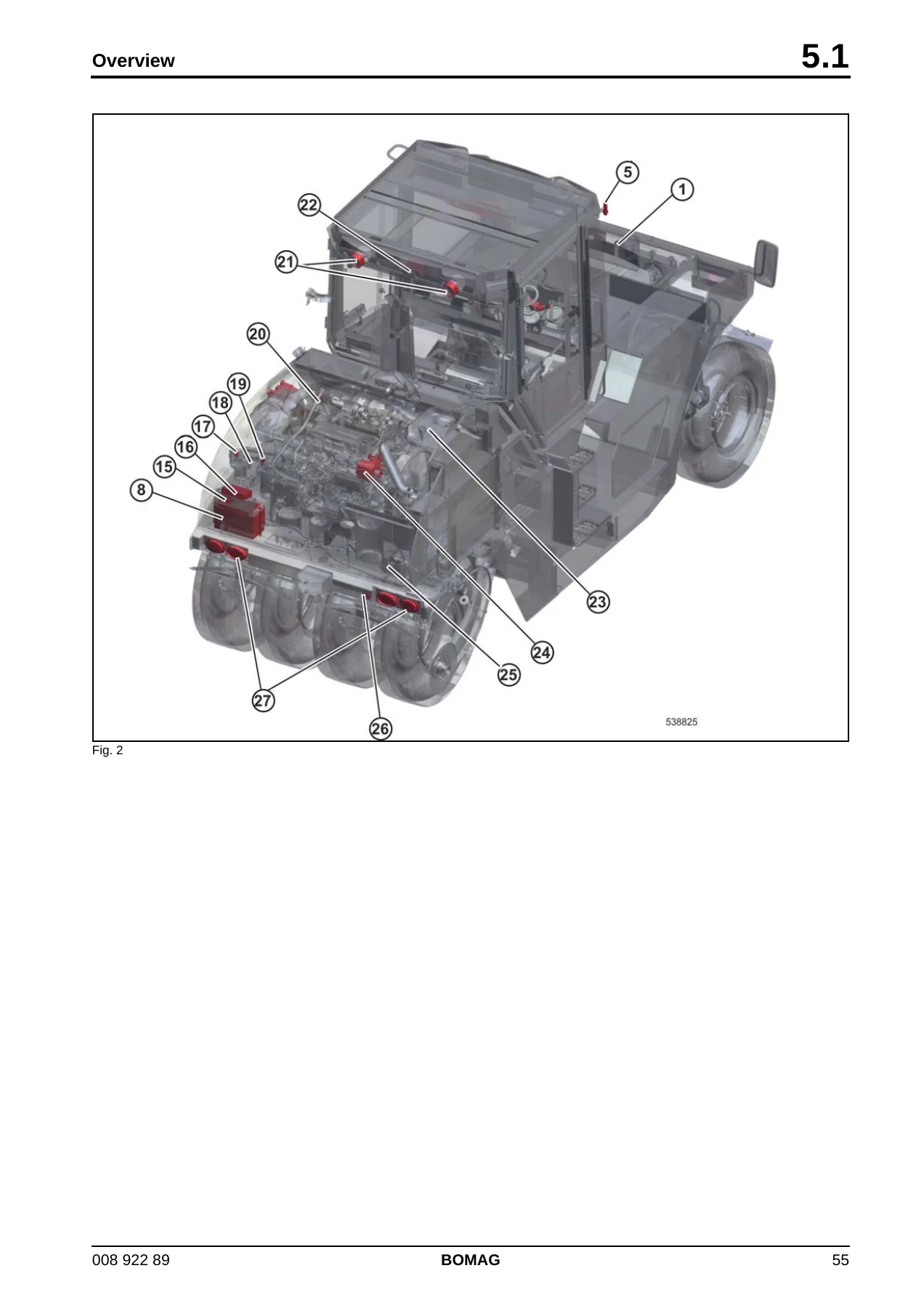
+Overview of electric componentsp. 71
6 Electronic modulesp. 87
6.1 Module description A04p. 89
+6.2 Electric module A108p. 99
7 Module description A100p. 103
+7.1 Steering column locking module, A100p. 104
+Description UPM03p. 104
Description of hardwarep. 104
+Description of functionp. 105
8 Speedometer Modulep. 107
+8.1 Speedometer modulep. 108
+Fig. 1 Speedometer modulep. 108
Fig. 2p. 112
+9.1 EMR4 system overviewp. 113
Fig. 3p. 114
Fig. 4p. 114
Fig. 5 System overviewp. 115
Fig. 6 Diagnostic linkp. 115
Fig. 7p. 116
Fig. 8p. 116
+9.2 EMR4 system componentsp. 117
+EMR-3 system in connection with injection system and electricsp. 117
Fig. 9 Injection systemp. 117
Fig. 10 Electronic engine controlp. 118
+9.3 Exhaust gas after-treatmentp. 119
Generalp. 119
+Exhaust gas recirculation (EGR)p. 119
+DPF-systemp. 120
Fig. 12p. 120
Fig. 13p. 120
Fig. 14 DPF modulep. 121
+9.4 Fuel control unit (FCU)p. 122
+Fuel Control Unit Y137p. 122
+9.5 Injectorp. 123
+Injectors, Y147, Y148, Y149, Y166, (Y169 and Y170)p. 123
Fig. 16p. 123
Fig. 17p. 123
+9.6 Crankshaft speed sensorp. 124
+Speed sensorp. 124
Fig. 18 Crankshaft speed sensorp. 124
Fig. 19p. 124
+9.7 Camshaft speed sensorp. 124
+Speed sensorp. 124
Fig. 20p. 124
Fig. 21p. 124
Fig. 22p. 125
Fig. 23p. 125
+9.8 Rail pressure sensorp. 125
+Pressure sensorp. 125
+Removing the pressure sensorp. 125
Fig. 25p. 126
Fig. 26p. 126
+Installing the pressure sensorp. 126
+9.9 EMR coolant temperature sensorp. 127
+Temperature sensorp. 127
Fig. 28 Coolant temperature sensorp. 127
Fig. 29p. 127
+9.10 Fuel pressure sensorp. 127
+9.11 Charge air temperature – charge air pressure sensorp. 128
+9.12 Oil pressure sensorp. 128
+Pressure sensor, B88p. 128
Fig. 32 Oil pressure sensorp. 128
Fig. 33p. 128
Fig. 34p. 129
Fig. 35p. 129
+9.13 Sensor, water in fuelp. 130
+Sensor, B124p. 130
Fig. 36p. 130
Fig. 37p. 130
+9.14 Fuel pre-heatingp. 131
+Fuel pre-heating (option)p. 131
+9.15 Heating flange on enginep. 131
+Heating flange R19p. 131
Fig. 1 Heating flangep. 131
Fig. 2p. 131
Fig. 3p. 132
+9.16 Charge control light, operating hour meterp. 132
Fig. 1 Generatorp. 132
+Charge control lampp. 132
Fig. 1 Monitoring board, A15p. 132
Operating hour meter, P00p. 133
+9.17 System faults per flashing codep. 133
+Engine protection function of the electric engine controllerp. 133
+Deleting the error logp. 135
10 List of EMR4 fault codesp. 137
+10.1 List of EMR4 fault codesp. 139
+11.1 Overviewp. 244
+11.2 Diesel enginep. 246
Fig. 1 Deutz diesel engine TCD 4.1 L4p. 246
+11.3 Engine description TCD 4.1p. 247
+View from the rightp. 247
Fig. 2 Deutz diesel engine TCD 4.1 L4p. 247
+View from the leftp. 248
Fig. 3 Deutz diesel engine TCD 4.1 L4p. 248
+Descriptionp. 248
Fig. 4 Exhaust gas turbocharger with Wastegatep. 250
+11.4 Lubrication oil circuit TCD 4.1 / 6.1p. 251
+Overviewp. 251
Fig. 5 Lubrication oil schematicp. 251
+11.5 Coolant circuit TCD 4.1 / 6.1p. 252
+Overviewp. 252
Fig. 6 Coolant circuitp. 252
+11.6 Common Rail System (CRS) TCD 4.1 / 6.1p. 254
+EMR-3 system in connection with injection system and electricsp. 254
Fig. 7 Injection systemp. 254
+Componentsp. 255
Fig. 8 Fuel pumpp. 255
Fig. 9 Fuel pre-cleanerp. 256
Fig. 10 FCUp. 257
Fig. 11 High pressure pumpp. 258
Fig. 12 Railp. 259
Fig. 13 Injectorp. 260
+11.7 Exhaust gas after-treatmentp. 261
Generalp. 261
+Exhaust gas recirculation (EGR)p. 261
+DPF-systemp. 262
Fig. 15p. 262
Fig. 16p. 262
Fig. 17 DPF modulep. 263
+Fig. 18p. 264
No. 3 = Push button DPF-regenerationp. 264
+11.8 Adjust the valve clearancep. 264
+11.9 Check the engine oil levelp. 265
+11.10 Changing engine oil and oil filter cartridgep. 266
Fig. 21p. 266
Fig. 22p. 266
Fig. 23p. 266
Fig. 24p. 266
+11.11 Check the coolant levelp. 267
Fig. 25p. 267
Fig. 26p. 267
+11.12 Change the coolantp. 267
Fig. 27p. 267
Fig. 28p. 268
Fig. 29p. 268
Fig. 30p. 268
+11.13 Check the anti-freeze concentration and the condition of the coolantp. 269
+11.14 Clean the cooling fins on engine and hydraulic oil coolerp. 270
+Cleaning with compressed airp. 270
Cleaning with cold cleansing agentp. 270
+11.15 Check, clean the water separatorp. 270
Fig. 33p. 270
Fig. 34p. 271
+11.16 Replacing the fuel filter cartridgep. 271
Fig. 35p. 271
Fig. 36p. 272
+11.17 Change the fuel filter, bleed the fuel systemp. 272
+Replace the fuel filter cartridgep. 272
+Bleed the fuel systemp. 273
+11.18 Checking the ribbed V-beltp. 273
+Checking condition and tension of ribbed V-belt.p. 273
Fig. 39p. 273
Fig. 40p. 273
+11.19 Replacing ribbed V-belt and idler pulleyp. 274
+11.20 Air filter maintenancep. 274
Fig. 42p. 274
Fig. 43p. 275
Fig. 44p. 275
Fig. 45p. 275
Fig. 46p. 275
Fig. 47p. 275
+Replacing the safety elementp. 275
+11.21 Check the engine mountsp. 276
+11.22 Engine problemsp. 277
+Overviewp. 282
+12.2 Hydraulic circuitp. 284
+Open circuitp. 284
Fig. 1 Open circuitp. 284
Fig. 2 Closed circuitp. 285
+Travel pumps, A4VG105 DAp. 286
+Variable displacement pumps, A4VG105 DAp. 286
Fig. 3 A4VGp. 286
Fig. 4 Hydraulic diagram, A4VG DAp. 287
Fig. 5p. 288
Fig. 6 Valve platep. 288
Fig. 7 Bypass functionp. 289
Fig. 8 Charge pressure relief valvep. 289
Fig. 9 Pressure override valvep. 290
Fig. 10 DA-control valvep. 290
Fig. 11 Automotive travel controlp. 291
Fig. 12 Inching valvep. 292
Fig. 13 Control unitp. 292
+Swash plate principle, pumpp. 293
Fig. 14p. 293
Fig. 15p. 293
+12.4 Troubleshooting axial piston pumpsp. 295
+External gear pumpsp. 298
Fig. 16 Axial compensation of gear pumpp. 298
Fig. 17p. 298
Fig. 18p. 299
+Travel motor, A6VM 107HA2R1p. 300
+Description of functionp. 300
Fig. 19p. 300
Fig. 20p. 301
+HA2R controlp. 301
Flushing valvep. 302
+12.7 Trouble shooting, variable displacement axial piston motorp. 303
+Steering valvep. 305
+OSP steering valvep. 305
+12.9 Travel circuitp. 306
+Hydrostatic travel systemp. 306
Fig. 23 Block diagram of travel circuitp. 306
Fig. 24 Schematic of travel circuitp. 308
+Charge circuitp. 308
+Travel motorsp. 309
+Travel gearp. 310
+12.10 Steering circuitp. 312
Fig. 1p. 312
+Two steering wheelsp. 312
Fig. 1p. 313
Fig. 2 Steering axlep. 313
Fig. 3 Priority valvep. 314
+12.11 Cooling and cross-flushing of the brake housingp. 315
Fig. 1p. 315
Fig. 2 Check valve and return flow filter for cross-flushing of brake housingp. 316
+12.12 Edge cutterp. 317
Fig. 1p. 317
Control valvep. 317
+12.13 Check the hydraulic oil levelp. 319
+12.14 Replace hydraulic oil and breather filter.p. 320
+12.15 Replace hydraulic oil filterp. 321
+12.16 Replacing the bypass filterp. 322
+Overviewp. 324
+Brake systemp. 325
Fig. 1 Parking brakep. 325
Fig. 2 Service brakep. 326
+Parking brakep. 326
+Service brakep. 327
Fig. 1 Service brake, pneumatic sectionp. 328
Fig. 2 Two-way valvep. 328
Fig. 3p. 329
Fig. 4p. 329
Fig. 5 Brake housingp. 330
Fig. 6 on travel pump inching valvep. 331
Fig. 7 Pressure test port on right hand brake housingp. 331
Fig. 8 on master brake cylinderp. 331
+13.3 Stopping the machine, operating the parking brakep. 332
Fig. 9p. 332
Fig. 10p. 332
Fig. 11p. 333
+13.4 Driving the machine / braking the machinep. 333
Fig. 12p. 333
+Driving the machinep. 334
Fig. 13p. 334
Fig. 14p. 334
Fig. 15p. 334
Fig. 16p. 334
+Braking the machine (service brake)p. 334
Fig. 17p. 335
Fig. 18p. 335
Fig. 19p. 335
Fig. 20p. 335
+13.5 Multi-disc brake, function testp. 336
Fig. 21p. 336
Fig. 22p. 336
+13.6 Towing in case of an engine failurep. 337
Fig. 23p. 337
Fig. 24p. 337
+After towingp. 337
+Overviewp. 340
+Pneumatic systemp. 341
Fig. 1 Service brakep. 341
+Componentsp. 342
Fig. 2p. 342
Fig. 3p. 343
Fig. 4 3/2-way valvep. 343
Fig. 5p. 344
Fig. 6p. 344
+Air drierp. 345
+Compressorp. 346
+Overflow valvep. 346
Fig. 9p. 347
Fig. 10p. 347
+Check valvep. 348
+14.3 Operating the tire inflation systemp. 349
+Inflating the tiresp. 349
+Relieving the tire pressurep. 349
+14.4 Draining the air pressure vesselp. 350
+14.5 Change the air drier for the brake systemp. 351
+14.6 Check the supply lines for the compressorp. 351
Fig. 16p. 351
Fig. 17p. 351
+Fig. 18p. 351
15 Water sprinkling systemp. 353
+Overviewp. 354
+15.2 Operating the pressure sprinkler systemp. 355
+15.3 Service the water sprinkling systemp. 355
Fig. 3p. 355
Fig. 4p. 355
Fig. 5p. 355
Fig. 6p. 356
+15.4 Maintenance in case of frostp. 356
+Water sprinkler systemp. 356
+Ballast tankp. 357
+Fig. 9p. 357
16 Air conditioning systemp. 359
Overviewp. 360
+16.2 Physical basicsp. 362
Fig. 1p. 362
Fig. 2p. 362
+Pressure and boiling pointp. 363
Fig. 3 Steam pressure curvep. 363
Fig. 4 Pressure – Temperature Diagramp. 363
+16.3 Refrigerant R134ap. 365
Environmental aspectsp. 366
16.4 Compressor oil / refrigeration oilp. 366
+16.5 Working principle of the air conditioning systemp. 367
Fig. 1 Principle sketch of an air conditioning systemp. 367
+16.6 Monitoring devicesp. 367
Fig. 2 Monitoring chain consisting of:p. 368
+16.7 Description of componentsp. 368
+Compressorp. 368
Fig. 3 Refrigerant compressorp. 368
Fig. 4p. 369
Fig. 5p. 370
Fig. 6p. 370
Fig. 7p. 370
Fig. 8p. 371
Fig. 9p. 372
Fig. 10p. 372
Fig. 11p. 373
Fig. 12 adjustable temperature controllerp. 373
+16.8 Measuring the compressor oil levelp. 374
+16.9 Checking the magnetic clutchp. 374
Fig. 1p. 374
Fig. 2 Measuring the air gapp. 374
+Cross-section of magnetic clutchp. 375
Fig. 3 Cross-section of magnetic clutchp. 375
16.10 Inspection and maintenance workp. 375
+16.11 Servicing the V-belt for the refrigerant compressorp. 376
+Checking the V-beltp. 376
+Tightening the V-beltp. 376
Replacing the V-beltp. 376
+16.12 Service the air conditioningp. 377
+Clean the condenserp. 377
+Checking the refrigerant levelp. 377
Fig. 7p. 377
Fig. 8p. 377
Fig. 9p. 378
Fig. 10p. 378
+Checking the moisture level of the drying agentp. 378
+Checking the condition of the drier/collector unitp. 378
16.13 Drying and evacuationp. 379
16.14 Emptying in case of repairp. 380
+16.15 Leak testp. 380
Fig. 1 Electronic leak testerp. 380
Fig. 2 Soap bubble testp. 380
+Filling instructionsp. 381
Fig. 1p. 381
Filling instructionsp. 382
+16.17 Trouble shooting in refrigerant circuit, basic principlesp. 383
+Basic principlesp. 383
Fig. 2 Pressure gaugep. 384
Fig. 3 Absolute pressure gaugep. 384
Overheatingp. 384
+Supercoolingp. 385
Fig. 1 Refrigerant circuit with t, h- diagramp. 386
+16.18 Trouble shooting, refrigerant circuit diagramp. 387
Fig. 1 Refrigerant circuit diagramp. 387
+16.19 Trouble shooting procedurep. 388
+Procedurep. 388
Fig. 2 Flow diagram with measuring pointsp. 389
Fig. 3p. 392
Fig. 4p. 393
Fig. 5p. 394
Fig. 6p. 395
+Steam table for R134a
17 Replacing the cab window panesp. 403
Assembly of window panes
+Fig. 1p. 404
1 Glass panesp. 404
2 Fastening elementp. 404
3 Fixing washer and spacerp. 404
4 Washerp. 404
5 Hexagon nut, self lockingp. 404
6 Protective capp. 404
17.2 Special tools, cabin windowsp. 405
+Fig. 1p. 405
1. Locking handle for fastening elementp. 405
+Fig. 2p. 405
+Fig. 3p. 405
3. Cutterp. 405
17.3 Auxiliary materialsp. 406
+Fig. 1p. 406
4. Cutterp. 406
+Fig. 2p. 406
5. Window glass bonding agentp. 406
+Fig. 3p. 406
+Fig. 4p. 407
7. Silicone sealantp. 407
17.4 Removing and installing the window panep. 408
+Fig. 1p. 408
1. Pull large glass rests off the bonding strip (Fig. 1).p. 408
+Fig. 2p. 408
2. Clean the sealing surfaces from any adhesive material (Fig. 2).p. 408
3. Use a cutter to remove adhesive residues with glass rests.p. 408
4. Cover places without adhesive residues with an activator.p. 408
+Fig. 3p. 408
5. Insert the fastening element with washer into the bore in the glass pane (Fig. 3).p. 408
+Fig. 4p. 409
6. Turn the fixing and spacer washer hand-tight onto the thread of the fastening element (Fig. 4).p. 409
+Fig. 5p. 409
7. Lay an approx. 1 cm high triangular bead of glass pane bonding agent on the inside of the pane, approx. 1.5 cm away from the edge (Fig. 5).p. 409
+Fig. 6p. 409
8. Attach the suction lifter to the outside of the pane (Fig. 6).p. 409
9. Install the window pane so that the fastening elements fit into the bores of the fastening bars.p. 409
10. Press the glass pane against the sealing surface.p. 409
+Fig. 7p. 409
11. Assemble the washer and the self-locking hexagon nut.p. 409
12. Fasten the window pane to the fastening bar using a locking handle and a ring spanner (Fig. 7).p. 409
13. Press the protective cap onto the hexagon nut.p. 409
+Fig. 8p. 410
14. Remove the suction lifter (Fig. 8).p. 410
+Fig. 9p. 410
15. Clean the joining edges on the window pane (Fig. 9).p. 410
16. Mask the upper and lower contact areas to the cabin.p. 410
+Fig. 10p. 410
17. Apply silicone sealant evenly and under pressure first to the inside joint edge (Fig. 10).p. 410
+Fig. 11p. 410
18. Then apply silicone sealant evenly and under pressure to the outside joint edge (Fig. 11).p. 410
+Fig. 12p. 411
19. Then spray the joints from inside and outside with water containing washing up liquid (Fig. 12).p. 411
+Fig. 13p. 411
20. Treat the inside joint (Fig. 13)p. 411
+Fig. 14p. 411
21. and the outside joint (Fig. 14) with a scraper or a spattle.p. 411
18 Front axlep. 413
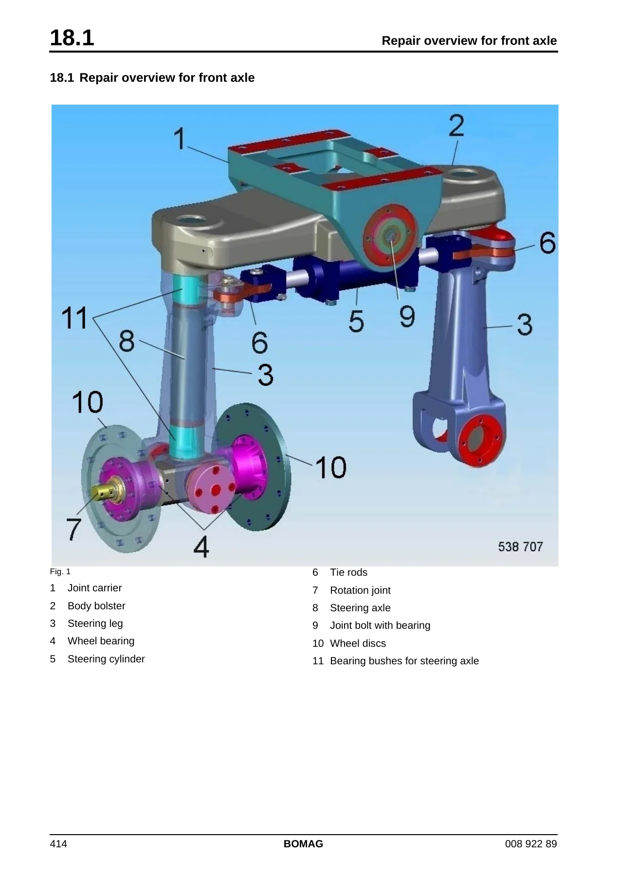
+18.1 Repair overview for front axlep. 414
+Fig. 1p. 414
1 Joint carrierp. 414
2 Body bolsterp. 414
3 Steering legp. 414
4 Wheel bearingp. 414
5 Steering cylinderp. 414
6 Tie rodsp. 414
7 Rotation jointp. 414
8 Steering axlep. 414
9 Joint bolt with bearingp. 414
10 Wheel discsp. 414
11 Bearing bushes for steering axlep. 414
+18.2 Dismantling the front axlep. 415
+Fig. 1p. 415
1. Disassemble the front axle.p. 415
2. Attach the lifting tackle to the front axle (Fig. 1).p. 415
+Fig. 2p. 415
3. Place the front axle with the top side down safely on a assembly trestle (Fig. 2).p. 415
+Fig. 3p. 415
4. Remove the locking plates from the steering arms (Fig. 3).p. 415
5. Drive bolt (1) out with a suitable drift punch and pull out the tie rods (2).p. 415
+Fig. 4p. 415
6. Remove the wheel discs (Fig. 4).p. 415
+Fig. 5p. 416
7. Remove the rear bearing cover (Fig. 5).p. 416
8. Disassemble the front bearing cover with Belleville springs, shims and backing discs.p. 416
+Fig. 6p. 416
9. Attach the lifting tackle to the wheel bearing unit.p. 416
10. Turn impact puller 1 (Fig. 6) into the thread (M24) and extract the bearing bolt with the bearing.p. 416
+Fig. 7p. 416
11. Lift the bearing unit out of the body bolster (Fig. 7).p. 416
+Fig. 8p. 416
12. Bend the lug if the locking plate open and unscrew the grooved nut 1 (Fig. 8).p. 416
+Fig. 9p. 417
13. Take off the locking plate (Fig. 9).p. 417
+Fig. 10p. 417
14. Take off the shim (Fig. 10).p. 417
15. Extract the wheel bearing using a suitable puller.p. 417
+Fig. 11p. 417
16. Disassemble the left hand holding plate (Fig. 11).p. 417
17. Disassemble the right hand holding plate .p. 417
18. Attach the lifting tackle to the body bolster.p. 417
+Fig. 12p. 417
19. Lift both steering arms out of the steering axles (Fig. 12).p. 417
20. Unscrew the steering cylinder fastening screws and disassemble the steering cylinder (1).p. 417
+Fig. 13p. 418
21. Lay the steering arms on the workbench (Fig. 13).p. 418
+Fig. 14p. 418
22. Knock out the bearing bushings 1 (Fig. 14).p. 418
+Fig. 15p. 418
23. Attach the lifting tackle to the body bolster.p. 418
24. Remove the rear bearing cover (Fig. 15).p. 418
25. Disassemble the front bearing cover with Belleville springs, shims and backing discs.p. 418
+Fig. 16p. 418
26. Press the body bolster against the joint receptacle to the stop (Fig. 16).p. 418
+Fig. 17p. 419
27. Force inner race 1 (Fig. 17) of the rocker bearing off the bolt.p. 419
28. Remove backing disc (2).p. 419
+Fig. 18p. 419
29. Unscrew the socket head cap screws (Fig. 18).p. 419
+Fig. 19p. 419
30. Turn in the forcing screws and force the joint bolt out of the body bolster (Fig. 19).p. 419
+Fig. 20p. 419
31. Take the joint bolts out of the body bolster (Fig. 20).p. 419
+Fig. 21p. 420
32. Press the body bolster against the joint receptacle to the stop (Fig. 21).p. 420
+Fig. 22p. 420
33. Force inner race 1 (Fig. 22) of the rocker bearing off the bolt.p. 420
34. Remove backing disc (2).p. 420
+Fig. 23p. 420
35. Unscrew the socket head cap screws (Fig. 23).p. 420
+Fig. 24p. 420
36. Turn in the forcing screws and force the joint bolt out of the body bolster (Fig. 24).p. 420
+Fig. 25p. 421
37. Take the joint bolts out of the body bolster (Fig. 25).p. 421
+Fig. 26p. 421
38. Take the joint receptacle out of the body bolster and lay it safely to the side (Fig. 26).p. 421
Fig. 27p. 421
+18.3 Assembling the front axlep. 422
+Fig. 1p. 422
1. Lay the body bolster with the top side down on the assembly trestle (Fig. 1).p. 422
+Fig. 2p. 422
2. Spray the receiving bores with sliding lacquer OKS 571 to ease assembly (Fig. 2).p. 422
+Fig. 3p. 422
3. Cool the steering axles down to at least -20°C with liquid oxygen.p. 422
4. Press the steering axles 1 (Fig. 3) into the body bolster until they bottom.p. 422
+Fig. 4p. 423
5. Lay the joint receptacle 1 (Fig. 4) on the assembly trestle.p. 423
6. Attach lifting tackle to steering axles with body bolster (2).p. 423
+Fig. 5p. 423
7. Assemble new seal rings (Fig. 5).p. 423
8. Oil the seal rings.p. 423
+Fig. 6p. 423
9. Oil the receiving bores for the joint bolts (Fig. 6).p. 423
+Fig. 7p. 423
10. Insert the body bolster into the joint receptacle (Fig. 7).p. 423
+Fig. 8p. 424
11. Screw in the front guide pins (M10) (Fig. 8).p. 424
12. Screw in the rear guide pins (M10) .p. 424
+Fig. 9p. 424
13. Oil and attach the front and rear joints bolts (Fig. 9).p. 424
14. Attach the assembly tool (1).p. 424
+Fig. 10p. 424
15. Pull both joint bolts in against the stop (Fig. 10).p. 424
16. Remove the assembly tool.p. 424
+Fig. 11p. 424
17. Remove the guide pins (Fig. 11).p. 424
+Fig. 12p. 425
18. Screw in the socket head cap screws from both sides (Fig. 12) and……..p. 425
+Fig. 13p. 425
19. ….. tighten (Fig. 13).p. 425
+Fig. 14p. 425
20. Assemble the front backing disc (Fig. 14).p. 425
21. Assemble the rear backing disc.p. 425
+Fig. 15p. 425
22. Spray the bearing seats and the inner bearing races with sliding lacquer OKS 571 to ease assembly (Fig. 15).p. 425
+Fig. 16p. 426
23. Attach the inner rocker bearing races with the wide outer rim forward (Fig. 16) and…..p. 426
+Fig. 17p. 426
24. …. drive in with a suitable mandrel (Fig. 17)p. 426
+Fig. 18p. 426
25. Spray the bearing seats and the outer bearing races with sliding lacquer OKS 571 to ease assembly (Fig. 18).p. 426
+Fig. 19p. 426
26. Attach the outer bearing races with the wide outer rim facing outside and drive them in with a plastic hammer (Fig. 19).p. 426
+Fig. 20p. 427
27. Assemble the rear bearing cover.p. 427
28. Tighten the hexagon screws (Fig. 20) cross-wise.p. 427
+Fig. 21p. 427
29. Insert backing disc 1 (Fig. 21) and Belleville springs (2) into the front cover.p. 427
+Fig. 22p. 427
30. Attach the front bearing cover with backing disc and Belleville springs and locate the assembly with two fastening screws (Fig. 22).p. 427
31. Push the threaded rod through joint receptacle and body bolster.p. 427
+Fig. 23p. 427
32. Tighten the threaded rod with the specified torque (Fig. 23).p. 427
+Fig. 24p. 428
33. Measure the gap (measurement „Y“) between cover and joint receptacle with a feeler gauge (Fig. 24).p. 428
34. Remove the cover again.p. 428
+Fig. 25p. 428
35. Insert shim 2 (Fig. 25) of appropriate thickness and backing disc (1) into the cover.p. 428
+Fig. 26p. 428
36. Lay the Belleville springs into the cover with the curvature pointing down (Fig. 26).p. 428
+Fig. 27p. 428
37. Assemble the cover (Fig. 27) with Belleville springs, shims and backing disc.p. 428
38. Turn in and tighten the fastening screws.p. 428
+Fig. 28p. 429
39. Turn in protection plug 1 (Fig. 28).p. 429
40. Insert the steering cylinder with fastening clamps into the grooves (2) in the body bolster.p. 429
41. Turn in and tighten the screws.p. 429
+Fig. 29p. 429
42. Lay the steering arm on the workbench (Fig. 29).p. 429
+Fig. 30p. 429
43. Attach the bottom bearing bushing (Fig. 30).p. 429
+Fig. 31p. 429
44. Attach the top bearing bushing (Fig. 31).p. 429
+Fig. 32p. 430
45. Attach the assembly tool 1 (Fig. 32).p. 430
46. Pull both bearing bushings fully in with the assembly tool.p. 430
+Fig. 33p. 430
47. Assemble new seals and apply a thin coat of oil (Fig. 33).p. 430
+Fig. 34p. 430
48. Apply some grease to the friction disc contact surface (Fig. 34).p. 430
+Fig. 35p. 430
49. Assemble the friction disc (Fig. 35).p. 430
+Fig. 36p. 431
50. Apply some grease to the friction disc seal ring (Fig. 36).p. 431
+Fig. 37p. 431
51. Assemble and grease the seal (Fig. 37).p. 431
+Fig. 38p. 431
52. Clean the steering axle (Fig. 38).p. 431
+Fig. 39p. 431
53. Spray the steering axle with sliding agent OKS 571 (Fig. 39).p. 431
+Fig. 40p. 432
54. Apply some grease to the body bolster contact surface (Fig. 40).p. 432
+Fig. 41p. 432
55. Attach the lifting tackle to the body bolster (Fig. 41).p. 432
+Fig. 42p. 432
56. Fit body bolster and steering axle together (Fig. 42).p. 432
+Fig. 43p. 432
57. Assemble the holding plate (Fig. 43).p. 432
+Fig. 44p. 433
58. Tighten the screw (Fig. 44).p. 433
+Fig. 45p. 433
59. Oil the receiving bores for the bearing bolts (Fig. 45).p. 433
+Fig. 46p. 433
60. Attach lifting tackle to the bearing shaft (Fig. 46) and……….p. 433
+Fig. 47p. 433
61. ……… stand the shaft in a hydraulic press (Fig. 47).p. 433
62. Assemble spacer (1).p. 433
63. Spray the bearing mounting surfaces with sliding agent OKS 571 .p. 433
+Fig. 48p. 434
64. Press the wheel bearing in until it bottoms (Fig. 48).p. 434
+Fig. 49p. 434
65. Turn the bearing shaft by 180° (Fig. 49).p. 434
66. Assemble spacer (1).p. 434
67. Spray the bearing mounting surfaces with sliding agent OKS 571 .p. 434
+Fig. 50p. 434
68. Press the wheel bearing in until it bottoms (Fig. 50).p. 434
+Fig. 51p. 434
69. Attach shim and locking plate (Fig. 51).p. 434
+Fig. 52p. 435
70. Attach the grooved nut with the bevelled side down and tighten it hand tight with a sickle spanner (Fig. 52).p. 435
+Fig. 53p. 435
71. If necessary loosen the grooved nut again, until a lug of the locking plate matches a groove in the grooved nut (Fig. 53).p. 435
72. Bend the lug down.p. 435
73. Perform the work steps (Fig. 51), (Fig. 52) and (Fig. 53) on both sides of the wheel bearing unit.p. 435
+Fig. 54p. 435
74. Attach the lifting tackle to the wheel bearing unit (Fig. 54).p. 435
75. Oil the receiving bores for the bearing bolts.p. 435
+Fig. 55p. 435
76. Fit wheel bearing unit and body bolster together (Fig. 55).p. 435
+Fig. 56p. 436
77. Oil and attach the front and rear joints bolts (Fig. 56).p. 436
78. Attach the assembly tool (1).p. 436
+Fig. 57p. 436
79. Pull both joint bolts in against the stop (Fig. 57).p. 436
80. Remove the assembly tool.p. 436
+Fig. 58p. 436
81. Assemble the backing discs on both sides (Fig. 58).p. 436
+Fig. 59p. 436
82. Spray the bearing seats and the inner bearing races with sliding lacquer OKS 571 to ease assembly (Fig. 59).p. 436
+Fig. 60p. 437
83. Attach the inner rocker bearing races with the wide outer rim forward (Fig. 60) and…..p. 437
84. …… drive in with a suitable mandrel.p. 437
+Fig. 61p. 437
85. Spray the bearing seats and the outer bearing races with sliding lacquer OKS 571 to ease assembly (Fig. 61).p. 437
+Fig. 62p. 437
86. Attach the outer bearing races with the wide outer rim facing outside and drive them in with a plastic hammer (Fig. 62).p. 437
+Fig. 63p. 437
87. Assemble the rear bearing cover (Fig. 63).p. 437
88. Tighten the hexagon screws cross-wise.p. 437
+Fig. 64p. 438
89. Insert backing disc 1 (Fig. 64) and Belleville springs (2) into the front cover.p. 438
+Fig. 65p. 438
90. Attach the front bearing cover with backing disc and Belleville springs and locate the assembly with two fastening screws (Fig. 65).p. 438
91. Push the threaded rod through joint receptacle and body bolster.p. 438
92. Tighten the threaded rod with the specified torque.p. 438
+Fig. 66p. 438
93. Measure the gap (measurement „Y“) between cover and joint receptacle with a feeler gauge (Fig. 66).p. 438
94. Remove the cover again.p. 438
+Fig. 67p. 439
95. Insert shim 2 (Fig. 67) of appropriate thickness and backing disc (1) into the cover.p. 439
+Fig. 68p. 439
96. Lay the Belleville springs into the cover with the curvature pointing down (Fig. 68).p. 439
+Fig. 69p. 439
97. Assemble the cover (Fig. 69) with Belleville springs, shims and backing disc.p. 439
98. Turn in and tighten the fastening screws.p. 439
99. Press in the protection plug (1).p. 439
+Fig. 70p. 439
100. Assemble the wheel discs (Fig. 70).p. 439
+Fig. 71p. 440
101. Spray the mating surfaces with sliding lacquer OKS 571 to ease assembly (Fig. 71).p. 440
102. Drive the bearing into the tie rod with a suitable drift punch.p. 440
+Fig. 72p. 440
103. Apply both tie rod seals 2 (Fig. 72).p. 440
104. Slide tie rod (1) and seals (2) into the receptacle on the steering arm.p. 440
+Fig. 73p. 440
105. Spray the bolts with sliding lacquer OKS 571 to ease assembly (Fig. 73).p. 440
106. Knock the bolt in with a plastic hammer.p. 440
+Fig. 74p. 440
107. Fasten the locking plate (Fig. 74).p. 440
Fig. 75p. 441
+Fig. 76p. 441
108. Align both steering arms to each other (Fig. 76).p. 441
+Fig. 77p. 441
109. Apply both tie rod seals 4 (Fig. 77).p. 441
110. Slide both tie rods (1) with seals (4) into the fork heads (2) of the steering cylinder (5).p. 441
111. Insert a special tool (3, bolt with undersize) into the fork heads of the cylinder.p. 441
+Fig. 78p. 441
112. Measure the distance of the outer wheel discs at the front (Fig. 78).p. 441
113. Measure the distance of the outer wheel discs at the rear.p. 441
+Fig. 79p. 442
114. Remove the special tool 3 (Fig. 79).p. 442
115. Pull the tie rods (1) out of the fork heads (2).p. 442
116. Turn the fork heads (2) into or out of the cylinder (5).p. 442
117. Slide both tie rods (1) with seals (4) into the fork heads (2) of the steering cylinder (5) again.p. 442
118. Assemble the special tool (3) again.p. 442
+Fig. 80p. 442
119. Repeat the measurement (Fig. 80).p. 442
+Fig. 81p. 442
120. Remove the special tool (Fig. 81).p. 442
+Fig. 82p. 443
121. Spray the bolts with sliding lacquer OKS 571 to ease assembly.p. 443
122. Drive the bolts (2) in with a plastic hammer.p. 443
+Fig. 83p. 443
123. Fasten the locking plate 2 (Fig. 83).p. 443
124. Push the screws 1 through the fork head and turn on the nuts.p. 443
+Fig. 84p. 443
125. Tighten the fork head (Fig. 84).p. 443
+Fig. 85p. 443
126. Attach the lifting tackle to the front axle (Fig. 85).p. 443
+Fig. 86p. 444
127. Lay the front axle safely in front of the machine (Fig. 86).p. 444
128. Assemble the front axle.p. 444
19 Suppliers documentationp. 445
19.1 Travel pumpp. 447
19.2 Travel motorp. 489
19.3 Travel gearp. 543
+19.4 Steering valvep. 617
20 Circuit diagramsp. 651
20.1 Hydraulic diagram 538 110 00p. 653
20.2 Pneumatic diagram 538 120 00p. 657
20.3 Wiring diagram 216p. 661
Chapters Covered
- 1 General – Introduction, Safety regulations, General repair instructions, Tightening torques
- Pneumatic tires rollers – Technical data, Maintenance (general notes, fuels and lubricants, table of fuels and lubricants, running-in instructions, maintenance table)
- Electrics – Overview, battery service and main battery switch, starting with jump wires, level sensor in diesel tank (R03), differential pressure switches hydraulic oil filter (B21 and B22), brake oil temperature switch (B148), brake pressure switches (B12 and B102), float switch in water tank (B33), air filter vacuum switch, indicators and control elements, fuse assignment, overview of electric components
- Electronic modules – Module description A04, electric module A108, steering column locking module A100
- Speedometer Module
- Engine electrics – EMR4 system overview, EMR4 system components, exhaust gas after-treatment, fuel control unit (FCU), injector, crankshaft speed sensor, camshaft speed sensor, rail pressure sensor, EMR coolant temperature sensor, fuel pressure sensor, charge air temperature and charge air pressure sensor, oil pressure sensor, sensor for water in fuel, fuel pre-heating, heating flange on engine, charge control light and operating hour meter, system faults per flashing code
- List of EMR4 fault codes
- Engine – Overview, diesel engine, engine description TCD 4.1, lubrication oil circuit, coolant circuit, Common Rail System (CRS), exhaust gas after-treatment, adjust the valve clearance, check the engine oil level, changing engine oil and oil filter cartridge, check the coolant level, change the coolant, check anti-freeze concentration, clean the cooling fins, check/clean the water separator, replacing the fuel filter cartridge, change the fuel filter and bleed the fuel system, checking the ribbed V-belt, replacing ribbed V-belt and idler pulley, air filter maintenance, check the engine mounts, engine problems
- Hydraulics – Overview, hydraulic circuit, travel pumps A4VG105 DA, troubleshooting axial piston pumps, external gear pumps, travel motor A6VM 107HA2R1, troubleshooting variable displacement axial piston motor, steering valve, travel circuit, steering circuit, cooling and cross-flushing of the brake housing, edge cutter, check the hydraulic oil level, replace hydraulic oil and breather filter, replace hydraulic oil filter, replacing the bypass filter
- Brake – Overview, brake system, stopping the machine and operating the parking brake, driving and braking the machine, multi-disc brake function test, towing in case of an engine failure
- Pneumatics – Overview, pneumatic system, operating the tire inflation system, draining the air pressure vessel, change the air drier for the brake system, check the supply lines for the compressor
- Water sprinkling system – Overview, operating the pressure sprinkler system, service the water sprinkling system, maintenance in case of frost
- Air conditioning system – Overview, physical basics, refrigerant R134a, compressor oil, working principle, monitoring devices, description of components, measuring the compressor oil level, checking the magnetic clutch, inspection and maintenance work, servicing the V-belt, service the air conditioning, drying and evacuation, emptying in case of repair, leak test, filling instructions, troubleshooting in the refrigerant circuit
- Replacing the cab window panes
- Front axle – Repair overview, dismantling the front axle, assembling the front axle
- Suppliers documentation – Travel pump (Rexroth A4VG 71-180), travel motor (A6VM 28-200), travel gear (Bonfiglioli wheel drive 606Y), steering valve (OSPB/OSPC/OSPF)
- Circuit diagrams – Hydraulic diagram 538 110 00, pneumatic diagram 538 120 00, wiring diagram 216
The manual is organised so that each major system can be worked on independently. Hydraulic sections include both the closed-loop travel circuit and the open steering circuit, with the travel pump and bent-axis travel motor covered down to component-level troubleshooting. Engine electrics walks through the EMR4 management system sensor by sensor, and the fault code list gives blink codes and diagnostic paths for both the engine and the exhaust gas after-treatment. The front axle chapter is a step-by-step teardown and rebuild with bearing preload, shim measurement and toe-in adjustment values. Circuit diagrams at the back include hydraulic, pneumatic and full wiring schematics.
What This Manual Enables You To Do
- Diagnose EMR4 engine management faults using flashing codes and the full EMR4 diagnostic trouble code list.
- Service and repair the Deutz TCD 4.1 L4 engine, including valve clearance adjustment, fuel system bleeding and coolant changes.
- Troubleshoot and overhaul the Rexroth A4VG105 DA travel pump, A6VM 107HA2R1 travel motor and AZPF-22-016R gear pump.
- Repair the brake system, including the multi-disc brake function test, brake releasing valve and towing procedures.
- Dismantle and rebuild the front axle with correct bearing preload and toe-in values.
- Service the pneumatic system, water sprinkling system and air conditioning system.
- Replace cab window panes and repair the front axle using the illustrated step-by-step procedures.
- Reference tightening torques, fuel and lubricant specifications, and maintenance intervals.
Working without the correct procedures and specifications on a machine of this size and complexity is how small faults turn into major repairs. The BW27 RH-4i service manual gives you the torque values, pressure settings, clearance figures and diagnostic sequences that the manufacturer specifies, so that components are assembled correctly the first time and system faults are traced to their actual cause rather than replaced by guesswork.
This BOMAG BW27 RH-4i Rubber Tire Roller Service Manual is delivered as an instant PDF download after payment. There is no shipping and no waiting for a physical book. The file works on any device that reads PDFs, can be printed for workshop use, and can be kept on a laptop or tablet at the machine. Document 00892289 covers serial numbers S/N 101 538 12 … / S/N 861 538 23 … / S/N 861 538 24 … / S/N 861 538 25 … and is the reference to keep on hand for every service and repair job on this roller.

Reviews
There are no reviews yet.