★ TRUSTED BY 321,897+ PROFESSIONALS WORLDWIDE
🏢
Trusted Business
Verified & Licensed
🛡️
Virus Free Files
100% Safe Downloads
🔒
Secure Payment
SSL Protected
Instant Delivery
Available Immediately
Sale!

iHope RS Series Ventilator Service Repair Manual – Download PDF

Original price was: $39.95.Current price is: $25.95.

Download the comprehensive iHope RS Series Ventilator Service Manual. This PDF provides detailed troubleshooting, repair, and calibration procedures for biomedical engineers and authorized technicians.

Instant PDF Download
Available immediately
💾
Save to Your Device
Download & keep forever
🛡️
Antivirus Scanned
100% virus-free
🌍
Trusted Worldwide
175,000+ customers

Description

iHope RS Series Ventilator Service Manual

This is the official iHope RS Series Ventilators – Service Manual, a comprehensive technical document designed for the maintenance and repair of the iHope RS Series ventilator systems. This manual is an essential resource for biomedical engineers, authorized service technicians, and clinical engineering professionals responsible for ensuring the operational integrity and safety of these critical care devices.

The guide provides in-depth, step-by-step instructions for assembling, disassembling, testing, and troubleshooting the ventilator. It is structured to support effective diagnosis and repair of both pneumatic and electronic subsystems, ensuring that the equipment can be restored to its factory performance specifications following any service event.

File Details

  • Manual Type: Service & Repair Manual
  • Brand: Resvent Medical Technology Co., Ltd.
  • Models Covered: iHope RS Series
  • Language: English
  • Page Count: 136 Pages
  • File Format: Digital PDF

Chapters & Major Sections Covered

The manual is meticulously organized into chapters that guide the user through the entire service lifecycle of the ventilator. Key sections include:

  • Safety Information: Critical warnings, cautions, and symbols for safe servicing.
  • Theory of Operation:
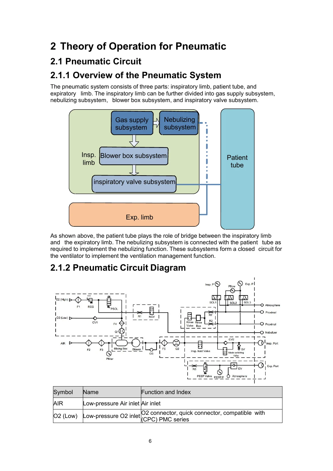
    • Pneumatic Circuit: Detailed diagrams and operation of the gas supply, blower box, inspiratory valve, and expiration assembly subsystems.
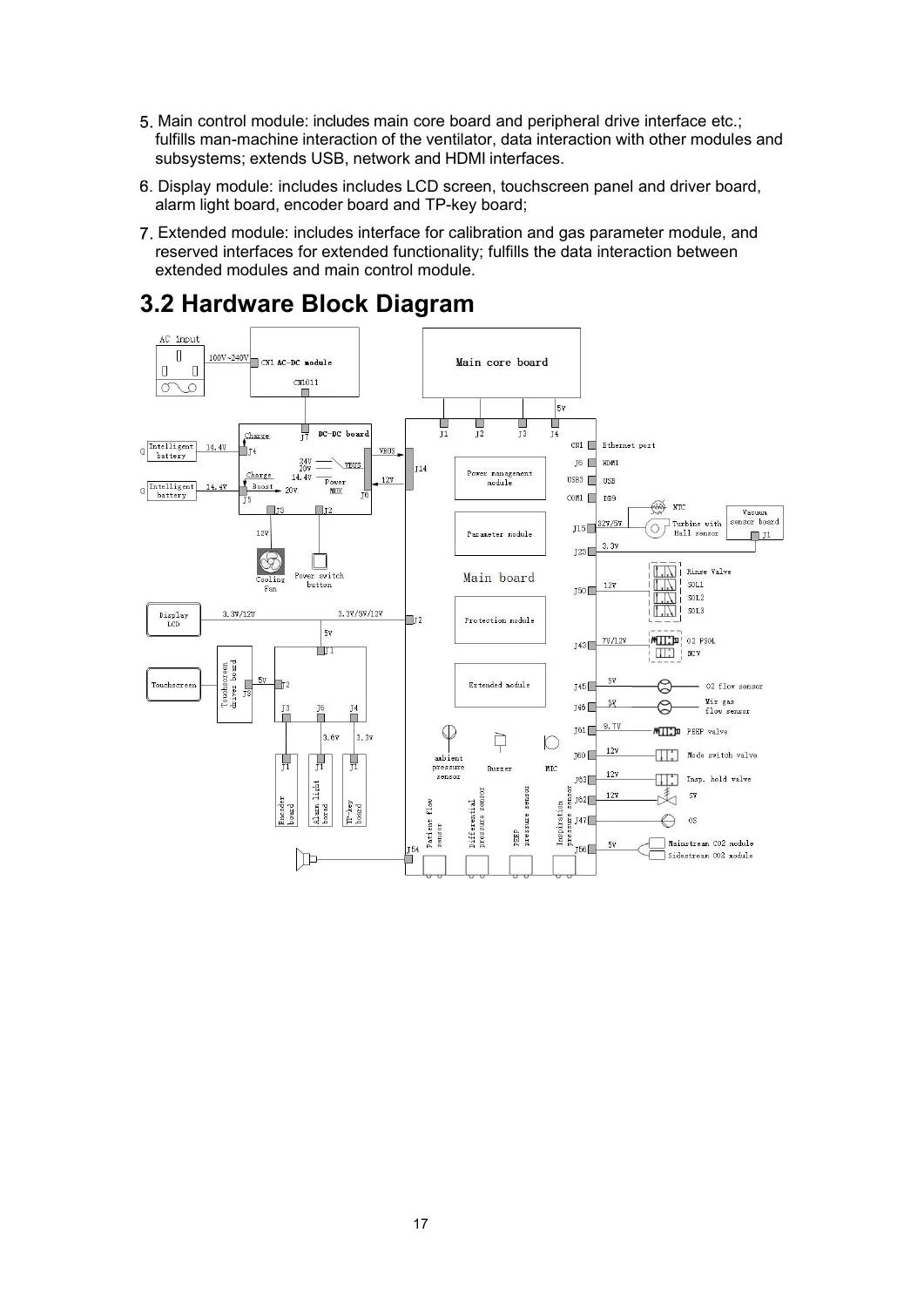
    • Electronic System: Hardware block diagrams, power supply distribution, and detailed descriptions of all board functions (Power, Main, Display).

    IMAGES PREVIEW

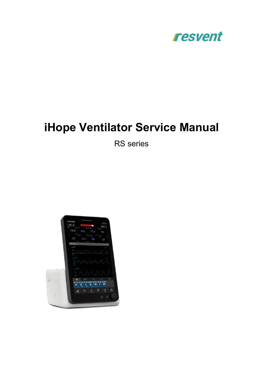
    iHope RS Series Ventilator Service Repair Manual - Download PDF — PDF page 1 preview
    iHope RS Series Ventilator Service Repair Manual - Download PDF — PDF page 13 preview
    iHope RS Series Ventilator Service Repair Manual - Download PDF — PDF page 24 preview

  • Maintenance Menu: Accessing hospital setup, system information, and factory maintenance functions.
  • Software Upgrade: Step-by-step instructions for using a USB memory device to update system software.
  • Preventive Maintenance:
    • One-year and periodic replacement parts schedules (e.g., expiratory valve diaphragm, HEPA filter, lithium battery).
    • Routine test procedures, including system checks and ventilation control tests.
  • Calibration Procedures: Comprehensive instructions for calibrating patient flow, O2%, O2 proportional valve, pressure, and performing pressure/flow zeroing.
  • Troubleshooting:
    • Diagnostic tests for system check failures.
    • Detailed technical alarm troubleshooting with error codes and recommended actions.
    • Pneumatic system failure analysis and resolution.
  • Repair and Disassembly: Detailed, illustrated guides for replacing every major service part, from the inspiratory valve to the power board and turbine component.
  • Performance Verification: A comprehensive suite of tests to ensure the ventilator is functioning correctly after servicing, including alarm tests, function tests, and electrical safety tests.
  • Parts Lists & Exploded Views: Complete diagrams and parts lists for the main unit, display assembly, trolley, and all critical sub-assemblies.

What This Manual Enables You To Do

This service manual is the key to maintaining the iHope RS Series ventilator at the highest level of reliability. It enables technicians to:

Complete PDF Bookmark Tree

Complete Bookmarks

The complete bookmarks in the “iHope RS Series Ventilator Service Repair Manual – Download PDF” are as follows:

1Safetyp. 8
1.1Safety Informationp. 8
1.1.1Definitionsp. 8
1.1.2Warningp. 8
1.1.3Cautionp. 10
1.1.4Notep. 10
1.2Symbolsp. 10
2 Theory of Operation for Pneumaticp. 13
2.1Pneumatic Circuitp. 13
2.1.1Overview of the Pneumatic Systemp. 13
2.1.2Pneumatic Circuit Diagramp. 13
2.1.3Theory of Operation of the Pneumatic Subsystemp. 15
2.1.3.1Gas Supply Subsystemp. 15
2.1.3.2Nebulizing Subsystemp. 17
2.1.3.3Blower Box Subsystemp. 18
2.1.3.4Inspiratory Fixture Seat Subsystemp. 18
2.1.3.5Inspiratory Valve Subsystemp. 19
2.1.3.6Expiration Assemblyp. 19
2.1.3.7Patient Tubep. 20
2.2Pneumatic Connectionp. 21
2.2.1Pneumatic Connection Diagramp. 21
2.2.2Tubes Listp. 21
3 Theory of Operation for Electronicp. 23
3.1System Schematic Diagramp. 23
3.2Hardware Block Diagramp. 24
3.3Power Supply Systemp. 25
3.3.1Power Supply System Blockp. 25
3.3.2Power Supplies Distributionp. 25
3.4Board Functionp. 26
3.4.1Power Boardsp. 26
3.4.1.1AC-DC Modulep. 26
3.4.1.2DC-DC Boardp. 27
3.4.2Main Boardp. 29
3.4.2.1Power Management Modulep. 29
3.4.2.2Main Control Modulep. 30
3.4.2.3Parameter Modulep. 34
3.4.2.4Vacuum Sensor Boardp. 36
3.4.2.5Protection Modulep. 37
3.4.3Display Module Boardsp. 37
3.4.3.1Power Indicator Boardp. 37
3.4.3.2TP-key Boardp. 39
3.4.3.3Alarm Light Boardp. 39
3.4.3.4Encoder Boardp. 40
3.4.3.5Touchscreen Driver Boardp. 40
3.5 Electrical Connectionp. 41
3.5.1Electrical Connection Diagramp. 41
3.5.2Electrical Connection Listp. 41
4Maintenance Menup. 44
4.1Hospital Setupp. 44
4.1.1Languagep. 44
4.1.2Unitp. 44
4.1.3Gas supplyp. 44
4.1.4Defaults settingsp. 44
4.1.5Transfer User Configurationp. 44
4.1.6Export Patient Datap. 45
4.1.7Nurse Call Settingp. 45
4.2System Informationp. 46
4.2.1Version Informationp. 46
4.2.2Configuration Informationp. 46
4.3Factory Maintenancep. 46
4.3.1Factory Setupp. 46
4.3.1.1Settingsp. 46
4.3.1.2Maintenance Informationp. 47
4.3.1.3Functional Activationp. 47
4.3.1.4Restore Factory Defaultsp. 47
4.3.1.5Version Informationp. 49
4.3.2Factory Calibrationp. 49
4.3.3Data Monitoringp. 49
4.3.4Diagnosis Testp. 49
4.3.5Event Logbookp. 49
5 Software Upgradep. 50
5.1Description of USB Memory Upgradep. 50
5.2Problems and Recommended Actionsp. 51
6Preventive Maintenancep. 52
6.1Equipment Maintenancep. 52
6.1.1One-year Replaceable Partsp. 52
6.1.1.1Expiratory valve diaphragm Replacementp. 52
6.1.1.2HEPA filter Replacementp. 53
6.1.1.3Air inlet dust filter Replacementp. 53
6.1.1.4Fan dust filter Replacementp. 53
6.1.2Periodically-Maintained Partsp. 54
6.2Routine Testp. 54
6.2.1System Checkp. 54
6.2.2Ventilation Control testp. 55
6.2.2.1Volume Control Ventilation testp. 56
6.2.2.2Pressure Control Ventilation Testp. 56
6.2.3Sensor Zero Point testp. 57
6.2.4Flow Sensor Accuracy testp. 57
6.2.5Pressure Sensor Accuracy Testp. 58
7Calibrationp. 59
7.1Patient Flow Calibrationp. 60
7.1.1Calibration Proceduresp. 60
7.1.1.1Error Codes and Corrective Actionsp. 61
7.2O2% Calibrationp. 62
7.2.1Calibration Proceduresp. 62
7.2.2Error Codes and Corrective Actionsp. 63
7.3O2 Proportional Valve Calibrationp. 64
7.3.1Calibration Proceduresp. 64
7.3.2Error Codes and Corrective Actionsp. 64
7.4Pressure and Flow Zeroingp. 65
7.4.1Zeroing Proceduresp. 65
7.4.2Error Codes and Corrective Actionsp. 65
7.5Pressure Calibrationp. 67
7.5.1Calibration Proceduresp. 67
7.5.1.1Error Codes and Corrective Actionsp. 70
8 Troubleshootingp. 72
8.1Introductionp. 72
8.2System Check Failuresp. 72
8.3Technical Alarmsp. 74
8.4Diagnostic Testp. 81
8.4.1Preparations for the Testp. 81
8.4.2Troubleshooting Methodsp. 82
8.4.2.1Sensor Zero Point Errorp. 82
8.4.2.2Sensor Sampling Line Connection Errorp. 82
8.4.2.3O2 Proportional Valve Status Errorp. 83
8.4.2.4PEEP Valve Status Errorp. 83
8.4.2.5Pressure release valve Status Errorp. 84
8.5Pneumatic System Failuresp. 84
8.5.1Commonly Used Devices and Toolsp. 84
8.5.2Pneumatic Failures Listp. 85
8.5.3Gas Supply Subsystemp. 87
8.5.3.1Regulator Output Pressure is Inaccuratep. 87
8.5.3.2Nebulizer Is Faulty or Flow is Abnormalp. 88
8.5.3.3Maximum O2 Flow Output Is Smallp. 88
8.5.3.4Measured O2 Flow Fluctuates Greatlyp. 89
8.5.4Maximum Output Flow is Smallp. 89
8.5.5O2 Concentration is Inaccuratep. 89
8.5.6inspiratory Valve Assembly Leakagep. 90
8.5.7Expiration Valve Assembly Leakagep. 90
8.5.8Patient Flow Test has an Errorp. 91
8.5.9O2 Sensor Has Great Measurement Errorp. 91
8.6Hardware and Electrical System Failuresp. 92
9Repair and Disassemblyp. 94
9.1Prepare for Disassemblyp. 94
9.1.1Toolsp. 94
9.1.2Preparationsp. 94
9.2Disassemble the Service Partsp. 95
9.2.1Replace the Inspiratory Valve Componentp. 95
9.2.2Replace the Expiratory Valve Componentp. 95
9.2.3Replace the O2 Sensorp. 95
9.2.4Replace the Air Inlet Dust Filterp. 95
9.2.5Replace the Fan Dust Filterp. 96
9.2.6Replace the HEPA Filterp. 96
9.2.7Replace the Upper Cover Componentp. 96
9.2.8Replace the Display Componentp. 97
9.2.9Replace the Side Coverp. 98
9.2.10Replace the Lithium Batteryp. 99
9.2.11Replace the Core-Board PCBAp. 99
9.2.12Replace the Main Board PCBAp. 100
9.2.13Replace the Front Bafflep. 101
9.2.14Replace the Three-way Valvep. 102
9.2.15Replace the Gas Capacitor Componentp. 102
9.2.16Replace the Power Boardp. 102
9.2.17Replace the Turbine Componentp. 102
9.2.18Replace the Inspiratory Valve Seat Componentp. 104
9.2.19Replace the O2 Inlet Componentp. 104
9.2.20Replace the Right Panelp. 105
9.2.21Replace the Expiratory Valve Seat Componentp. 105
9.2.22Replace the Speakerp. 105
9.2.23Replace the AC-DC Power Modulep. 106
9.2.24Replace the Fanp. 106
9.2.25Replace the Switchp. 106
10Performance Verificationp. 108
10.1System Inspectionp. 108
10.2Power Failure Alarm Testp. 108
10.3O2 Pipeline Testp. 108
10.4System Testp. 109
10.5Spontaneous Breathing Supporting Testp. 109
10.6Humidifier Performance Testp. 109
10.7Alarm Testsp. 109
10.7.1Prepare for Alarm Testsp. 109
10.7.2High Pressure Testp. 110
10.7.3High Tidal Volume Testp. 110
10.7.4Low Tidal Volume Testp. 110
10.7.5Low Minute Volume Testp. 110
10.7.6High PEEP Testp. 110
10.7.7Patient Circuit Occluded Testp. 111
10.7.8High Oxygen Testp. 111
10.7.9Low Oxygen Testp. 111
10.7.10Running on Internal Battery Testp. 111
10.7.11Battery Low Testp. 111
10.7.12Apnea Alarm Testp. 112
10.8Function Testsp. 112
10.8.1Setting to Standard Working Modep. 112
10.8.2Tidal Volume testp. 112
10.8.3Trigger Function Testp. 112
10.8.4Special Functions Testp. 112
10.9Electrical Safety testp. 113
10.9.1Test methodp. 113
10.9.2test Formp. 114
11Partsp. 115
11.1Main Unit Assemblyp. 115
11.1.1Exploded Viewp. 115
11.1.2Parts Listp. 115
11.2Display Assemblyp. 116
11.2.1Exploded Viewp. 116
11.2.2Parts Listp. 116
11.3Display Front Housing Assemblyp. 117
11.3.1Exploded Viewp. 117
11.3.2Parts Listp. 117
11.4Kernel Assemblyp. 118
11.4.1Exploded Viewp. 118
11.4.2Parts Listp. 118
11.5 O2 Inlet Assembly(NIST)p. 119
11.5.1Exploded Viewp. 119
11.5.2Parts Listp. 119
11.6O2 Inlet Assembly(DISS)p. 120
11.6.1Exploded Viewp. 120
11.6.2Parts Listp. 120
11.7Blower Box Assemblyp. 121
11.7.1Exploded Viewp. 121
11.7.2Parts Listp. 121
11.8Insp. Valve Seat Assemblyp. 121
11.8.1Exploded Viewp. 121
11.8.2Parts Listp. 121
11.9 Insp. Valve Assemblyp. 122
11.9.1Exploded Viewp. 122
11.9.2Parts Listp. 122
11.10Exp. Valve Seat Assemblyp. 123
11.10.1Exploded Viewp. 123
11.10.2Parts Listp. 123
11.11Exp. Valve Assembly for adultp. 123
11.11.1Exploded Viewp. 123
11.11.2Parts Listp. 123
11.12 Exp. Valve Assembly for infantp. 124
11.12.1Exploded Viewp. 124
11.12.2Parts Listp. 124
11.13Rinse box Assemblyp. 124
11.13.1Exploded Viewp. 124
11.13.2Parts Listp. 124
11.14 Trolley Assemblyp. 125
11.14.1Exploded Viewp. 125
11.14.2Parts Listp. 125
11.15Trolley Handle Assemblyp. 126
11.15.1Exploded Viewp. 126
11.15.2Parts Listp. 126
11.16 Trolley Base Assemblyp. 127
11.16.1Exploded Viewp. 127
11.16.2Parts Listp. 127
11.17Trolley Gas Cylinder Fixed Assemblyp. 128
11.17.1Exploded Viewp. 128
11.17.2Parts Listp. 128
A Preventive Maintenance Reportp. 129
A.1 Check before Preventive Maintenancep. 129
A.2 Preventive Maintenancep. 129
A.3 Test after Preventive Maintenancep. 130
B Replacement Parts Listp. 133

  • Diagnose and correct complex technical alarms and system errors.
  • Perform precise calibration of flow, pressure, and oxygen sensors to guarantee accurate patient ventilation.
  • Execute scheduled preventive maintenance, including the replacement of critical wear parts like filters and diaphragms.
  • Safely disassemble, repair, and reassemble the ventilator’s pneumatic and electronic modules.
  • Verify complete system performance and electrical safety after any repair or service action.

Having this manual ensures that service personnel can work efficiently and safely, minimizing ventilator downtime and helping to ensure patient safety. It contains the exact procedures, specifications, and diagrams provided by Resvent to their certified service networks.

Instant Download

Upon completion of your purchase, you will receive an instant link to download the PDF file. This digital format allows you to access the manual immediately from any device, print specific pages for use in the workshop, or keep a digital reference on your tablet or laptop.


Reviews

There are no reviews yet.

Be the first to review “iHope RS Series Ventilator Service Repair Manual – Download PDF”

What Our Customers Say

★★★★★ Live reviews from customers
Loading customer reviews...
0
    0
    Your Cart
    Your cart is emptyReturn to Shop
    🛒
    Recently Purchased
    🕒 verified order