★ TRUSTED BY 321,897+ PROFESSIONALS WORLDWIDE
🏢
Trusted Business
Verified & Licensed
🛡️
Virus Free Files
100% Safe Downloads
🔒
Secure Payment
SSL Protected
Instant Delivery
Available Immediately
Sale!

Skyjack SJ63AJ Articulating Boom Lift Service Manual 194314AN 2023

Original price was: $39.95.Current price is: $24.95.

Complete 342-page Skyjack SJ63AJ Articulating Boom service manual (194314AN, 2023). Covers maintenance schedules, troubleshooting, hydraulic and electrical schematics, torque specs, and step-by-step repair procedures for Deutz, Perkins, Kubota and GM engine variants.

Instant PDF Download
Available immediately
💾
Save to Your Device
Download & keep forever
🛡️
Antivirus Scanned
100% virus-free
🌍
Trusted Worldwide
175,000+ customers

Description

Skyjack SJ63AJ Articulating Boom Service Manual — 194314AN (2023)

This is the full 342-page Skyjack SJ63AJ Articulating Boom service manual, document number 194314AN, published in 2023. It is the workshop-level reference used by technicians to maintain, diagnose, and repair the SJ63AJ articulating boom lift — from scheduled inspection intervals through hydraulic valve adjustments, engine fault-code retrieval, boom section removal, and axle brake inspection. Every section is indexed, illustrated, and written around the actual machine, not a generic boom-lift template.

File Details

  • Manual Type: Service Manual
  • Brand: Skyjack
  • Model: SJ63AJ Articulating Boom
  • Document Number: 194314AN
  • Publication Year: 2023
  • Language: English
  • Page Count: 342
  • File Format: PDF

What This Skyjack SJ63AJ Service Manual Covers

The manual is divided into five major sections, each building on the last — scheduled maintenance first, then the reference tables, then the component and schematic identification, then the troubleshooting trees, and finally the hands-on procedures. Together they give a technician everything needed to keep an SJ63AJ running to specification.

Chapters Covered

  • Section 1 — Scheduled Maintenance
    • Read and Heed — MEWP definition, purpose, use, manual, service policy and warranty
    • Maintenance and Service — schedules, owner’s annual inspection record, replacement parts, safety tips
    • Hydraulic System & Component Maintenance and Repair
    • Hydraulic Maintenance Hints
    • Railing Maintenance and Repair
    • Scheduled Maintenance — service bulletins, maintenance and inspection, instructions
    • Pre-Delivery / Maintenance Inspection Checklist
    • Scheduled Maintenance Inspections — electrical, hydraulic, manuals, labels, limit switches, engine compartment, control compartment, base, platform assembly, boom assembly
    • Function Tests
  • Section 2 — Maintenance Tables and Diagrams
    • Standard Hose Numbering System
    • Torque Specifications for Fasteners (US Imperial and Metric)
    • Torque Specifications for Hydraulic Couplings & Hoses
    • Axle Torque Specifications and Axles Maintenance Intervals
    • MEWP Torque Specifications
    • Maximum Platform Capacity, Tire Specifications, Floor Loading Pressure
    • Hydraulic Specifications & Gear Oil
    • Specifications & Features — Dimensions & Speeds
    • Engine Specifications
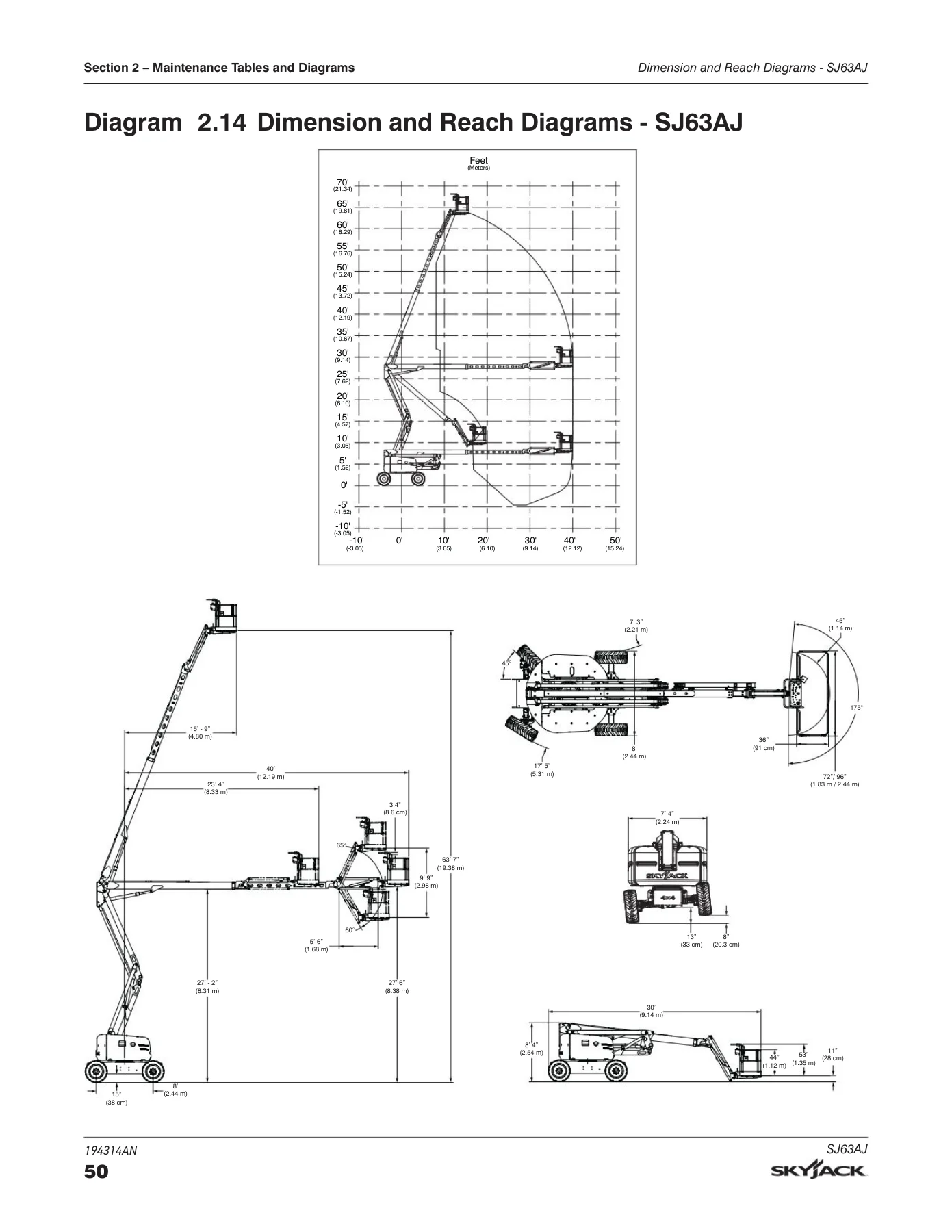
    • Dimension and Reach Diagrams — SJ63AJ
    • Axle Oscillation Diagrams
  • Section 3 — System Component Identification and Schematics
    • Electrical Symbol Chart and Hydraulic Symbol Chart
    • Wire Number and Color Code
    • Hydraulic Parts List and Electrical Component Parts List
    • Rotary Manifold, Brake Manifold, Drive and System Pump, Drive Motor, Jib Valve, Main Manifold port identifications
    • Main Electrical Harness and Fuel Level Switch Harness
    • ECU Engine Wiring Diagram — Deutz; Glow Plug Harnesses — Deutz D2011 and TD2.9L
    • Engine Interface Harness — GM, Deutz TD2.9L, Perkins 2.2TA, Deutz TCD2.2
    • Lowering Throttle Valve Harness, Platform Harnesses, Platform Control Cables
    • Limit Switch Connections at the Base Control Box
    • Load Sensing Connections — CE & AS; All Motion Alarm Connections — CE & AS
    • SGE Schematics and SGE Platform Control Wiring Diagram
    • Hydraulic Generator and Oil Cooler Wiring — Base Control Box
    • Generator Wiring — Upper Control Box; Welder Wiring — ANSI/CSA; Load Circuit Wiring
    • Positive Air Shutoff Harness
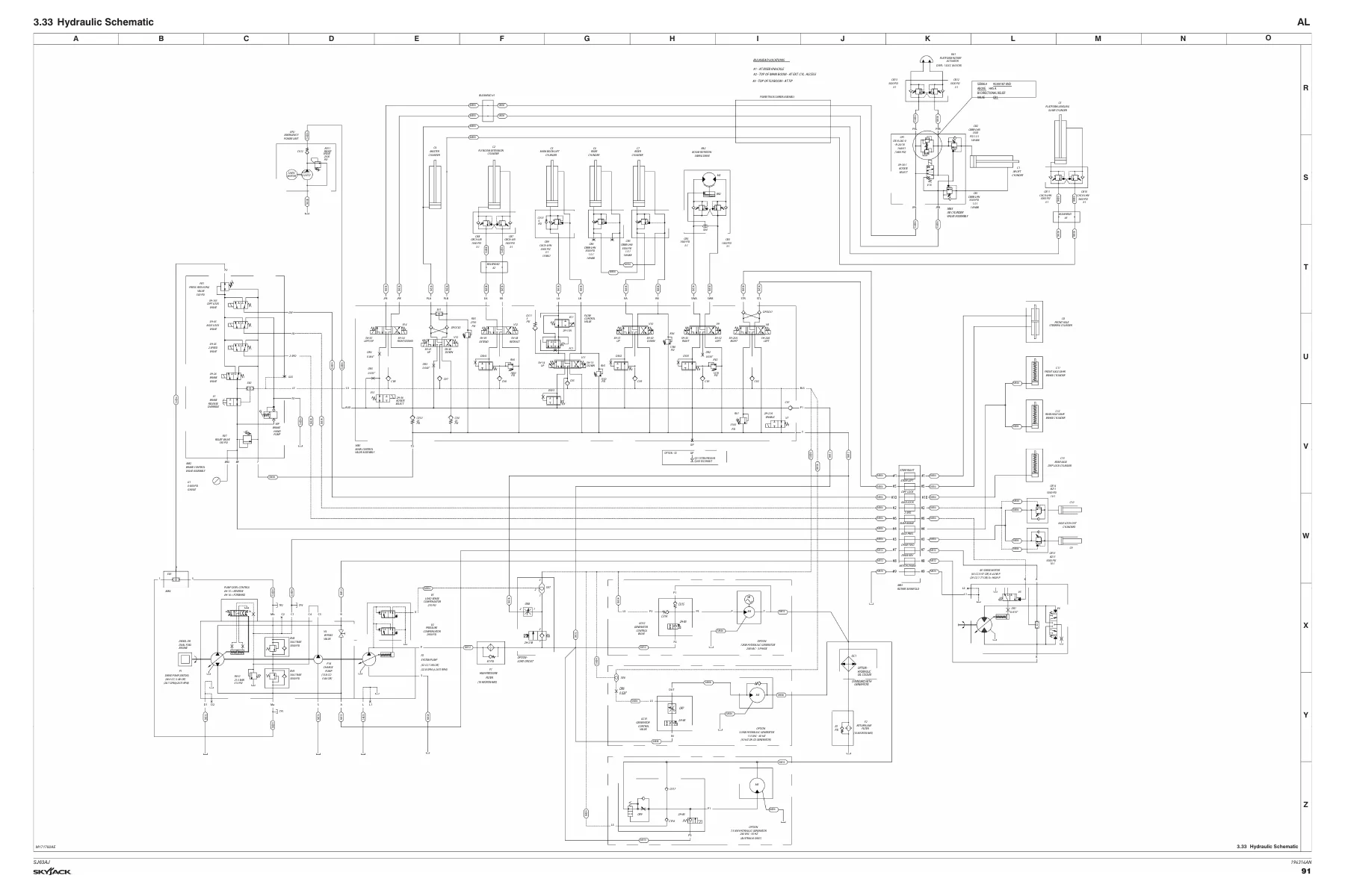
    • Hydraulic Schematic
    • Platform Control Box Wiring — ANSI/CSA, CE, AS (GM, Kubota, Deutz variants)
    • Base Control Box Wiring — ANSI/CSA, CE, AS (GM, Deutz TD2.9L, Deutz D2011, Perkins 2.2TA, Kubota WG2503)
    • Electrical Schematics — ANSI/CSA, CE, AS (multiple engine and serial ranges)
    • Engine Electrical Schematics — GM, Kubota WG2503, Deutz TD2.9L, Deutz TCD2.2
    • Engine Interface Harness and OEM / Component Harness — Perkins 2.2TA
  • Section 4 — Troubleshooting Information
    • Electrical System (ANSI/CSA) — from “All Controls Inoperative” through drive, steer, throttle, and direction-sensing faults
    • Electrical System (CE & AS) — equivalent fault trees for CE and AS variants
    • Hydraulic System (ANSI/CSA) — boom, riser, turret, jib, platform level, brake, differential, axle and steer faults
    • Hydraulic System (CE & AS)
    • Load Sensing System (CE) — LED diagnostics, alarm behaviour, calibration verification
  • Section 5 — Procedures
    • General — Safety and Workmanship
    • Platform — HMI, OCM character functions, operating values, functionality selection, OCM unlock and modification, pin voltage references, controller voltage references
    • Boom — wear pads, cable carrier repair, rotary actuator bolt torque, boom section wear pad replacement, platform and jib boom removal, fly boom removal and installation, extension cylinder removal and installation, main boom lift cylinder, riser cylinder, limit switch locations and replacement
    • Turret — high pressure filter, turret rotation gear backlash, swing drive motor removal, swing drive oil, rotation bearing axial wear, turret rotation gear bolt torque, electronic tilt switch setup, battery replacement
    • Deutz Diesel Engine — engine oil and filter, fuel filter, air filter, engine belt, oil cooler (D2011), engine fault code retrieval and full TD2.9L fault code list
    • Kubota WG2503 Dual Fuel Engine — KAntrak 1700 parameter display, diagnostic trouble codes, ECU pin reference, fuse box, MAP sensor, IAT sensor, ECT, TPS & engine speed, fuel temperature sensor, oil pressure sensor
    • Hydraulic Tank — tank filter change, hydraulic oil change
    • Manifold and Hydraulic Pumps — brake pressure adjustment, system relief RV1, turret rotate RV2, platform level RV3, riser down RV4, main boom down RV5, fly boom RV6, charge pump pressure, forward and reverse drive pressure, standby pressure, high pressure adjustment
    • Axles — axle oil, torque hub oil check and change, axle gearbox oil check and change, oscillating cylinder bolt replacement and cylinder replacement, bleeding the oscillating axle cylinders, pin brake adjustments, brake inspection
    • Grease Points — turret ring gear, turret swing drive, axles, drive shaft
    • Load Sensing System — overload status, verification of operation, calibration with “Teach In” handset
    • Generator — troubleshooting, frequency/voltage check and adjustment

    Complete PDF Bookmark Tree

    Complete Bookmarks

    The complete bookmarks in the “Skyjack SJ63AJ Articulating Boom Lift Service Manual 194314AN 2023” are as follows:

    Table of Contentsp. 5
    Section 1 – Scheduled Maintenancep. 17
    1.1 Read and Heedp. 17
    1.1-1 Mobile Elevating Work Platform (MEWP) Definitionp. 17
    1.1-2 Purpose of Equipmentp. 17
    1.1-3 Use of Equipmentp. 17
    1.1-4 Manualp. 17
    1.1-5 Service Policy and Warrantyp. 17
    1.1-6 Operator Safety Reminders, Warnings and Precautionsp. 17
    1.2 Maintenance and Servicep. 18
    1.2-1 Maintenance and Inspection Schedulep. 18
    1.2-2 Owner’s Annual Inspection Recordp. 18
    1.2-3 Replacement Partsp. 18
    1.2-4 Maintenance and Service Safety Tipsp. 18
    1.2-5 Hydraulic System & Component Maintenance and Repairp. 19
    1.2-6 Hydraulic Maintenance Hintsp. 19
    1.2-7 Railing Maintenance and Repairp. 20
    1.3 Scheduled Maintenancep. 21
    1.3-1 Service Bulletinsp. 21
    1.3-2 Maintenance and Inspectionp. 21
    1.3-3 Maintenance Instructionsp. 21
    1.4 Owner’s Annual Inspection Recordp. 22
    1.5 Pre-Delivery/Maintenance Inspection Checklistp. 23
    1.6 Scheduled Maintenance Inspectionsp. 24
    1.6-1 Electricalp. 24
    1.6-2 Hydraulicp. 24
    1.6-3 Manuals & Required Documents (B)p. 24
    1.6-4 Labels (B)p. 24
    1.6-5 Limit Switches (B)p. 25
    1.6-6 Engine Compartmentp. 25
    1.6-7 Control Compartmentp. 28
    1.6-8 Basep. 30
    1.6-9 Platform Assemblyp. 32
    1.6-10 Boom Assemblyp. 33
    1.7 Function Testsp. 34
    Section 2 – Maintenance Tables and Diagramsp. 35
    2.1 Standard Hose Numbering Systemp. 35
    2.2 Torque Specifications for Fasteners (US Imperial)p. 37
    2.3 Torque Specifications for Fasteners (Metric)p. 38
    2.4 Torque Specifications for Hydraulic Couplings & Hosesp. 39
    2.5 Axle Torque Specificationsp. 40
    2.6 Axles Maintenance Intervalsp. 41
    2.7 MEWP Torque Specificationsp. 42
    2.8 Maximum Platform Capacityp. 43
    2.9 Tire Specificationsp. 43
    2.10 Floor Loading Pressurep. 44
    2.11 Hydraulic Specifications & Gear Oilp. 45
    2.12 Specifications & Features – Dimensions & Speedsp. 46
    2.13 Engine Specificationsp. 48
    2.14 Dimension and Reach Diagrams – SJ63AJp. 50
    2.15 Axle Oscillation Diagramsp. 51
    Section 3 – System Component Identification and Schematicsp. 53
    3.1 Electrical Symbol Chartp. 54
    3.2 Hydraulic Symbol Chartp. 55
    3.3 Wire Number and Color Codep. 56
    3.4 Hydraulic Parts Listp. 57
    3.5 Electrical Component Parts Listp. 61
    3.6 Rotary Manifold Port Identificationp. 64
    3.7 Brake Manifold Port Identificationp. 65
    3.8 Drive and System Pump and Port Identificationsp. 66
    3.9 Drive Motor and Port Identificationsp. 67
    3.10 Jib Valve and Port Identificationsp. 68
    3.11 Main Manifold and Port Identificationsp. 69
    3.12 Main Manifold and Electrical Identificationsp. 70
    3.13 Main Manifold and Hydraulic Identificationsp. 71
    3.14 Main Electrical Harness and Fuel Level Switch Harnessp. 72
    3.15 ECU Engine Wiring Diagram – Deutzp. 73
    3.16 Glow Plug Harnesses – Deutz D2011p. 74
    3.17 Glow Plug Harnesses – Deutz TD2.9Lp. 75
    3.18 Engine Interface Harness – GMp. 76
    3.19 Engine Interface Harness – Deutz TD2.9Lp. 77
    3.20 Lowering Throttle Valve Harnessp. 78
    3.21 Platform Harnessesp. 79
    3.22 Platform Control Cablesp. 80
    3.23 Limit Switch Connections at the Base Control Boxp. 81
    3.24 Load Sensing Connections – CE & ASp. 82
    3.25 All Motion Alarm Connections – CE & ASp. 83
    3.26 SGE Schematicsp. 84
    3.27 SGE Platform Control Wiring Diagramp. 85
    3.28 Hydraulic Generator and Oil Cooler Wiring – Base Control Boxp. 86
    3.29 Generator Wiring – Upper Control Boxp. 87
    3.30 Welder Wiring – ANSI/CSAp. 88
    3.31 Load Circuit Wiringp. 89
    3.32 Positive Air Shutoff Harnessp. 90
    3.33 Hydraulic Schematicp. 91
    3.34 Platform Control Box Wiring – ANSI/CSA – GM & Kubotap. 92
    3.35 Platform Control Box Wiring – ANSI/CSA – Deutzp. 93
    3.36 Platform Conrol Box Wiring – CE – Deutz TCD2.2p. 94
    3.37 Platform Control Box Wiring – CE – Deutz TD2.9L & D2011p. 95
    3.38 Platform Control Box Wiring – CE – Kubota WG2503p. 96
    3.39 Platform Control Box Wiring – AS – Deutzp. 97
    3.40 Base Control Box Wiring – ANSI/CSA – GMp. 98
    3.41 Base Control Box Wiring – ANSI/CSA – Deutz TD2.9Lp. 99
    3.42 Base Control Box Wiring – ANSI/CSA – Deutz TD2.9L with Positive Air Shutoff Optionp. 100
    3.43 Base Control Box Wiring – ANSI/CSA – Deutz D2011p. 101
    3.44 Base Control Box Wiring – ANSI/CSA – Deutz D2011 with Positive Air Shut-Offp. 102
    3.45 Base Control Box Wiring – Perkins 2.2TAp. 103
    3.46 Base Control Box Wiring – CE – Deutz TCD2.2p. 104
    3.47 Base Control Box Wiring – CE – Deutz TD2.9Lp. 105
    3.48 Base Control Box Wiring – CE – Deutz D2011p. 106
    3.49 Base Control Box Wiring – CE – Kubota WG2503p. 107
    3.50 Base Control Box Wiring – AS – Deutz D2011p. 108
    3.51 Electrical Schematic – ANSI/CSA – GMp. 109
    3.52 Electrical Schematic – ANSI/CSA – Kubota WG2503 (S/N 95301738 and below)p. 110
    3.53 Electrical Schematic – ANSI/CSA – Kubota WG2503 (S/N 95301739 and above)p. 111
    3.54 Electrical Schematic – ANSI/CSA – Deutz TD2.9L (S/N 95301738 and below)p. 112
    3.55 Electrical Schematic – ANSI/CSA – Deutz TD2.9L (S/N 95301739 and above)p. 113
    3.56 Electrical Schematic – ANSI/CSA – Deutz D2011 (S/N 95301738 and below)p. 114
    3.57 Electrical Schematic – ANSI/CSA – Deutz D2011 (S/N 95301739 and above)p. 115
    3.58 Electrical Schematic – ANSI/CSA – Perkins 2.2TA (S/N 95301738 and below)p. 116
    3.59 Electrical Schematic – ANSI/CSA – Perkins 2.2TA (S/N 95301739 and above)p. 117
    3.60 Electrical Schematic – CE – Deutz TCD2.2p. 118
    3.61 Electrical Schematic – CE – Deutz TD2.9L Diesel (S/N 95301738 and below)p. 119
    3.62 Electrical Schematic – CE – Deutz TD2.9L Diesel (S/N 95301739 and above)p. 120
    3.63 Electrical Schematic – CE – Deutz D2011 (S/N 95301738 and below)p. 121
    3.64 Electrical Schematic – CE – Deutz D2011 (S/N 95301739 and above)p. 122
    3.65 Electrical Schematic – CE – Kubota WG2503 (S/N 9530178 and below)p. 123
    3.66 Electrical Schematic – CE – Kubota WG2503 (S/N 9530179 and above)p. 124
    3.67 Electrical Schematic – AS – Deutz D2011 (S/N 95301738 and below)p. 125
    3.68 Electrical Schematic – AS – Deutz D2011 (S/N 95301739 and above)p. 126
    3.69 Engine Electrical Schematic – GMp. 127
    3.70 Engine Electrical Schematic – Kubota WG2503p. 128
    3.71 Engine Electrical Schematic – CE – Kubota WG2503p. 129
    3.72 Engine Electrical Schematic – Deutz TD2.9Lp. 130
    3.73 Engine Electrical Schematic – CE – Deutz TD2.9L Dieselp. 131
    3.74 Engine Interface Wiring – Deutz TD2.9Lp. 132
    3.75 Engine Interface Harness – Perkins 2.2TAp. 133
    3.76 Engine OEM Harness – Perkins 2.2TAp. 134
    3.77 Engine Component Harness – Perkins 2.2TAp. 135
    3.78 Engine Electrical Schematic – Deutz TCD2.2p. 136
    3.79 Engine Interface Harness – Deutz TCD2.2p. 137
    Section 4 – Troubleshooting Informationp. 139
    4.1 Introductionp. 139
    4.2 Electrical System (ANSI/CSA)p. 140
    4.2-1 All Controls Inoperativep. 140
    4.2-2 No Power To Platformp. 141
    4.2-3 No Power to Basep. 141
    4.2-4 Engine Will Not Crank from Basep. 142
    4.2-5 Engine Will Not Crank from Platformp. 142
    4.2-6 Engine Will Not Crank from Platform or Base (Deutz TD2.9L)p. 142
    4.2-7 Engine Will Not Crank from Platform or Base when equipped with Elevate/Trackunit Telematics Readyp. 143
    4.2-8 Engine Cranks but Will Not Start (Deutz TD2.9L)p. 144
    4.2-9 Engine Cranks but Will Not Start (Deutz D2011)p. 144
    4.2-10 Engine Will Not Crank from Platform or Base (Deutz Diesel D2011)p. 145
    4.2-11 Engine Cranks but Will Not Start (Deutz Diesel D2011)p. 146
    4.2-12 Engine Will Not Crank from Platform or Base Control (GM Dual Fuel)p. 146
    4.2-13 Engine Cranks but Will Not Start (GM Dual Fuel)p. 147
    4.2-14 Fuel Related Problems (Gasoline only)p. 148
    4.2-15 Fuel Related Problems (Propane only)p. 149
    4.2-16 Glow Plug Circuit Inoperativep. 149
    4.2-17 All Controls Inoperative from Base Consolep. 150
    4.2-18 No Main Boom Down, Riser Down or Turret Rotate from Base Control Consolep. 151
    4.2-19 No Boom Up from Base Control Consolep. 151
    4.2-20 No Boom Down from Base Control Consolep. 152
    4.2-21 No Riser Up from Base Control Consolep. 152
    4.2-22 No Riser Down from Base Control Consolep. 153
    4.2-23 No Turret Rotate Left from Base Control Consolep. 153
    4.2-24 No Turret Rotate Right from Base Control Consolep. 154
    4.2-25 No Telescope Retract from Base Control Consolep. 154
    4.2-26 No Telescope Extend from Base Control Consolep. 155
    4.2-27 No Platform Rotate Left or Rightp. 155
    4.2-28 Platform Rotates too Quicklyp. 156
    4.2-29 No Platform Rotate Left from Base Control Consolep. 156
    4.2-30 No Platform Rotate Right from Base Control Consolep. 157
    4.2-31 No Jib Up from Base Control Consolep. 158
    4.2-32 No Jib Down from Base Control Consolep. 158
    4.2-33 No Manual Platform Level Up from Base Control Consolep. 159
    4.2-34 No Manual Platform Level Down from Base Control Consolep. 159
    4.2-35 All Controls Inoperative from Platform Control Consolep. 160
    4.2-36 No Boom Up from Platform Control Consolep. 161
    4.2-37 No Boom Down from Platform Control Consolep. 162
    4.2-38 No Riser Up from Platform Control Consolep. 162
    4.2-39 No Riser Down from Platform Control Consolep. 163
    4.2-40 No Turret Left from Platform Control Consolep. 164
    4.2-41 No Turret Right from Platform Control Consolep. 165
    4.2-42 No Toggle Switch Functions from Platform Control Consolep. 166
    4.2-43 No Telescope In from Platform Control Consolep. 166
    4.2-44 No Telescope Out from Platform Control Consolep. 167
    4.2-45 No Platform Rotate Left from Platform Control Consolep. 167
    4.2-46 No Platform Rotate Right from Platform Control Consolep. 169
    4.2-47 No Jib Up from Platform Control Consolep. 170
    4.2-48 No Jib Down from Platform Control Consolep. 171
    4.2-49 No Manual Platform Level Up from Platform Control Consolep. 172
    4.2-50 No Manual Platform Level Down from Platform Control Consolep. 173
    4.2-51 Throttle Inoperative, Mid and High (Deutz TD2.9L only)p. 174
    4.2-52 Mid Throttle Inoperativep. 174
    4.2-53 High Throttle Inoperativep. 175
    4.2-54 Differential Lock will not Engagep. 177
    4.2-55 Differential Lock Engages Momentarily but will not stay Engagedp. 177
    4.2-56 No Drive and Steerp. 178
    4.2-57 No Forward Drivep. 178
    4.2-58 No Reverse Drivep. 179
    4.2-59 No High Speed Drivep. 179
    4.2-60 No Elevated Drivep. 181
    4.2-61 No Left Steerp. 181
    4.2-62 No Right Steerp. 182
    4.2-63 Direction Sensing Inoperativep. 182
    4.3 Electrical System (CE & AS)p. 183
    4.3-1 All Controls Inoperativep. 183
    4.3-2 No Power To Platformp. 184
    4.3-3 No Power to Basep. 184
    4.3-4 Engine Will Not Crank from Basep. 185
    4.3-5 Engine Will Not Crank from Platformp. 185
    4.3-6 Engine Will Not Crank from Platform or Base (Deutz Diesel)p. 185
    4.3-7 Engine Will Not Crank from Platform or Base when equipped with Elevate/Trackunit Telematics Readyp. 186
    4.3-8 Engine Cranks but Will Not Start (Deutz Diesel)p. 187
    4.3-9 Engine Will Not Crank from Platform or Base Control (GM Dual Fuel)p. 187
    4.3-10 Engine Cranks but Will Not Start (GM Dual Fuel)p. 188
    4.3-11 Glow Plug Circuit Inoperativep. 190
    4.3-12 All Controls Inoperative from Base Consolep. 191
    4.3-13 No Main Boom Down, Riser Down or Turret Rotate from Base Control Consolep. 192
    4.3-14 No Boom Up from Base Control Consolep. 192
    4.3-15 No Boom Down from Base Control Consolep. 193
    4.3-16 No Riser Up from Base Control Consolep. 193
    4.3-17 No Riser Down from Base Control Consolep. 194
    4.3-18 No Turret Rotate Left from Base Control Consolep. 194
    4.3-19 No Turret Rotate Right from Base Control Consolep. 195
    4.3-20 No Telescope Retract from Base Control Consolep. 195
    4.3-21 No Telescope Extend from Base Control Consolep. 196
    4.3-22 No Platform Rotate Left or Rightp. 196
    4.3-23 Platform Rotates too Quicklyp. 197
    4.3-24 No Platform Rotate Left from Base Control Consolep. 197
    4.3-25 No Platform Rotate Right from Base Control Consolep. 198
    4.3-26 No Jib Up from Base Control Consolep. 199
    4.3-27 No Jib Down from Base Control Consolep. 199
    4.3-28 No Manual Platform Level Up from Base Control Consolep. 200
    4.3-29 No Manual Platform Level Down from Base Control Consolep. 200
    4.3-30 All Controls Inoperative from Platform Control Consolep. 200
    4.3-31 No Boom Up from Platform Control Consolep. 202
    4.3-32 No Boom Down from Platform Control Consolep. 202
    4.3-33 No Riser Up from Platform Control Consolep. 203
    4.3-34 No Riser Down from Platform Control Consolep. 204
    4.3-35 No Turret Left from Platform Control Consolep. 205
    4.3-36 No Turret Right from Platform Control Consolep. 205
    4.3-37 No Toggle Switch Functions from Platform Control Consolep. 206
    4.3-38 No Telescope In from Platform Control Consolep. 206
    4.3-39 No Telescope Out from Platform Control Consolep. 207
    4.3-40 No Platform Rotate Left from Platform Control Consolep. 208
    4.3-41 No Platform Rotate Right from Platform Control Consolep. 209
    4.3-42 No Jib Up from Platform Control Consolep. 210
    4.3-43 No Jib Down from Platform Control Consolep. 211
    4.3-44 No Manual Platform Level Up from Platform Control Consolep. 212
    4.3-45 No Manual Platform Level Down from Platform Control Consolep. 213
    4.3-46 Mid Throttle Inoperativep. 214
    4.3-47 High Throttle Inoperativep. 215
    4.3-48 Brake will not Releasep. 216
    4.3-49 Differential Lock will not Engagep. 216
    4.3-50 Differential Lock Engages Momentarily but will not stay Engagedp. 217
    4.3-51 No Drive and Steerp. 217
    4.3-52 No Forward Drivep. 218
    4.3-53 No Reverse Drivep. 218
    4.3-54 No High Speed Drivep. 219
    4.3-55 No Elevated Drivep. 220
    4.3-56 No Left Steerp. 221
    4.3-57 No Right Steerp. 221
    4.3-58 Direction Sensing Inoperativep. 222
    4.4 Hydraulic System (ANSI/CSA)p. 223
    4.4-1 All Controls Inoperativep. 223
    4.4-2 All Boom Functions Inoperativep. 223
    4.4-3 No Main Boom Upp. 223
    4.4-4 No Main Boom Downp. 223
    4.4-5 No Riser Boom Upp. 224
    4.4-6 No Riser Boom Downp. 224
    4.4-7 No Turret Rotate Leftp. 225
    4.4-8 No Turret Rotate Rightp. 225
    4.4-9 No Boom Extendp. 226
    4.4-10 No Boom Retractp. 226
    4.4-11 No Jib Upp. 226
    4.4-12 Jib Up/ Down Slowp. 227
    4.4-13 No Jib Downp. 227
    4.4-14 No Platform Rotation Rightp. 227
    4.4-15 No Platform Rotation Leftp. 227
    4.4-16 Platform Rotates too Quicklyp. 228
    4.4-17 Platform will not Level Down Manuallyp. 228
    4.4-18 Platform will not Level Up Manuallyp. 228
    4.4-19 Brake will not Releasep. 229
    4.4-20 Brake will not Engagep. 229
    4.4-21 Differential Lock will not Engagep. 230
    4.4-22 No Drive Forward or Reversep. 230
    4.4-23 No Forward Drivep. 230
    4.4-24 No Reverse Drivep. 230
    4.4-25 No High Speed Drivep. 231
    4.4-26 No Right Steerp. 231
    4.4-27 No Left Steerp. 231
    4.4-28 Axle Will Not Oscillatep. 232
    4.4-29 Axle Will Not Lockp. 232
    4.5 Hydraulic System (CE & AS)p. 233
    4.5-1 All Controls Inoperativep. 233
    4.5-2 All Boom Functions Inoperativep. 233
    4.5-3 No Main Boom Upp. 233
    4.5-4 No Main Boom Downp. 233
    4.5-5 No Riser Boom Upp. 234
    4.5-6 No Riser Boom Downp. 234
    4.5-7 No Turret Rotate Leftp. 235
    4.5-8 No Turret Rotate Rightp. 235
    4.5-9 No Boom Extendp. 236
    4.5-10 No Boom Retractp. 236
    4.5-11 No Jib Upp. 236
    4.5-12 Jib Up/ Down Slowp. 237
    4.5-13 No Jib Downp. 237
    4.5-14 No Platform Rotation Rightp. 237
    4.5-15 No Platform Rotation Leftp. 237
    4.5-16 Platform Rotates too Quicklyp. 238
    4.5-17 Platform will not Level Down Manuallyp. 238
    4.5-18 Platform will not Level Up Manuallyp. 238
    4.5-19 Brake will not Releasep. 239
    4.5-20 Brake will not Engagep. 239
    4.5-21 Differential Lock will not Engagep. 240
    4.5-22 No Drive Forward or Reversep. 240
    4.5-23 No Forward Drivep. 240
    4.5-24 No Reverse Drivep. 240
    4.5-25 No High Speed Drivep. 241
    4.5-26 No Right Steerp. 241
    4.5-27 No Left Steerp. 241
    4.5-28 Axle Will Not Oscillatep. 241
    4.5-29 Axle Will Not Lockp. 242
    4.6 Load Sensing System (CE)p. 243
    4.6-1 Green Power LED is not Flashingp. 243
    4.6-2 Load Cell red Alarm LED is ON (with platform empty)p. 243
    4.6-3 Red Error LED is ONp. 243
    4.6-4 Load Cell red Alarm LED is OFF (with platform overloaded)p. 243
    4.6-5 Platform Indicator Light does not turn ONp. 243
    4.6-6 Audible Alarm does not turn ONp. 244
    4.6-7 Boom and Drive Functions are Enabled (with boom extended)p. 244
    Section 5 – Proceduresp. 245
    5.1 Generalp. 245
    5.1-1 Safety and Workmanshipp. 245
    5.2 Platformp. 246
    5.2-1 Human Machine Interface (HMI)p. 246
    5.2-2 User Interface Keysp. 246
    5.2-3 OCM Character Functions Chartsp. 247
    5.2-4 OCM Operating Values Chartp. 248
    5.2-5 How to Select Functionalityp. 249
    5.2-6 How to View OCM Operationp. 250
    5.2-7 How to Unlock and Modify OCM Settingsp. 251
    5.2-8 OCM Pin Voltage Referencep. 252
    5.2-9 Platform Controller Voltage Referencesp. 255
    5.3 Boomp. 257
    5.3-1 Check Wear Padsp. 257
    5.3-2 Shim Wear Padsp. 257
    5.3-3 Cable Carrier Repairp. 257
    5.3-4 Rotary Actuator Bolt Torque Procedurep. 257
    5.3-5 Boom Section Wear Pad Replacementp. 258
    5.3-6 Platform and Jib Boom Removalp. 259
    5.3-7 Operating Machine Functions from the Base Controlsp. 260
    5.3-8 Fly Boom Removalp. 260
    5.3-9 Change Wear Pads on Extension Cylinder Supportp. 262
    5.3-10 Fly Boom Installationp. 263
    5.3-11 Platform/Jib Installationp. 264
    5.3-12 Platform Control Console Connectionp. 264
    5.3-13 Extension Cylinder Removalp. 265
    5.3-14 Extension Cylinder Installationp. 268
    5.3-15 Main Boom Lift Cylinder Removalp. 269
    5.3-16 Lift Cylinder Installationp. 270
    5.3-17 Riser Cylinder Removalp. 271
    5.3-18 Riser Cylinder Installationp. 271
    5.3-19 Limit Switch Locationsp. 272
    5.3-20 Replace Limit Switch – Main Boomp. 273
    5.3-21 Test Main Boom Limit Switchp. 274
    5.3-22 Replace Limit Switch – Riser Boomp. 274
    5.3-23 Test Riser Boom Limit Switchp. 275
    5.3-24 Replace Limit Switch – Fly Boomp. 275
    5.3-25 Test Fly Boom Limit Switchp. 276
    5.4 Turretp. 277
    5.4-1 Check and Replace the High Pressure Filterp. 277
    5.4-2 Adjust the Turret Rotation Gear Backlashp. 277
    5.4-3 Swing Drive Motor Removalp. 278
    5.4-4 Check the Swing Drive Oilp. 279
    5.4-5 Change the Swing Drive Oilp. 279
    5.4-6 Check Rotation Bearing for Axial Wearp. 280
    5.4-7 Turret Rotation Gear Bolt Torque Sequencep. 280
    5.4-8 Electronic Tilt Switch Setup Procedurep. 281
    5.4-9 Battery Replacementp. 283
    5.5 Deutz Diesel Enginep. 284
    5.5-1 Replace Engine Oil and Filterp. 284
    5.5-2 Replace the Fuel Filterp. 285
    5.5-3 Replace the Air Filterp. 285
    5.5-4 Check the Engine Beltp. 285
    5.5-5 Check the Oil Cooler (Deutz D2011 only)p. 285
    5.5-6 Retrieve Engine Fault Codes – Deutz TD2.9Lp. 286
    5.5-7 Deutz TD2.9L Fault Codesp. 287
    5.6 Kubota WG2503 Dual Fuel Enginep. 307
    5.6-1 Engine Parameter Display (KAntrak 1700)p. 307
    5.6-2 Diagnostic Trouble Codesp. 308
    5.6-3 ECU Pin Reference Chart (Kubota WG2503)p. 313
    5.6-4 Fuse Box (Kubota WG2503)p. 314
    5.6-5 MAP Sensor (Kubota WG2503)p. 315
    5.6-6 IAT Sensor (Kubota WG2503)p. 315
    5.6-7 ECT (Kubota WG2503)p. 316
    5.6-8 TPS & Engine Speed (Kubota WG2503)p. 316
    5.6-9 Fuel Temperature Sensor (Kubota WG2503)p. 317
    5.6-10 Oil Pressure Sensor (Kubota WG2503)p. 317
    5.7 Hydraulic Tankp. 318
    5.7-1 Change the Hydraulic Tank Filterp. 318
    5.7-2 Change the Hydraulic Oilp. 318
    5.8 Manifold and Hydraulic Pumpsp. 319
    5.8-1 Hydraulic Brake Pressure Adjustmentp. 319
    5.8-2 Hydraulic System Relief Valve Adjustment (RV1)p. 320
    5.8-3 Turret Rotate Relief Valve Adjustment (RV2)p. 320
    5.8-4 Platform Level Relief Valve Adjustment (RV3)p. 321
    5.8-5 Riser Boom Down Relief Valve Adjustment (RV4)p. 321
    5.8-6 Main Boom Down Relief Valve Adjustment (RV5)p. 322
    5.8-7 Fly Boom Relief Valve Adjustment (RV6)p. 322
    5.8-8 Test Charge Pump Pressure on Drive Pump (RV10)p. 323
    5.8-9 Test Forward Drive Pressure on Drive Pumpp. 323
    5.8-10 Test Reverse Drive Pressure on Drive Pumpp. 324
    5.8-11 Hydraulic Standby Pressure Adjustmentp. 324
    5.8-12 Hydraulic High Pressure Adjustmentp. 325
    5.9 Axlesp. 326
    5.9-1 Change the Oil in the Axlesp. 326
    5.9-2 Check the Oil Level in the Torque Hubsp. 326
    5.9-3 Change the Oil in the Torque Hubsp. 326
    5.9-4 Check the Oil Level in the Axle Gearboxp. 327
    5.9-5 Change the Oil in the Axle Gearboxp. 327
    5.9-6 Oscillating Cylinder Bolt Replacementp. 328
    5.9-7 Oscillating Cylinder Replacementp. 328
    5.9-8 Bleed the Oscillating Axle Cylindersp. 330
    5.9-9 Pin Brake Adjustmentsp. 330
    5.9-10 Brake Inspectionp. 332
    5.10 Grease Pointsp. 333
    5.10-1 Grease the Turret Ring Gearp. 333
    5.10-2 Grease the Turret Swing Drivep. 333
    5.10-3 Grease the Axlesp. 334
    5.10-4 Grease the Drive Shaftp. 334
    5.11 Load Sensing Systemp. 335
    5.11-1 Load Sensing System Overload Statusp. 335
    5.11-2 Verify Proper Operation of the Load Sensing Systemp. 336
    5.11-3 Calibration of Load Sensing System (with “Teach In” Handset)p. 337
    5.12 Generatorp. 338
    5.12-1 Generator Troubleshootingp. 338
    5.12-2 Generator Frequency/Voltage Check & Adjustmentp. 339

Engines Covered in the Skyjack SJ63AJ Service Manual

The schematic and troubleshooting sections are organised by engine variant, so this manual supports machines running any of the following:

  • Deutz TD2.9L diesel (including TD2.9L with Positive Air Shutoff Option)
  • Deutz TCD2.2 diesel
  • Deutz D2011 diesel (including D2011 with Positive Air Shutoff)
  • Perkins 2.2TA diesel
  • Kubota WG2503 dual fuel (gasoline / propane)
  • GM 3.0L dual fuel

Serial Number Ranges Referenced

Several electrical schematics in Section 3 are split by serial number break, which matters when you are chasing a wiring fault on a specific machine. The manual distinguishes:

  • ANSI/CSA schematics for Kubota WG2503, Deutz TD2.9L, Deutz D2011 and Perkins 2.2TA split at S/N 95301738 and below / 95301739 and above
  • CE schematics for Deutz TD2.9L, Deutz D2011 and Kubota WG2503 split at S/N 95301738 / 95301739 and 9530178 / 9530179
  • AS schematics for Deutz D2011 split at S/N 95301738 and below / 95301739 and above

Troubleshooting That Maps to Real Faults

Section 4 is built as cause-and-remedy tables, not vague flowcharts. Each entry names the probable cause (a specific wire number, relay, valve coil, limit switch, or circuit breaker) alongside the remedy — check continuity, replace if defective, reset and re-check. For ANSI/CSA machines alone there are over sixty separate electrical fault entries covering everything from “All Controls Inoperative” and “No Power to Platform” to “No Jib Down,” “No High Speed Drive,” “Differential Lock Engages Momentarily,” and “Direction Sensing Inoperative.” The CE & AS electrical section mirrors that depth, and the hydraulic troubleshooting sections cover every boom, riser, turret, jib, level, brake, differential, axle and steer function with the same valve-by-valve approach.

Specifications, Torque Tables and Diagrams

Section 2 is where the numbers live. Fastener torque tables cover US Imperial and Metric sizes with dry and lubricated values across SAE 2, 5 and 8 and metric 8.8, 10.9 and 12.9 grades. Hydraulic coupling and hose-end torque charts are given for JIC and flat-face O-ring seal fittings. The MEWP torque specification table breaks out base trunnion mount, rear axle mount, swing drive motor, rotation gear, drive motor, wheel nut, engine mount, coupling assembly, drive pump, system pump, and every major cylinder. Beyond torque, the section covers maximum platform capacity, tire size and ply rating, floor loading pressure (LCP and OUP), hydraulic pump and motor displacements, cylinder bore/rod/stroke data, oil cooler recommendations, and full engine specifications for each of the six engine variants.

Who This Skyjack SJ63AJ Service Manual Is For

This is a working document for trained service personnel, fleet maintenance shops, rental companies, and owner-operators who already understand MEWP safety practices. The scheduled maintenance section is written to be used with the pre-delivery and frequent inspection checklists, and the procedures assume the machine is parked on firm level ground, the boom is stowed, the engine is off, and the battery disconnect is locked out before work begins. If you are servicing an SJ63AJ for the first time, the OCM (Onboard Control Module) instructions in Section 5.2 explain how to view live input and output values, unlock setup, and modify function thresholds — useful when a joystick or toggle switch is suspect and you need to confirm the signal reaching the controller.

IMAGES PREVIEW

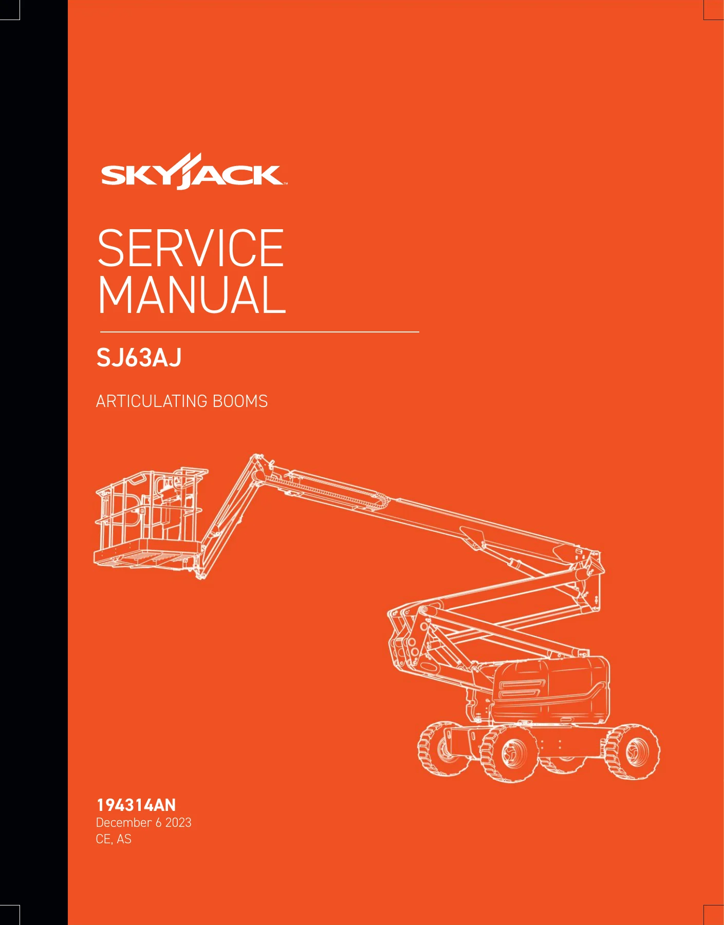
Skyjack SJ63AJ Articulating Boom Lift Service Manual 194314AN 2023 — PDF page 1 preview
Skyjack SJ63AJ Articulating Boom Lift Service Manual 194314AN 2023 — PDF page 50 preview
Skyjack SJ63AJ Articulating Boom Lift Service Manual 194314AN 2023 — PDF page 91 preview

Boom, Turret and Axle Work

The boom procedures in Section 5.3 walk through the whole job: checking and shimming wear pads, replacing boom section wear pads, removing and installing the platform and jib as an assembly, fly boom removal and installation, extension cylinder removal and installation, main boom lift cylinder removal and installation, and riser cylinder removal and installation. Limit switch locations and replacement procedures are given for the main boom, riser boom and fly boom, along with how to test each switch. The turret section covers the high pressure filter, turret rotation gear backlash adjustment, swing drive motor removal, swing drive oil change, rotation bearing axial wear check, turret rotation gear bolt torque sequence, electronic tilt switch setup and reprogramming, and battery replacement. The axle section covers oil changes in the axles, torque hubs and axle gearbox, oscillating cylinder bolt replacement and full cylinder replacement, bleeding the oscillating axle cylinders, pin brake adjustments, and brake inspection with a 4.5 mm feeler gauge.

Hydraulic and Electrical Schematics

Section 3 contains the hydraulic schematic and the full set of electrical schematics organised by region (ANSI/CSA, CE, AS) and engine. There are base control box wiring diagrams, platform control box wiring diagrams, engine interface harness diagrams, glow plug harness diagrams, engine electrical schematics, and separate diagrams for options like the hydraulic generator, welder, oil cooler, load sensing, all motion alarm, and positive air shutoff. Hydraulic port identification diagrams cover the rotary manifold, brake manifold, drive and system pump, drive motor, jib valve, and main manifold. The wire number and colour code chart is included, which is essential when tracing a fault through a harness.

Why This Manual Matters

An articulating boom lift is a complex machine with interlocked safety systems, load sensing, tilt protection, and multiple engine options. Servicing it without the correct torque values, relief valve settings, or schematic for the exact serial range and engine variant is how components get damaged and machines get pulled from service. This Skyjack SJ63AJ service manual gives the technician the exact procedure, the exact specification, and the exact fault tree for the machine in front of them. The relief valve adjustment procedures alone — system relief, turret rotate, platform level, riser down, main boom down, fly boom, brake pressure, charge pump, forward and reverse drive, standby and high pressure — are the kind of information that is not available anywhere else in one place.

Instant PDF Delivery

The manual is delivered as an instant PDF download after payment. There is no shipping, no waiting for a disc, and no physical book to keep track of in the shop. You can open it on any device — laptop, tablet, or phone — and print the pages you need for the job at hand. Whether you are doing a scheduled annual inspection, chasing an electrical fault on a Deutz TD2.9L machine, or rebuilding a boom cylinder, the relevant section is a click away. Keep a copy on the shop computer and another on a tablet in the service truck, and you have the full Skyjack SJ63AJ service reference wherever the machine is.
Reviews

There are no reviews yet.

Be the first to review “Skyjack SJ63AJ Articulating Boom Lift Service Manual 194314AN 2023”

What Our Customers Say

★★★★★ Live reviews from customers
Loading customer reviews...
0
    0
    Your Cart
    Your cart is emptyReturn to Shop
    🛒
    Recently Purchased
    🕒 verified order