Description
Bobcat S570 Skid-Steer Loader Service Manual 6990681enUS February 2019 PDF
This Bobcat S570 Skid-Steer Loader Service Manual 6990681enUS February 2019 PDF is the shop-level service document written for mechanics working on the S570 skid-steer loader. Publication 6990681enUS (02-19) (K) applies to machines with loader serial numbers ALM411001 and above and B3GZ11001 and above. The February 2019 English edition runs 1290 pages and gathers lifting and blocking practice, scheduled maintenance, hydraulic and hydrostatic repair, chaincase and brake work, cab and frame service, electrical diagnosis, engine overhaul steps, HVAC procedures, and the full specification set for this model.
File Details
- Manual type: Service Manual
- Brand / model: Bobcat S570 Skid-Steer Loader
- Language: English (enUS)
- Page count: 1290
- File format: PDF
- Document number: 6990681enUS (02-19) (K)
- Date: February 2019
- Serial coverage: S/N ALM411001 & Above; S/N B3GZ11001 & Above
Which Machines This Manual Fits
Use the serial plate on the outside of the loader frame before ordering parts or starting a procedure. Earlier or later S570 units can use different components, and this 6990681enUS book is written around the ALM411001 and B3GZ11001 ranges printed on the cover. The engine serial number sits on the side of the engine next to the oil fill cap. Inside the engine chapter the S570 is identified with a Bobcat direct-injected D24NAP turbocharged and intercooled diesel, 2.4 L class, four cylinders, closed breather, and counterclockwise rotation viewed from the flywheel. The specification tables list the powerplant as Bobcat Engine / 2.4L Bobcat Engine Tier 4.
Control layouts covered in the same book include standard steering levers and foot pedals, optional Advanced Control System (ACS), and optional Selectable Joystick Controls (SJC). High-flow hydraulics, two-speed travel, Power Bob-Tach, deluxe instrumentation, keyless start, and HVAC equipment receive their own removal, test, and calibration steps when the machine is so equipped.
Complete PDF Bookmark Tree
Complete Bookmarks
The complete bookmarks in the “Bobcat S570 Skid-Steer Loader Service Manual 6990681enUS February 2019 PDF” are as follows:
MAINTENANCE SAFETYp. 3
CONTENTSp. 5
+FOREWORDp. 7
FOREWORDp. 9
SAFETY INSTRUCTIONSp. 11
+FIRE PREVENTIONp. 13
Maintenancep. 13
Operationp. 13
Electricalp. 13
Hydraulic Systemp. 13
Fuelingp. 13
Startingp. 13
Spark Arrester Exhaust Systemp. 13
Welding And Grindingp. 14
Fire Extinguishersp. 14
+SERIAL NUMBER LOCATIONSp. 15
Loader Serial Numberp. 15
Engine Serial Numberp. 15
DELIVERY REPORTp. 16
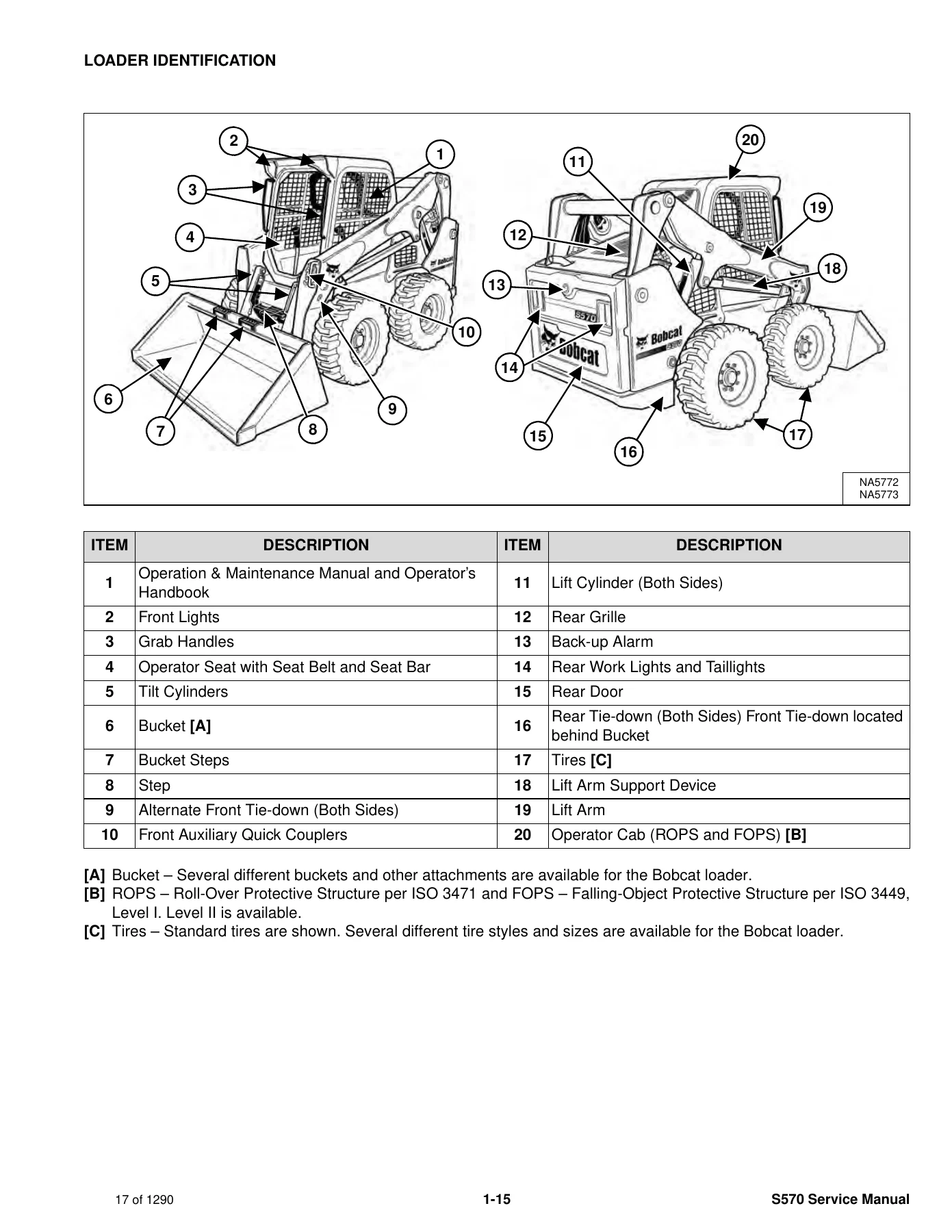
LOADER IDENTIFICATIONp. 17
+SAFETY AND MAINTENANCEp. 19
+LIFTING AND BLOCKING THE LOADERp. 23
+LIFT ARM SUPPORT DEVICEp. 25
Descriptionp. 25
Installingp. 26
Removingp. 27
+OPERATOR CABp. 29
Descriptionp. 29
Cab Door Sensorp. 29
Raisingp. 30
Loweringp. 31
Special Applications Kitp. 32
Special Applications Kit Inspection And Maintenancep. 32
Forestry Door And Window Kitp. 33
Forestry Door And Window Kit Inspection And Maintenancep. 33
+TRANSPORTING THE LOADER ON A TRAILERp. 35
Loading And Unloadingp. 35
Fasteningp. 35
+TOWING THE LOADERp. 37
+REMOTE START TOOL KIT – MEL1563p. 39
Remote Start Tool – MEL1563p. 39
Service Tool Harness Communicator – MEL1566p. 40
Remote Start Procedurep. 41
+REMOTE START TOOL (SERVICE TOOL) KIT – 7217666p. 45
Descriptionp. 45
Remote Start Tool (Service Tool) – 7022042p. 46
Loader Service Tool Harness – 6689747p. 47
Computer Service Tool Harness – 6689746p. 48
Remote Start Procedurep. 49
+SERVICE SCHEDULEp. 53
Maintenance Intervalsp. 53
+ENGINE AIR CLEANERp. 55
+ENGINE COOLING SYSTEMp. 57
Maintenance Platformp. 57
Cleaningp. 57
Checking And Adding Coolantp. 60
Removing And Replacing Coolantp. 61
+FUEL SYSTEMp. 63
Fuel Specificationsp. 63
Biodiesel Blend Fuelp. 63
Filling The Fuel Tankp. 64
Fuel Filterp. 65
Removing Air From The Fuel Systemp. 67
+ENGINE LUBRICATION SYSTEMp. 69
Checking And Adding Engine Oilp. 69
Engine Oil Chartp. 69
Removing And Replacing Oil And Filterp. 70
+HYDRAULIC / HYDROSTATIC SYSTEMp. 73
Checking And Adding Fluidp. 73
Hydraulic / Hydrostatic Fluid Chartp. 73
Removing And Replacing Hydraulic Fluidp. 74
Removing And Replacing Hydraulic / Hydrostatic Filterp. 76
Removing And Replacing Hydraulic Charge Filterp. 77
Replacing Reservoir Breather Capp. 79
+FINAL DRIVE TRANSMISSION (CHAINCASE)p. 81
Checking And Adding Fluidp. 81
Removing And Replacing Fluidp. 81
+BOB-TACH (HAND LEVER)p. 83
Inspection And Maintenancep. 83
+BOB-TACH (POWER)p. 85
Inspection And Maintenancep. 85
+LUBRICATING THE LOADERp. 87
Lubrication Locationsp. 87
+TIRE MAINTENANCEp. 91
Wheel Nutsp. 91
Rotatingp. 91
Mountingp. 92
+PIVOT PINSp. 93
Inspection And Maintenancep. 93
+LOADER STORAGE AND RETURN TO SERVICEp. 95
Storagep. 95
Return To Servicep. 95
+STOPPING THE ENGINE AND LEAVING THE LOADERp. 97
+EMERGENCY EXITp. 99
Rear Window Identificationp. 99
Rear Window Removal (Latches)p. 99
Rear Window Removal (Rubber Cord)p. 99
External Access (Rear Window With Latches)p. 100
External Access (Rear Window With Rubber Cord)p. 100
Front Doorp. 100
+SEAT BELTp. 103
Inspection And Maintenancep. 103
+HYDRAULIC SYSTEMp. 105
HYDRAULIC / HYDROSTATIC SCHEMATICSp. 111
+HYDRAULIC SYSTEM INFORMATIONp. 127
Glossary Of Hydraulic / Hydrostatic Symbolsp. 127
Troubleshootingp. 131
+CYLINDER (LIFT)p. 133
Testingp. 133
Removal And Installationp. 134
Parts Identificationp. 137
Disassemblyp. 138
Assemblyp. 140
+CYLINDER (TILT)p. 143
Testingp. 143
Removal And Installationp. 144
Base End Pivot Pin Removal And Installationp. 145
Parts Identificationp. 146
Disassemblyp. 147
Assemblyp. 149
+CYLINDER (LIFT) (B3GZ11341 & ABOVE)p. 153
Testingp. 153
Removal And Installationp. 154
Parts Identificationp. 158
Disassemblyp. 159
Assemblyp. 161
+CYLINDER (TILT) (B3GZ11341 & ABOVE)p. 165
Testingp. 165
Removal And Installationp. 166
Base End Pivot Pin Removal And Installationp. 167
Parts Identificationp. 168
Disassemblyp. 169
Assemblyp. 171
+CYLINDER (BOB-TACH)p. 175
Testingp. 175
Removal And Installationp. 176
Parts Identificationp. 177
Disassemblyp. 178
Assemblyp. 179
+MAIN RELIEF VALVEp. 183
Descriptionp. 183
Testingp. 184
Adjustingp. 186
Removal And Installationp. 187
+HYDRAULIC CONTROL VALVE (STANDARD)p. 189
Descriptionp. 189
Removal And Installationp. 190
Mount Bracket Removal And Installationp. 193
Identification Chartp. 194
Lift Load Check Valve Removal And Installationp. 195
Load Check Valve Removal And Installation (Tilt And Auxiliary)p. 196
Anti-Cavitation Valve Removal And Installation (Lift, Rod End)p. 197
Port Relief / Anti-Cavitation Valve Removal And Installation (Lift, Base End)p. 197
Port Relief / Anti-Cavitation Valve Removal And Installation (Tilt, Base End)p. 198
Port Relief / Anti-Cavitation Valve Removal And Installation (Tilt, Rod End)p. 198
Port Relief Valve Removal And Installationp. 199
Plug Removal And Installationp. 201
Rubber Boot Removal And Installationp. 202
End Cap Block Removal And Installationp. 202
Lift Spool And Detent Removal And Installationp. 203
Tilt Spool Removal And Installationp. 211
Auxiliary Spool Removal And Installationp. 213
Auxiliary Solenoid Removal And Installationp. 214
Solenoid Removal And Installationp. 215
Lock Valve Removal And Installationp. 216
Lift Arm Bypass Orifice Removal And Installationp. 218
Main Relief Valve Removal And Installationp. 218
Check Valve Removal And Installationp. 219
+HYDRAULIC CONTROL VALVE (ACS) OR (SJC)p. 221
Descriptionp. 221
Removal And Installationp. 221
Actuator Removal And Installation (In Loader)p. 226
Actuator Removal And Installation (Out Of Loader)p. 228
Identification Chartp. 231
Mount Bracket Removal And Installationp. 232
Lift Load Check Valve Removal And Installationp. 232
Load Check Valve Removal And Installation (Tilt And Auxiliary)p. 233
Anti-Cavitation Valve Removal And Installation (Lift, Rod End)p. 234
Port Relief / Anti-Cavitation Valve Removal And Installation (Lift, Base End)p. 234
Port Relief / Anti-Cavitation Valve Removal And Installation (Tilt, Base End)p. 235
Port Relief / Anti-Cavitation Valve Removal And Installation (Tilt, Rod End)p. 235
Port Relief Valve Removal And Installationp. 236
Plug Removal And Installationp. 238
End Cap Block Removal And Installationp. 239
Lift Spool Removal And Installationp. 239
Lift Spool Disassembly And Assemblyp. 241
Tilt Spool Removal And Installationp. 242
Auxiliary Spool Removal And Installationp. 244
Auxiliary Solenoid Removal And Installationp. 245
Solenoid Removal And Installationp. 246
Lock Valve Removal And Installationp. 247
Lift Arm Bypass Orifice Removal And Installationp. 249
Main Relief Valve Removal And Installationp. 249
Check Valve Removal And Installationp. 250
+LIFT ARM BYPASS CONTROL VALVEp. 251
Descriptionp. 251
Testingp. 251
Removal And Installationp. 252
Bracket Removal And Installationp. 253
Disassembly And Assemblyp. 253
+HYDRAULIC PUMPp. 255
Descriptionp. 255
Pump Test At Quick Couplersp. 256
Direct Pump Test (Standard Section)p. 258
Direct Pump Test (Charge Section)p. 260
Removal And Installationp. 262
Hydraulic Pump Startupp. 264
Parts Identificationp. 265
Disassembly And Assemblyp. 266
+HYDRAULIC PUMP (HIGH FLOW)p. 267
Descriptionp. 267
Pump Test At Quick Couplersp. 268
Direct Pump Test (Standard Section)p. 270
Direct Pump Test (Charge Section)p. 271
Direct Pump Test (High Flow Section)p. 273
High Flow Relief Valve Adjustmentp. 275
High Flow Relief Valve Removal And Installationp. 277
Solenoid Removal And Installationp. 278
Removal And Installationp. 279
Hydraulic Pump Startupp. 281
Parts Identificationp. 282
Disassembly And Assemblyp. 283
+HYDRAULIC / HYDROSTATIC FILTERSp. 285
Descriptionp. 285
Housing Removal And Installationp. 285
+HYDRAULIC FLUID RESERVOIRp. 287
Descriptionp. 287
Removal And Installationp. 287
Hydraulic Fluid Screenp. 288
+OIL COOLERp. 289
Removal And Installationp. 289
+BUCKET POSITION VALVEp. 291
Descriptionp. 291
Solenoid Removal And Installationp. 291
Solenoid Testingp. 293
Removal And Installationp. 293
Disassembly And Assemblyp. 295
+REAR AUXILIARY DIVERTER VALVEp. 297
Descriptionp. 297
Solenoid Testingp. 297
Removal And Installationp. 298
Disassembly And Assemblyp. 299
+BOB-TACH (POWER) BLOCK (S/N ALM411001 – ALM413900)p. 305
Descriptionp. 305
Removal And Installationp. 305
Disassembly And Assemblyp. 307
+BOB-TACH (POWER) BLOCK (S/N ALM413901 AND B3GZ11001 & ABOVE)p. 315
Descriptionp. 315
Testing Relief Valvep. 316
Removal And Installationp. 317
Disassembly And Assemblyp. 319
+FRONT AUXILIARY HYDRAULIC COUPLER BLOCKp. 325
Descriptionp. 325
Removal And Installationp. 326
Disassembly And Assembly (FFI/FI)p. 326
Disassembly And Assembly (FFH/FH)p. 328
+AUTOMATIC RIDE CONTROLp. 331
Descriptionp. 331
Removal And Installationp. 332
Checking The Pressure In The Accumulatorp. 335
Adding Nitrogen To The Accumulatorp. 337
+HYDROSTATIC SYSTEMp. 339
+HYDROSTATIC SYSTEM INFORMATIONp. 341
Descriptionp. 341
Troubleshootingp. 342
+HYDROSTATIC DRIVE MOTORp. 343
Descriptionp. 343
Removal And Installationp. 343
Parts Identificationp. 346
Disassembly And Assemblyp. 347
+HYDROSTATIC DRIVE MOTOR (TWO-SPEED)p. 353
Descriptionp. 353
Removal And Installation (Left Side)p. 354
Removal And Installation (Right Side)p. 357
Parts Identificationp. 360
Disassemblyp. 361
Assemblyp. 374
+HYDROSTATIC MOTOR CARRIERp. 389
Descriptionp. 389
Shaft Seal Removal And Installationp. 390
Removal And Installationp. 392
Parts Identificationp. 394
Disassemblyp. 395
Assemblyp. 397
+HYDROSTATIC MOTOR CARRIER (TWO-SPEED)p. 401
Descriptionp. 401
Shaft Seal Removal And Installationp. 402
Removal And Installationp. 404
Parts Identificationp. 406
Disassemblyp. 407
Assemblyp. 409
+CHARGE PRESSUREp. 413
Descriptionp. 413
Testingp. 414
Adjustingp. 416
Sender Removal And Installation (Earlier Models)p. 418
Sender Removal And Installation (Later Models)p. 418
+HYDROSTATIC PUMPp. 419
Descriptionp. 419
Removal And Installationp. 420
Hydrostatic Pump Startupp. 421
Replenishing / High Pressure Relief Valve Removal And Installationp. 422
Parts Identification (Left Half)p. 423
Parts Identification (Right Half)p. 424
Disassemblyp. 425
Assemblyp. 432
+HYDROSTATIC PUMP (SJC)p. 439
Descriptionp. 439
Hydraulic Controller Removal And Installationp. 440
Removal And Installationp. 442
Hydrostatic Pump Startupp. 444
Parts Identificationp. 445
High Pressure Relief And Bypass Valvep. 446
Charge Relief Valvep. 447
Disassembly And Assemblyp. 448
Mechanical Neutral Adjustmentp. 461
Hydraulic Controller Neutral Adjustmentp. 464
+HYDROSTATIC PUMP (SJC) (S/N ALM425401 & ABOVE)p. 467
Descriptionp. 467
Port Locations And Gauge Installationp. 468
Removal And Installationp. 469
Hydrostatic Pump Startupp. 471
Parts Identificationp. 472
High Pressure Relief And Bypass Valvep. 475
Charge Pressure Relief Valvep. 476
Disassembly And Assemblyp. 477
Mechanical Neutral Adjustmentp. 489
Hydraulic Controller Neutral Adjustmentp. 491
+DRIVE BELTp. 493
Belt Adjustmentp. 493
Stop Adjustmentp. 493
Belt Replacementp. 494
Tensioner Pulley Removal And Installation (Earlier Models)p. 496
Tensioner Pulley Disassembly And Assemblyp. 496
Tensioner Pulley Removal And Installation (Later Models)p. 497
Tensioner Pulley Disassembly And Assemblyp. 497
+TWO-SPEEDp. 499
Valve Block Removal And Installationp. 499
Valve Block Disassembly And Assemblyp. 500
+DRAIN MANIFOLDp. 501
Descriptionp. 501
Drain Manifold Removal And Installationp. 501
+DRIVE SYSTEMp. 503
+BRAKEp. 505
Descriptionp. 505
Disc Removal And Installationp. 505
+DRIVE COMPONENTSp. 507
Descriptionp. 507
Axle Seal Removal And Installationp. 508
Axle, Sprocket And Bearings Removal And Installationp. 510
Chain Removal And Installationp. 515
+CHAINCASEp. 517
Descriptionp. 517
Front Cover Removal And Installationp. 517
Center Cover Removal And Installationp. 518
Rear Cover Removal And Installationp. 519
+MAINFRAMEp. 521
+SEAT BARp. 525
Descriptionp. 525
Removal And Installationp. 525
Disassembly And Assemblyp. 526
Compression Spring Disassembly And Assemblyp. 527
+OPERATOR CABp. 529
Gas Spring Removal And Installationp. 529
Gas Spring Bracket Disassembly And Assemblyp. 530
Removal And Installationp. 530
+OPERATOR SEATp. 533
Removal And Installationp. 533
Seat Belt Removal And Installation (Retractable)p. 533
Seat Belt And Bracket Removal And Installation (Standard)p. 534
Seat Belt Bracket Removal And Installationp. 534
+OPERATOR SEAT (SUSPENSION)p. 535
Removal And Installationp. 535
Slide Rail Removal And Installationp. 535
Seat Belt Removal And Installationp. 536
Lower Cushion Removalp. 536
Lower Cushion Installationp. 537
Back Cushion Removal And Installationp. 537
Shock Removal And Installationp. 538
3-Point Seat Belt Removal And Installationp. 538
+BOB-TACH (HAND LEVER)p. 541
Descriptionp. 541
Removal And Installationp. 541
Lever And Wedge Disassembly And Assemblyp. 544
Pivot Pin Bushing And Seal Removal And Installationp. 546
+BOB-TACH (POWER)p. 547
Descriptionp. 547
Removal And Installationp. 547
Lever And Wedge Disassembly And Assemblyp. 550
Pivot Pin Bushing And Seal Removal And Installationp. 552
+LIFT ARMSp. 553
Stabilizer Bar Removal And Installationp. 553
Link Removal And Installationp. 554
Removal And Installationp. 555
+REAR GRILLEp. 559
Removingp. 559
Installingp. 559
Shield Removal And Installationp. 560
+REAR DOOR (TAILGATE)p. 561
Removal And Installationp. 561
Striker Removal And Installationp. 562
Striker Disassembly And Assemblyp. 562
Striker Adjustingp. 563
Latch Removal And Installationp. 564
+FUEL TANKp. 565
Removal And Installationp. 565
Fuel Level Sender Removal And Installationp. 567
Fuel Fill Screen Removal And Installationp. 567
+CONTROL PEDALS AND LINKAGESp. 569
Descriptionp. 569
Pedal Removal And Installationp. 569
Linkage Removal And Installationp. 570
Pedal (Adjusting)p. 571
Floor Pan Removal And Installationp. 572
+CONTROL PEDALS AND LINKAGES (ACS)p. 573
Descriptionp. 573
Pedal Removal And Installationp. 573
Linkage Removal And Installationp. 574
Pedal (Adjusting)p. 574
Floor Pan Removal And Installationp. 575
+CONTROL PANELp. 577
Descriptionp. 577
Removal And Installationp. 578
Disassembly And Assemblyp. 579
Linkage Removal And Installationp. 583
Pintle Arm Disassembly And Assemblyp. 587
Linkage Neutral (Adjusting)p. 588
Linkage Travel (Adjusting)p. 592
Shock Removal And Installationp. 596
+CONTROL PANEL (SJC)p. 597
Descriptionp. 597
Removal And Installationp. 597
+CONTROL HANDLE / LEVERp. 599
Descriptionp. 599
Lever Removal And Installationp. 599
Boot Removal And Installationp. 600
+CONTROL HANDLE / LEVER (ACS)p. 601
Descriptionp. 601
Handle Sensor Removal And Installationp. 601
Handle Removal And Installationp. 604
Handle Disassembly And Assemblyp. 605
Lever Removal And Installationp. 605
Boot Removal And Installationp. 606
+CONTROL HANDLE / LEVER (SJC)p. 607
Descriptionp. 607
Joystick Testingp. 607
Joystick Removal And Installationp. 608
+ACCESS PANEL (INSIDE)p. 609
Removal And Installation (Left)p. 609
Removal And Installation (Right)p. 609
+ACCESS PANEL (INSIDE) (SJC)p. 611
Removal And Installation (Left)p. 611
Removal And Installation (Right)p. 611
+WINDOW (REAR)p. 613
Rear Window Identificationp. 613
Rear Window Removal (Latches)p. 613
Rear Window Removal (Rubber Cord)p. 613
External Access (Rear Window With Latches)p. 614
External Access (Rear Window With Rubber Cord)p. 614
Disassembly And Assembly (Latches)p. 615
+WINDOW (TOP)p. 617
Removal And Installationp. 617
+WINDOW (SIDE)p. 619
Removal And Installationp. 619
+CAB DOORp. 621
Descriptionp. 621
Removal And Installationp. 621
Disassembly And Assemblyp. 622
Aligningp. 623
Adjustingp. 624
Checking Operationp. 624
+ARMRESTp. 625
Descriptionp. 625
Removal And Installationp. 626
Disassembly And Assemblyp. 627
+LEFT SIDE LOWER PANELp. 629
Removal And Installationp. 629
Disassembly And Assemblyp. 632
+RIGHT SIDE LOWER PANELp. 633
Removal And Installationp. 633
Disassembly And Assemblyp. 635
+HEADLINERp. 637
Removal And Installationp. 637
+FAN DUCT PANELSp. 639
Removal And Installationp. 639
+ELECTRICAL SYSTEMp. 641
ELECTRICAL SCHEMATICSp. 647
+ELECTRICAL SYSTEM INFORMATIONp. 853
Glossary Of Electrical Symbolsp. 853
Standard Cab Harness Connectorsp. 856
Deluxe Cab Harness Connectorsp. 857
Mainframe Harness Connectors – Manual Controlsp. 858
Mainframe Harness Connectors – SJCp. 859
Engine Harness Connectorsp. 860
Descriptionp. 861
Troubleshootingp. 862
Fuse And Relay Location / Identificationp. 863
Solenoid Testingp. 868
+BATTERYp. 869
Removal And Installationp. 869
Battery Maintenancep. 870
Maintaining Battery Charge Levelp. 870
Battery Service During Machine Storagep. 870
Battery Testingp. 871
Battery Chargingp. 871
Using A Booster Battery (Jump Starting)p. 872
+ALTERNATORp. 873
Belt Adjustmentp. 873
Belt Replacementp. 874
Charging System Inspectionp. 875
Alternator Voltage Testingp. 876
Low Voltage Testingp. 876
High Voltage Testingp. 877
Removal And Installationp. 878
Parts Identificationp. 880
+STARTERp. 881
Testingp. 881
Removal And Installationp. 881
Parts Identificationp. 882
+INSTRUMENT PANELSp. 883
Left Panelp. 883
Display Screenp. 885
Right Panel (Standard Key Panel)p. 886
Right Panel (Keyless Start Panel)p. 887
Right Panel (Deluxe Instrumentation Panel)p. 888
Left Switch Panelp. 890
Right Switch Panelp. 890
Left Side Lower Panelp. 891
Right Side Lower Panelp. 891
Left Panel Removal And Installationp. 892
Right Panel (Standard Key Panel) Removal And Installationp. 892
Right Panel (Keyless Start Panel) Removal And Installationp. 893
Right Panel (Deluxe Instrumentation Panel) Removal And Installationp. 893
Key Switch Disassembly And Assemblyp. 894
Alarm Disassembly And Assemblyp. 894
Left Switch Panel Removal And Installationp. 895
Right Switch Panel Removal And Installationp. 895
+LIGHTSp. 897
Front Removal And Installationp. 897
Rear Removal And Installationp. 898
Cab Light Removal And Installation (Earlier Models)p. 898
Cab Light Removal And Installation (Later Models)p. 899
+BOBCAT CONTROLLERS (GATEWAY AND AUXILIARY)p. 901
Descriptionp. 901
Connector Identificationp. 902
Removal And Installationp. 908
+BOBCAT CONTROLLER (ACS)p. 909
Descriptionp. 909
Connector And Wire Identificationp. 910
Removal And Installationp. 911
+BOBCAT CONTROLLER (SJC) (DRIVE)p. 913
Descriptionp. 913
Connector Identificationp. 914
Removal And Installationp. 916
+ENGINE CONTROL UNIT (ECU)p. 917
Descriptionp. 917
Cleaningp. 918
Removal And Installationp. 919
+DIAGNOSTIC SERVICE CODESp. 921
Viewing Service Codesp. 921
Service Codes Listp. 922
+BOBCAT INTERLOCK CONTROL SYSTEM (BICS™)p. 931
Descriptionp. 931
Inspecting The BICS™ (Engine STOPPED – Key ON)p. 932
Inspecting Deactivation Of The Auxiliary Hydraulics System (Engine STOPPED – Key ON)p. 932
Inspecting The Seat Bar Sensor (Engine RUNNING)p. 932
Inspecting The Traction Lock And Parking Brake (Engine RUNNING)p. 932
Inspecting The Lift Arm Bypass Controlp. 932
Inspecting Deactivation Of Lift And Tilt Functions (ACS And SJC)p. 932
Troubleshootingp. 933
+SEAT BAR SENSORp. 935
Descriptionp. 935
Troubleshootingp. 935
Testingp. 936
Removalp. 937
Installationp. 939
Bobcat Interlock Control System (BICS™) Circuit Testp. 940
+TRACTION LOCKp. 943
Descriptionp. 943
Troubleshootingp. 944
Inspectingp. 945
+CONTROL SYSTEM (ACS)p. 947
Descriptionp. 947
Troubleshootingp. 948
Handle Sensor Connector Disassembly And Assemblyp. 949
Switch Handle Removalp. 950
Switch Handle Installationp. 952
Actuator Connector Disassembly And Assemblyp. 955
Handle Lock Solenoid Removal And Installationp. 956
Handle Lock Solenoid Disassembly And Assemblyp. 956
Foot Sensor Removal And Installationp. 957
Foot Sensor Disassembly And Assemblyp. 958
Foot Sensor Lock Solenoid Removal And Installationp. 958
+ELECTRICAL / HYDRAULIC CONTROLSp. 959
Identification Chartp. 959
Descriptionp. 960
Identification Chart ACD Group 0p. 961
Identification Chart ACD Group 1p. 962
Identification Chart ACD Group 2p. 963
Identification Chart ACD Group 3p. 964
+ELECTRICAL / HYDRAULIC CONTROLS (ACS)p. 965
Identification Chartp. 965
Descriptionp. 966
Identification Chart ACD Group 0p. 967
Identification Chart ACD Group 1p. 968
Identification Chart ACD Group 2p. 969
Identification Chart ACD Group 3p. 970
+ELECTRICAL / HYDRAULIC CONTROLS (SJC)p. 971
Identification Chartp. 971
Descriptionp. 972
Identification Chart ACD Group 0p. 973
Identification Chart ACD Group 1p. 974
Identification Chart ACD Group 2p. 975
Identification Chart ACD Group 3p. 976
+SERVICE PC (LAPTOP COMPUTER)p. 977
Connecting Remote Start Toolp. 977
Connecting Remote Start Tool (Service Tool)p. 977
+CALIBRATIONp. 979
Descriptionp. 979
Actuator Testingp. 979
Lift And Tilt Calibration (SJC)p. 982
Hydrostatic Pump Calibration (SJC)p. 984
Lift And Tilt Calibration (ACS)p. 989
+STEERING DRIFT COMPENSATION (OPERATOR MODE)p. 991
Descriptionp. 991
Operationp. 991
+STEERING DRIFT COMPENSATION (SERVICE MODE)p. 993
Descriptionp. 993
Operationp. 993
+CONTROL PANEL SETUPp. 995
Right Panel Setup (Deluxe Instrumentation Panel)p. 995
+PASSWORD SETUP (DELUXE INSTRUMENTATION PANEL)p. 999
Password Descriptionp. 999
Changing The Owner Passwordp. 999
Changing The User Passwordsp. 1000
Password Lockout Featurep. 1000
+PASSWORD SETUP (KEYLESS START PANEL)p. 1001
Password Descriptionp. 1001
Changing The Owner Passwordp. 1001
Password Lockout Featurep. 1001
+MAINTENANCE CLOCKp. 1003
Descriptionp. 1003
Setupp. 1004
Resetp. 1007
+BACK-UP ALARM SYSTEMp. 1009
Descriptionp. 1009
Inspectingp. 1009
Adjusting Switch Positionp. 1010
Troubleshooting (Standard And ACS)p. 1011
Troubleshooting (Joystick)p. 1012
Alarm Removal And Installationp. 1013
Switch Removal And Installationp. 1013
+FRONT HORNp. 1015
Removal And Installationp. 1015
Troubleshootingp. 1016
Troubleshooting (Joystick)p. 1017
+ENGINE SPEED CONTROL (HAND)p. 1019
Removal And Installationp. 1019
+ENGINE SPEED CONTROL (FOOT)p. 1021
Removal And Installationp. 1021
Disassembly And Assemblyp. 1022
Foot Throttle Calibrationp. 1024
+CAMSHAFT AND CRANKSHAFT POSITION SENSORp. 1027
Removal And Installationp. 1027
+TELEMATICSp. 1029
Descriptionp. 1029
Removal And Installationp. 1029
Procedurep. 1030
+ENGINE SERVICEp. 1031
+ENGINE INFORMATIONp. 1035
Descriptionp. 1035
Specificationsp. 1036
Sensor Locationp. 1038
Torque Valuesp. 1044
Troubleshootingp. 1046
Engine Removal And Installationp. 1048
Engine Mount Replacementp. 1057
Compression – Testingp. 1059
Injector Signal – Testingp. 1061
Injector Signal – Testing (In-Line)p. 1063
Oil Pressure Testing (At Oil Sensor On Block)p. 1065
Oil Pressure Testing (At Turbocharger Oil Inlet)p. 1067
+DIESEL OXIDATION CATALYST (DOC)p. 1069
Removal And Installationp. 1069
+AIR CLEANERp. 1071
Housing Removal And Installationp. 1071
+ENGINE COOLING SYSTEM (EARLIER MODELS)p. 1073
Radiator / Oil Cooler Removal And Installationp. 1073
Hydraulic Fan Descriptionp. 1076
Fan Duct Removal And Installationp. 1076
Hydraulic Fan Motor Assembly Removal And Installationp. 1077
Hydraulic Fan Motor Removal And Installationp. 1078
Hydraulic Fan Motor Disassembly And Assemblyp. 1080
Blower Housing Removal And Installationp. 1081
Water Pump Removal And Installationp. 1082
Thermostat Housing Removal And Installationp. 1083
Testing The Thermostatp. 1084
+ENGINE COOLING SYSTEM (LATER MODELS)p. 1085
Radiator / Oil Cooler Removal And Installationp. 1085
Hydraulic Fan Descriptionp. 1088
Reversible Hydraulic Fan Descriptionp. 1088
Fan Duct Removal And Installationp. 1088
Hydraulic Fan Motor Assembly Removal And Installationp. 1089
Hydraulic Fan Motor Removal And Installationp. 1090
Hydraulic Fan Motor Disassembly And Assemblyp. 1092
Hydraulic Fan Motor Assembly Removal And Installationp. 1100
Hydraulic Fan Motor Removal And Installationp. 1101
Hydraulic Fan Motor Disassembly And Assemblyp. 1103
Blower Housing Removal And Installationp. 1108
Water Pump Removal And Installationp. 1109
Thermostat Housing Removal And Installationp. 1110
Testing The Thermostatp. 1111
+LUBRICATION SYSTEMp. 1113
Descriptionp. 1113
Oil Pan Removal And Installationp. 1114
Oil Pump Removal And Installationp. 1115
Oil Pump Relief Valve Descriptionp. 1116
Oil Pump Relief Valve Removal And Installationp. 1116
Oil Cooler Removal And Installationp. 1117
Oil Filter Head Removal And Installationp. 1118
Oil Cooler Bypass Descriptionp. 1119
Oil Cooler Bypass Removal And Installationp. 1119
+FUEL SYSTEMp. 1121
Descriptionp. 1121
Transfer Pump / High Pressure Pump Removal And Installationp. 1122
Fuel Temperature Sensor Removal And Installationp. 1124
Fuel Cooler Removal And Installationp. 1125
Fuel Bypass Valve Removal And Installationp. 1125
Fuel Recirculation Valve Removal And Installationp. 1126
Fuel Rail Assembly Removal And Installationp. 1127
Fuel Injector Removal And Installationp. 1128
Injector Codingp. 1130
Removing Air From The Fuel Systemp. 1132
+CYLINDER HEADp. 1135
Glow Plugs Testingp. 1135
Glow Plug Removal And Installationp. 1136
Valve Clearance Adjustmentp. 1137
Cylinder Head Removal And Installationp. 1139
Cylinder Head Disassembly And Assemblyp. 1143
Cylinder Head Inspectionp. 1144
Cylinder Head Top Clearancep. 1145
Valve Step Heightp. 1146
Valve Stem Heightp. 1146
Valve Guidep. 1147
Valvep. 1147
Valve Springp. 1148
Rocker Arm Shaft Disassembly And Assemblyp. 1149
Rocker Arm Shaft Inspectionp. 1150
Push Rod Inspectionp. 1150
+CRANKSHAFT AND PISTONSp. 1151
Piston And Connecting Rod Removal And Installationp. 1151
Piston And Connecting Rod Inspectionp. 1152
Crankshaft Removal And Installationp. 1154
Cylinder Block Inspectionp. 1157
Crankshaft Inspectionp. 1159
Connecting Rod Inspectionp. 1159
Engine Component Classp. 1160
+CAMSHAFTp. 1163
Removal And Installationp. 1163
Inspectingp. 1164
+GEARCASEp. 1167
Gearcase Cover Removal And Installationp. 1167
Gear Backlashp. 1168
Gear Timingp. 1169
Idle Gear Removal And Installationp. 1170
Idle Gear Inspectionp. 1170
+TURBOCHARGERp. 1171
Descriptionp. 1171
Removal And Installationp. 1171
Inspectionp. 1174
+FLYWHEEL AND HOUSINGp. 1175
Flywheel Removal And Installationp. 1175
Ring Gear Removal And Installationp. 1176
Housing Removal And Installationp. 1176
+EXHAUST GAS RECIRCULATION (EGR) SYSTEMp. 1177
Descriptionp. 1177
Removal And Installationp. 1178
Disassembly And Assemblyp. 1182
+HEATING, VENTILATION AND AIR CONDITIONING (HVAC)p. 1185
+AIR CONDITIONING SYSTEM FLOWp. 1187
Descriptionp. 1187
Chartp. 1188
Componentsp. 1189
Safety Equipmentp. 1192
+REGULAR MAINTENANCEp. 1193
Filtersp. 1193
Belt Adjustmentp. 1194
Belt Replacementp. 1194
Air Conditioning Condenserp. 1194
Air Conditioning Lubricationp. 1194
Air Conditioning Service Chartp. 1195
Evaporator / Heater Coilp. 1196
+TROUBLESHOOTINGp. 1199
Blower Motor Does Not Operatep. 1199
Blower Motor Operates Normally, But Air Flow Is Insufficientp. 1199
Insufficient Cooling Although Air Flow And Compressor Operation Are Normalp. 1199
The Compressor Does Not Operate At All, Or Operates Improperlyp. 1199
Gauge Pressure Related Troubleshootingp. 1200
Troubleshooting Treep. 1202
Temperature / Pressure Chartp. 1206
Poor A/C Performancep. 1208
HVAC Repair And Leaksp. 1209
Electrical Systemp. 1210
Engine Coolant Bypassing The Heater Valvep. 1216
Heater Valve Not Opening Or Closingp. 1217
+SYSTEM CHARGING AND RECLAMATIONp. 1219
Refrigerant Identificationp. 1219
Reclamation And Charging With Recovery / Charging Unitp. 1220
+COMPRESSORp. 1223
Removal And Installationp. 1223
Oilp. 1225
Oil Checkp. 1226
+CONDENSERp. 1229
Removal And Installationp. 1229
+RECEIVER / DRIERp. 1231
Receiver / Drier Removal And Installationp. 1231
Pressure Switch Removal And Installationp. 1233
Schrader® Valve Removal And Installationp. 1234
+EVAPORATOR / HEATER UNITp. 1235
Removal And Installationp. 1235
+THERMOSTATp. 1237
Descriptionp. 1237
Removal And Installationp. 1238
+EXPANSION VALVEp. 1239
Removal And Installationp. 1239
+EVAPORATOR COILp. 1241
Removal And Installationp. 1241
+HEATER COILp. 1243
Removal And Installationp. 1243
+BLOWER FANp. 1245
Removal And Installationp. 1245
Disassembly And Assemblyp. 1245
+HEATER VALVEp. 1249
Removal And Installationp. 1249
+EVAPORATOR / HEATER COVERp. 1251
Removingp. 1251
Installingp. 1251
+SPECIFICATIONSp. 1253
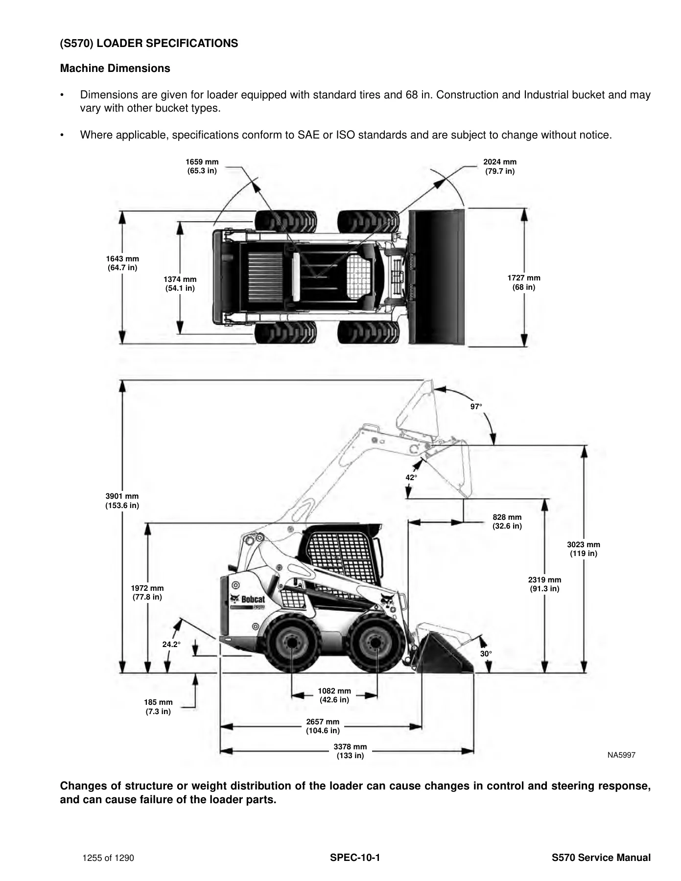
+(S570) LOADER SPECIFICATIONSp. 1255
Machine Dimensionsp. 1255
Performancep. 1256
Enginep. 1256
Drive Systemp. 1257
Controlsp. 1257
Hydraulic Systemp. 1258
Electrical Systemp. 1259
Capacitiesp. 1259
Tiresp. 1260
+TECHINCAL SERVICE GUIDE SPECIFICATIONSp. 1261
Enginep. 1261
Engine Torquesp. 1261
Cooling Systemp. 1261
Loader Torquesp. 1262
Hydraulic / Hydrostatic Systemp. 1262
Fuel Consumptionp. 1262
+TORQUE SPECIFICATIONS FOR BOLTSp. 1263
Torque For General SAE Boltsp. 1263
Torque For General Metric Boltsp. 1264
+HYDRAULIC CONNECTION SPECIFICATIONSp. 1265
Straight Thread O-ring Fittingp. 1265
Flare Fittingp. 1266
Tubelines And Hosesp. 1266
+HYDRAULIC / HYDROSTATIC FLUID SPECIFICATIONSp. 1267
+CONVERSIONSp. 1269
Decimal And Millimeter Equivalent Chartp. 1269
U.S. To Metric Conversion Chartp. 1269
+SERVICE TOOLS REQUIREDp. 1271
Remote Start Toolsp. 1271
Hydraulic Toolsp. 1272
Mainframe And Drive Toolsp. 1275
Electrical Toolsp. 1278
Engine Toolsp. 1279
HVAC Toolsp. 1284
ALPHABETICAL INDEXp. 1285
Chapters Covered
- Safety and Maintenance — lifting and blocking; lift arm support device; operator cab raise/lower; trailer transport and towing; remote start tools MEL1563 and 7217666; service schedule; air cleaner; cooling system; fuel system; engine lubrication; hydraulic/hydrostatic fluid and filters; chaincase fluid; Bob-Tach inspection; lubrication points; tires; pivot pins; storage; emergency exit; seat belt
- Hydraulic System — symbol glossary and troubleshooting; lift, tilt, and Bob-Tach cylinders (including B3GZ11341 & above); main relief valve; standard control valve; ACS/SJC control valve; lift arm bypass; standard and high-flow pumps; filters and reservoir; oil cooler; bucket position valve; rear auxiliary diverter; Power Bob-Tach blocks by serial break; front auxiliary coupler block; automatic ride control
- Hydrostatic System — drive motors (standard and two-speed); motor carriers; charge pressure test and adjustment; hydrostatic pump; SJC pump and ALM425401 & above pump; drive belt and tensioner; two-speed valve; drain manifold
- Drive System — parking brake discs; axle seals, sprockets, bearings, and chains; chaincase covers
- Mainframe — seat bar; operator cab and seats; hand-lever and Power Bob-Tach; lift arms; rear grille; fuel tank; control pedals and linkage; fan duct panels and related frame components
- Electrical System — harness connectors and fuses; battery, alternator, starter; instrument panels; lights; Gateway, Auxiliary, ACS, and SJC Drive controllers; ECU; diagnostic service codes; BICS™; seat bar sensor and traction lock; ACS control system; ACD groups 0–3; calibration; steering drift compensation; passwords and maintenance clock; back-up alarm; horn; hand and foot engine speed controls; camshaft/crankshaft sensors; telematics
- Engine Service — D24NAP information, specs, sensors, torques, troubleshooting; engine R&I and mounts; compression and injector signal tests; oil pressure tests; DOC; air cleaner housing; earlier and later cooling systems and hydraulic fan; lubrication and fuel systems; cylinder head and valves; crankshaft and pistons; turbocharger; flywheel; EGR
- Heating, Ventilation and Air Conditioning (HVAC) — system service, charging and reclamation, condenser, compressor, evaporator/heater unit, heater valve, covers
- Specifications — S570 loader dimensions, performance, engine, drive, controls, hydraulics, electrical, capacities, tires; technical service guide values; bolt and hydraulic connection torques; fluid viscosity chart; conversions; service tools
- Alphabetical Index
Taken together, the chapters give a technician a single path from daily checks and safe lift-arm support through component-level hydraulic, hydrostatic, engine, and electrical work. Serial-specific splits appear where hardware changed, including lift and tilt cylinders from B3GZ11341, Power Bob-Tach blocks at ALM413900/ALM413901, and the SJC hydrostatic pump from ALM425401.
Maintenance Intervals and Shop Safety
The service schedule in the opening section sets the rhythm for owning an S570. Before each shift the book calls for engine oil level, air-filter display codes, cooling-system cleaning, fuel-filter water drain, hydraulic fluid level, and a walk-around for leaks and damaged treads or signs. First-50-hour and then scheduled work includes the engine/hydrostatic drive belt plus engine oil and filter. Battery cables, severe-condition oil changes, hydraulic hoses, and chaincase fluid fall on later intervals. At 500 hours or 12 months the fuel filter, hydraulic charge filter, and reservoir breather cap are replaced. At 1000 hours or 12 months the hydraulic/hydrostatic filter and reservoir fluid are due.
Safety content is not optional reading. The manual requires jackstands under the front axle tubes and the notched rear frame before the engine is run for service. Lift arms that stay raised must be pinned with the approved lift arm support device stored on the cab, installed by a second person over a cylinder rod until the tabs pass the cylinder end. The operator stays belted with the seat bar down until that support is in place. Cab raise and lower is done with the engine stopped because the cab frame can contact the steering levers. BICS™ inspection after any repair is listed in the foreword checklist before the machine goes back to a customer.
Hydraulic and Hydrostatic Work the Book Supports
Hydraulic coverage starts with a symbol glossary and a symptom chart for no flow, slow or jerky action, and lift arms that creep or rise slowly at high idle. Lift and tilt cylinders are tested for internal leakage, then removed one at a time with hoses marked and capped. Parts-identification pages and seal-kit assembly steps follow. The main relief is tested at the front quick couplers with a hydraulic tester held fully open before start-up; fluid is warmed to 60°C (140°F) and results are compared with the specification table. Direct pump tests split the standard section, charge section, and optional high-flow section, with a minimum 80 percent high-pressure-to-free-flow ratio used as a wear check. High-flow relief adjustment is written around 24132 kPa (3500 psi) and 25511 kPa (3700 psi) checkpoints.
Hydrostatic work covers tandem piston pumps, reversing drive motors, motor carriers, charge-pressure senders, and belt-driven pump coupling. Charge pressure is recorded after the fluid reaches 60°C (140°F). SJC pumps add hydraulic-controller R&I, air bleed at the solenoids, mechanical neutral, and controller neutral so uncommanded wheel movement codes stay cleared. After any dry pump install the book requires housing fill and a cranking prime before the first loaded start.
Engine, Electrical, and Cab Systems
Engine service is built around the 2.4 L Tier 4 Bobcat diesel. The chapter lists sensor locations, fastener torques, a long no-start and low-power troubleshooting key, and the engine-plus-hydrostatic-pump removal path using the dedicated lifting brackets. Compression testing, injector-signal checks, and oil-pressure readings at the block sensor and at the turbo inlet are written with adapter part numbers. Fuel-system work includes the transfer/high-pressure pump, rail, injectors, and the requirement to write each injector ID code into the ECU with the Bobcat Engine Analyzer after injector replacement, then run ten minutes at full throttle for learning. Valve lash is set cold: intake 0.4 mm (0.016 in), exhaust 0.45 mm (0.018 in). Cooling service is split between earlier and later radiator/oil-cooler and hydraulic-fan packages, including reversible-fan hardware where fitted. EGR cooler and valve R&I close the emissions hardware section.
Electrical diagnosis uses connector maps for standard cab, deluxe cab, manual-control mainframe, SJC mainframe, and engine harnesses, plus fuse and relay charts. Battery jump-start rules, 90-ampere alternator voltage tests (13.5 V threshold), and starter current checks sit beside Gateway, ACS, SJC Drive, and ECU replacement. The service-code list spans engine oil pressure, rail pressure, camshaft position, hydraulic charge-filter plugged, seat-bar faults, and traction-lock outputs. Calibration procedures must be run after a control valve, actuator, ACS controller, or hydrostatic pump is replaced. HVAC pages cover leak checks, recovery/recharge, compressor oil (PAG 46, 135 cc factory fill), condenser cleaning with the cooler pack, and heater-valve replacement as a complete assembly.
Specification Snapshot from the Manual
Loader tables in the specification section list rated operating capacity 885 kg (1950 lb), 952 kg (2100 lb) with the 200 lb frame-mounted counterweight kit, tipping load 1769 kg (3900 lb), and operating weight 2939 kg (6480 lb). Travel is 0–11.8 km/h (0–7.35 mph) in single speed or two-speed low range, and 0–17.3 km/h (0–11.02 mph) in two-speed high range. Engine ratings at 2600 rpm include 43.4 kW (58.2 hp) net ISO 9249 / SAE J1349 and 45.5 kW (61.0 hp) rated power; rated torque is 225.1 N·m (166.0 ft-lb) at 1800 rpm. Displacement is 2392 cm³ (146.0 in³) with 90 mm / 94 mm bore and stroke. Standard-flow hydraulics are 64.7 L/min (17.1 U.S. gpm); high-flow option is 101.1 L/min (26.7 U.S. gpm). System relief at the quick couplers is 23.8–24.5 MPa (3450–3550 psi). Capacities include 93.7 L (24.75 U.S. gal) fuel, 8.6 L (9.1 qt) engine oil with filter, 36.0 L (9.5 U.S. gal) hydraulic/hydrostatic system, and 32.2 L (8.5 U.S. gal) chaincase. Electrical system is 12 V with a 90 A alternator and 1000 CCA battery.
Why Technicians Use This S570 Service Manual
The Bobcat S570 Skid-Steer Loader Service Manual 6990681enUS February 2019 PDF supports the jobs that keep this loader in the field: scheduled fluid and filter service, lift and tilt cylinder reseal, main-relief and pump testing, hydrostatic motor and pump overhaul, chain and axle work, cab and Bob-Tach repair, BICS™ and service-code diagnosis, D24NAP engine R&I, injector coding, valve adjustment, cooling-fan service, and HVAC charge work. Following the printed pressures, torques, serial breaks, and calibration sequences prevents dry pump starts, unsupported lift arms, uncalibrated joysticks, and mixed-fluid cooling damage.
Download the PDF after purchase and open it on a shop computer, tablet, or phone. Print the pages you need at the bench. No shipping wait and no extra hardware required to start using the Bobcat S570 service procedures the same day.
Reviews
There are no reviews yet.