
★ TRUSTED BY 321,897+ PROFESSIONALS WORLDWIDE
🏢
Trusted Business
Verified & Licensed
🛡️
Virus Free Files
100% Safe Downloads
🔒
Secure Payment
SSL Protected
Instant Delivery
Available Immediately
Sale!

BOMAG BW 211 BW 212 BW 213 D-40 PD-40 Single Drum Roller Service Manual

Original price was: $39.95.Current price is: $24.95.

Complete 1,332-page BOMAG service manual for BW 211, BW 212 and BW 213 D-40 / PD-40 single drum rollers. Covers Deutz BF4M 2012 C engine, Sauer travel and vibration pumps, Poclain drum drive, Dana axle, drum repair, articulated joint, wiring and hydraulic diagrams. Document 008 911 63, November 2010.

Instant PDF Download
Available immediately
💾
Save to Your Device
Download & keep forever
🛡️
Antivirus Scanned
100% virus-free
🌍
Trusted Worldwide
175,000+ customers

Description

File Details

  • Manual type: Service Manual
  • Brand: BOMAG
  • Models covered: BW 211 D-40, BW 211 PD-40, BW 212 D-40, BW 212 PD-40, BW 213 D-40, BW 213 PD-40
  • Document number: 008 911 63
  • Edition / date: November 2010
  • Language: English
  • File format: PDF
  • Page count: 1,332 pages
  • Publisher: BOMAG GmbH, Printed in Germany

Chapters Covered

  • 1 General — Introduction, Safety Regulations, General Repair Instructions, Tightening Torques
  • 2 Technical Data
  • 3 Maintenance — General Notes, Fuels and Lubricants, Table of Fuels and Lubricants, Running-In Instructions, Maintenance Chart
  • 4 Connection Overview
  • 5 Tests and Adjustments — Special Tools, Rotation Speeds, Travel Pump Neutral Positions, Travel Circuit Pressure Tests, Vibrator Shaft Speeds, Vibration Circuit Pressure Measurements, Vibration Motor Leakage Rate, Steering Circuit Pressure Test
  • 6 Flushing and Bleeding — Special Tools, General, Travel Circuit Flushing (Travel Pump and Axle Motor Distribution), Vibration Drive Flushing, Bleeding Travel Circuit, Bleeding Vibration Circuit
  • 7 Caddy Wiring Diagrams — Understanding Circuit Diagrams, Circuit Symbols, Switch Block Identification
  • 8 E-Plan Wiring Diagrams — Understanding Wiring Diagrams, Circuit Symbols, Switch Block Identification
  • 9 Electrics — Component Designation, Terminal Designations, Battery and Analog Ground, Current and Voltage, Resistance, Series / Parallel Connection, Ohm’s Law, Electrical Energy, Formula Diagram, Metrology, Diodes, Relays, Fuses, Telemeanique Switch, Plug Connectors, Magnetic Coil Plug, Deutsch Plug (DT and DTM), Spring Clamping Terminals, Inductive Proximity Switches, Angle Sensors, Acceleration Transducer, Batteries, Battery Maintenance, Main Battery Fuse, Jump Starting, Generator, Voltage Regulator, Electric Starter, Operator’s Stand, Cabin, Fuses, Electronic Control Units, Voltage Supply Checks, Diagnostics Concept, Dust Protection
  • 10 Dust Protection / Gasket Assembly
  • 11 Electronic Modules — BEM (BOMAG Evib-Meter), Electrics Modules A68, K04, A72, A108, Service Training MESX
  • 12 Speedometer Module
  • 13 Service Training — Travel System, Vibration, Steering
  • 14 Engine — Diesel Engine General, Service Side, Starter Side, Lubrication Oil Circuit, Oil Pressure Switch, Oil Level Checks, Engine Oil and Filter Changes, Coolant Circuit, Coolant Temperature Switch, Thermostat, Coolant Level, Anti-Freeze Concentration, Cooling Fin Cleaning, Three-Phase Generator, Fuel Supply, Injection System, Injection Pump Replacement, Injection Valve Replacement and Repair, Fuel Filters, Water Separator, Compression Check, Valve Clearance, Boost Fuel Solenoid, Engine Shut-Down Solenoid, Air Filter, Heating Flange, Electric Throttle Control, Engine Monitoring, Deutz Special Tools
  • 15 Air Conditioning System — Physical Basics, Refrigerant R134a, Compressor Oil, Working Principle, Monitoring Devices, Components, Oil Level Measurement, Magnetic Clutch, Inspection and Maintenance, V-Belt, Service Procedures, Drying and Evacuation, Emptying, Leak Test, Filling Instructions, Troubleshooting, Steam Table
  • 16 Cabin Assembly — Preparations, Assembly, Final Function Tests
  • 17 Replacing the Cab Window Panes
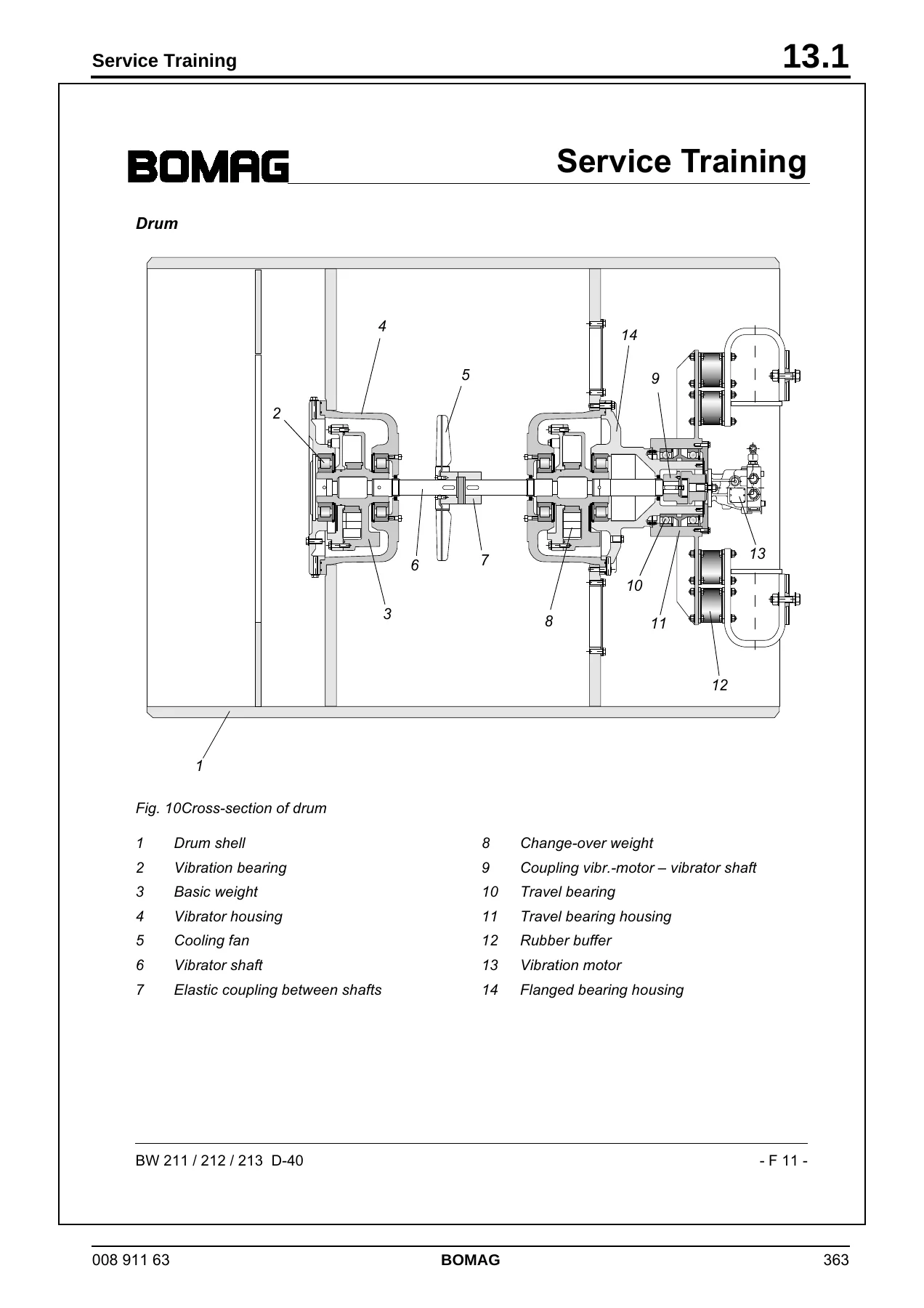
  • 18 Drum — Special Tools, Repair Overview, Removal and Installation, Repair, Change-Over Weight, Rubber Buffers
  • 19 Oscillating Articulated Joint — Special Tools, Repair Overview, Removal and Installation, Dismantling, Assembly
  • 20 Suppliers Documentation — Travel Pump (Sauer Series 90), Vibration Pump (Sauer Series 42), Drum Drive (Poclain MSE/MF MS2-18), Vibration Motor (A10FM/A10FE Series 5), Axle Drive Motor (Sauer Series 51), Steering Valve (Danfoss OSPB/OSPC/OSPF), Axle
  • 21 Circuit Diagrams — Hydraulic Diagrams 581 202 10 / 581 202 11, Wiring Diagrams 582 702 09 / 582 702 29 / 582 702 41 and Wiring Diagram 9

Complete PDF Bookmark Tree

Complete Bookmarks

The complete bookmarks in the “BOMAG BW 211 BW 212 BW 213 D-40 PD-40 Single Drum Roller Service Manual” are as follows:

BW 211 / 212 / 213 D-40p. 1
BW 211 / 212 / 213 PD-40p. 1
S/N 101 582 42 . . . . S/N 101 582 43 . . . . S/N 101 582 44 . . . . S/N 101 582 47 . . . . S/N 101 582 48 . . . .p. 1
S/N 101 582 49 . . . . S/N 101 582 55 . . . .p. 1
S/N 861 583 00 . . . . S/N 101 583 02 . . . . S/N 101 583 03 . . . . S/N 101 583 48 . . . . S/N 101 583 49 . . . .p. 1
S/N 101 583 50 . . . .p. 1
Single drum rollerp. 1
1 Generalp. 7
1 Generalp. 7
1.1 Introductionp. 8
This manual addresses the professionally qualified personnel or the after sales service of BOMAG, and should be of help and assistance in correct and efficient repair and maintenance work.p. 8
This manual describes the disassembly, dismantling, assembly, installation and repair of components and assemblies. The repair of components and assemblies is only described as this makes sense under due consideration of working means and spare parts…p. 8
Documentationp. 8
Documentationp. 8
For the BOMAG machines described in this manual the following documentation is additionally available:p. 8
1 Operating and maintenance instructionsp. 8
2 Spare parts cataloguep. 8
3 Wiring diagram*p. 8
4 Hydraulic diagram*p. 8
5 Service Informationp. 8
Use only genuine BOMAG spare parts.p. 8
Spare parts needed for repairs can be taken from the spare parts catalogue for the machine.p. 8
These repair instructions are not subject of an updating service; for this reason we would like to draw your attention to our additional "Technical Service Bulletins".p. 8
In case of a new release all necessary changes will be included.p. 8
In the course of technical development we reserve the right for technical modifications without prior notification.p. 8
Information and illustrations in this manual must not be reproduced and distributed, nor must they be used for the purpose of competition. All rights according to the copyright law remain expressly reserved.p. 8
These safety regulations must be read and applied by every person involved in the repair /maintenance of this machine. The applicable accident prevention instructions and the safety regulations in the operating and maintenance instructions must be ad…p. 8
BOMAG GmbHp. 8
Printed in Germanyp. 8
Copyright by BOMAGp. 8
* The applicable documents valid at the date of printing are part of this manual.p. 8
Generalp. 9
Safety regulationsp. 9
Important notesp. 9
Important notesp. 9
These safety regulations must be read and applied by every person involved in the repair /maintenance of this machine. The applicable accident prevention instructions and the safety regulations in the operating and maintenance instructions must be ad…p. 9
Repair work shall only performed by appropriately trained personnel or by the after sales service of BOMAG.p. 9
Workshop equipment and facilities as well as the use and waste disposal of fuels and lubricants, cleaning agents and solvent as well as gases and chemicals are subject to legal regulations, which are intended to provide a minimum on safety. It is obv…p. 9
This manual contains headers like "Note", "Attention", "Danger" and "Environment", which must be strictly complied with in order to inform about and avoid dangers to persons, property and the environment.p. 9
Paragraphs marked like this contain technical information for the optimal economical use of the machine.p. 9
Paragraphs marked like this highlight possible dangers for machines or parts of the machine.p. 9
Paragraphs marked like this highlight possible dangers for persons.p. 9
Paragraphs marked like this point out practices for safe and environmental disposal of fuels and lubricants as well as replacement parts.p. 9
Observe the regulations for the protection of the environment.p. 9
Generalp. 9
Generalp. 9
For repair and maintenance work move the machine on a firm base and shut it down.p. 9
Always secure the machine against unintended rolling.p. 9
Secure the engine reliably against unintentional starting.p. 9
Mark a defective machine and a machine under repair by attaching a clearly visible warning label to the dashboard.p. 9
Block the articulated joint with the articulation lock.p. 9
Use protective clothes like hard hat, safety boots and gloves.p. 9
Keep unauthorized persons away from the machine during repair work.p. 9
Tools, lifting gear, lifting tackle, supports and other auxiliary equipment must be fully functional and in safe condition.p. 9
Use only safe and approved lifting gear of sufficient load bearing capacity to remove and install parts or components from and to the machine.p. 9
Do not use easily inflammable or harmful substances, such as gasoline or paint thinners for cleaning.p. 9
Do not smoke or use open fire and avoid sparks when cleaning or repairing a tank.p. 9
When performing welding work strictly comply with the respective welding instructions.p. 9
Transport work with cranes and lifting tacklep. 9
Cranes must only be operated by instructed persons who had been trained in handling cranes.p. 9
Follow the operating instructions of the manufacturer when working with cranes.p. 9
Follow the operating instructions of the operator when working with cranes.p. 9
Always comply with the applicable accident prevention instructions when working with cranes and lifting tackle.p. 9
Precautions and codes of conduct for welding workp. 9
Welding work must only be carried out by properly trained personnel.p. 9
Electric shock!p. 9
Electric shock!p. 9
Sparks, fire hazard, burning of skin!p. 9
Infrared or ultraviolet radiation (arc), flashing of eyes!p. 9
Health hazard caused by welding work on highly alloyed work pieces, metal coatings, paint coatings, plastic coatings, oil containing dirt deposits, grease or solvent residues, etc.!p. 9
Check welding equipment and cables for damage before use (also the validity of inspection stickers).p. 9
Ensure good conductivity between ground cable and workpiece, avoid joints and bearings.p. 9
Start the extraction fan before starting work and guide with the progressing work as required.p. 10
Always isolate the burner when laying it down (remove possible electrode residues).p. 10
Protect cables from being damaged, use cables with insulated couplings.p. 10
Ensure sufficient fire protection, keep a fire extinguisher at hand.p. 10
Welding work in areas where there is a risk of fire or explosion, must only be carried out with welding permission.p. 10
Remove any combustible materials from the welding area or cover such items appropriately.p. 10
Name a fire watch during and after welding work.p. 10
Place welding rod holders and inert gas welding guns only on properly insulated bases.p. 10
Place the inert gas bottles in a safe place and secure them against falling over.p. 10
Use a protective screen or hand shield with welding filter, wear welding gloves and clothes.p. 10
Switch the welding unit off before connecting welding cables.p. 10
Check electrode holders and electric cables at regular intervals.p. 10
Behaviour in case of faultsp. 10
In case of faults on the welding unit switch of the welding unit immediately and have it repaired by expert personnel.p. 10
In case of failure of the extraction system switch the system off and have it repaired by expert personnel.p. 10
Maintenance; waste disposalp. 10
Replace damaged insulating jaws and welding rod holders immediately.p. 10
Replace the welding wire reels only in de-energized state.p. 10
What to do in case of accidents; First Aidp. 10
Keep calm.p. 10
Keep calm.p. 10
Call first air helpers.p. 10
Report the accident.p. 10
In case of an electric accident: Interrupt the power supply and remove the injured person from the electric circuit. If breathing and heart have stopped apply reactivation measures and call for an emergency doctor.p. 10
Old oilsp. 10
Old oilsp. 10
Prolonged and repetitive contact with mineral oils will remove the natural greases from the skin and causes dryness, irritation and dermatitis. Moreover, used engine oils contain potentially hazardous contaminants, which could cause skin cancer. Appr…p. 10
Wear protective clothes and safety gloves, if possible.p. 10
If there is a risk of eye contact you should protect your eyes appropriately, e.g. chemistry goggles or full face visor; a facility suitable for rinsing the eyes should also be available.p. 10
Avoid longer and repetitive contacts with oils. In case of open incisions and injuries seek medical advice immediately.p. 10
Apply protective cream before starting work, so that oil can be easier removed from the skin.p. 10
Wash affected skin areas with water and soap (skin cleansers and nail brushes will help). Lanolin containing agents will replace natural skin oils that were lost.p. 10
Do not use gasoline, kerosene, diesel, thinner or solvents to wash the skin.p. 10
Do not put oil soaked cloths into your pockets.p. 10
Avoid clothes getting soiled by oil.p. 10
Overalls must be washed at regular intervals. Dispose of non-washable clothes environmentally.p. 10
If possible degrease components before handling.p. 10
It is strictly prohibited to drain off oil into the soil, the sewer system or into natural waters. Old oil must be disposed of according to applicable environmental regulations. If in doubt you should consult your local authorities.p. 10
Hydraulicsp. 10
Hydraulicsp. 10
Always relieve the pressure in the hydraulic system before disconnecting any lines. Hydraulic oil escaping under pressure can penetrate the skin and cause severe injury.p. 10
Always make sure that all screw fittings have been tightened properly and that hoses and pipes are in mint condition before pressurizing the system again.p. 10
Hydraulic oil leaking out of a small opening can hardly be noticed, therefore please use a piece of cardboard or wood when checking for leaks. When injured by hydraulic oil escaping under pressure consult a physician immediately, as otherwise this ma…p. 10
Do not step in front of or behind the drums, wheels or crawler tracks when performing adjustment work in the hydraulic system while the engine is running. Block drums, wheels or crawler tracks with wedges.p. 10
Reattach all guards and safety installations after all work has been completed.p. 11
It is strictly prohibited to drain off oil into the soil, the sewer system or into natural waters. Oil oil must be disposed of according to applicable environmental regulations. If in doubt you should consult your local authorities.p. 11
Fuelsp. 11
Fuelsp. 11
Repair work shall only performed by appropriately trained personnel or by the after sales service of BOMAG.p. 11
Follow the valid accident prevention instructions when handling fuels.p. 11
The following notes refer to general safety precautions for danger free handling of fuel.p. 11
Fuel vapours not only are easily inflammable, but also highly explosive inside closed rooms and toxic; dilution with air creates an easily inflammable mixture. The vapours are heavier than air and therefore sink down to the ground. Inside a workshop …p. 11
Fire extinguishers charged with FOAM, COp. 11
2p. 11
The vehicle battery must always be disconnected, BEFORE work in the fuel system is started. Do not disconnect the battery while working on the fuel system. Sparks could cause explosion of the fuel fumes.p. 11
Wherever fuel is stored, filled, drained off or where work on fuel systems is carried out, all potential ignition sources must be extinguished or removed. Search lights must be fire proof and well protected against possible contact with running out fuelp. 11
Hot fuelsp. 11
Hot fuelsp. 11
Please apply the following measures before draining of fuel to prepare for repair work:p. 11
Allow the fuel to cool down, to prevent any contact with a hot fluid.p. 11
Vent the system, by removing the filler cap in a well ventilated area. Screw the filler cap back on, until the tank is finally emptied.p. 11
Synthetic rubberp. 11
Many O-rings, hoses, etc. are made of synthetic material, a so-called fluorocarbon elastomer. Under normal operating conditions this material is safe and does not impose any danger to health.p. 11
However, if this material becomes damaged by fire or extreme heat, it may decompose and form highly caustic hydrofluoric acid, which can cause severe burns in contact with skin.p. 11
If the material is in such a state it must only be touched with special protective gloves. The protective gloves must be disposed of according to applicable environmental regulations immediately after use.p. 11
If the material has contacted the skin despite these measures, take off the soiled clothes and seek medical advice immediately. In the meantime cool and wash the affected area of skin over a sufficient time with cold water or lime water.p. 11
Poisonous substancesp. 11
Some of the fluids and substances used are toxic and must under no circumstances be consumed.p. 11
Skin contact, especially with open wounds, must be avoided.p. 11
These fluids and substances are, amongst others, anti-freeze agents, hydraulic oils, fuels, washing additives, refrigerants, lubricants and various bonding agents.p. 11
Enginep. 11
Enginep. 11
Do not work on the fuel system while the engine is running. (Danger to life!)p. 11
Once the engine has stopped wait approx. 1 minutes for the system to depressurize. The systems are under high pressure. (Danger to life!)p. 11
Keep out of the danger zone during the initial test rung. Danger caused by high pressure in case of leaks. (Danger to life!)p. 11
When performing work on the fuel system make sure that the engine cannot be started unintentionally during repair work. (Danger to life!)p. 11
Maintenance and cleaning work on the engine must only be performed with the engine stopped and cooled down. Make sure that the electric system is switched off and sufficiently secured against being switched on again (e.g. pull off ignition key, attac…p. 11
Observe the accident prevention regulations for electric systems (e.g. -VDE-0100/-0101/-0104/- 0105 Electric precautions against dangerous contact voltages).p. 11
Cover all electric components properly before wet cleaning.p. 12
Air conditioning systemp. 12
Work on air conditioning systems must only be carried out by persons who can provide sufficient evidence of their ability (proof of professionalism) and only with the appropriate technical equipment.p. 12
Always wear goggles and protective clothing when performing maintenance and repair work on air conditioning systems. Refrigerant withdraws heat from the environment when evaporating, which can cause injury by freezing when in contact with skin (boili…p. 12
Perform maintenance and repair work on air conditioning systems only in well ventilated rooms! Escaping refrigerant vapours will mix with the ambient air and displace the oxygen required for breathing (danger of suffocating).p. 12
Smoking is prohibited when performing maintenance and repair work on air conditioning systems! Toxic breakdown products may be generated if refrigerant comes into contact with heat.p. 12
Refrigerant should always be extracted and removed by flushing with nitrogen before starting welding or soldering work near components of the air conditioning system. The development of heat may cause the refrigerant to develop toxic and highly corro…p. 12
Pungent smell! The toxic substances, which are responsible for the pungent smell, must not be inhaled, since this may cause damage to the respiratory system, the lung and other organs. Extract toxic breakdown products with a suitable extraction syste…p. 12
When blowing out components with compressed air and when flushing with nitrogen the gas mixture escaping from the components must be extracted via suitable extraction facilities (workshop extraction systems).p. 12
Handling pressure vesselsp. 12
Since the fluid container is pressurized, the manufacture and testing of these pressure vessels is governed by the pressure vessel directive. The pressure vessels must be repetitively tested by an expert as specified in TRB 532 Inspection by Experts,…p. 12
Secure pressure vessels against tipping over or rolling away.p. 12
Do not throw pressure vessels! Pressure vessels may thereby be deformed to such an extent, that they will crack. The sudden evaporation and escape of refrigerant releases excessive forces. This applies also when snapping off valves on bottles. Bottle…p. 12
Refrigerant bottles must never be placed near heating radiators. Higher temperatures will cause higher pressures, whereby the permissible pressure of the vessel may be exceeded.p. 12
Do not heat up refrigerant bottles with an open flame. Excessive temperatures can damage the material and cause the decomposition of refrigerant.p. 12
Do not overfill refrigerant bottles, since any temperature increase will cause enormous pressures.p. 12
It is strictly prohibited to release refrigerant into the atmosphere during operation, maintenance and repair work and when taking air conditioning systems into or out of service.p. 12
Batteryp. 12
Batteryp. 12
Always wear goggles and protective clothing to service or clean batteries! Battery acid can cause severe injury by cauterization when coming in contact with skin.p. 12
Work only well ventilated rooms (formation of oxyhydrogen gas).p. 12
Do not lean over the battery while it is under load, being charged or tested (danger of explosion).p. 12
Keep ignition sources away from the battery. Burning cigarettes, flames or sparks can cause explosion of the batteryp. 12
Use battery chargers etc. only in strict compliance with the operating instructions.p. 12
After an accident with acid flush the skin with a sufficient amount of water and seek medical advice.p. 12
Do not allow children access to batteries.p. 12
When mixing battery fluid always pour acid into water, never vice-versa.p. 12
Special safety regulationsp. 13
Use only genuine BOMAG spare parts for repair and maintenance work. Genuine spare parts and original accessories were specially developed, tested and approved for the machine.p. 13
The installation and use of non-genuine spare parts or non-genuine accessories may therefore have an adverse effect on the specific characteristics of the machine and thereby impair the active and/or passive driving safety. The manufacturer explicitl…p. 13
Unauthorized changes to the machine are prohibited for safety reasons.p. 13
Do not perform any cleaning work while the engine is running.p. 13
If tests on the articulated joint need to be performed with the engine running, do not stand in the articulation area of the machine (danger of crushing!).p. 13
If tests must be performed with the engine running do not touch rotating parts of the engine (danger of injury!).p. 13
Always ensure an adequate supply of fresh air when starting in closed rooms. Exhaust gases are highly dangerous!p. 13
Refuel only with the engine shut down. Ensure strict cleanliness and do not spill any fuel.p. 13
Always ensure an adequate supply of fresh air when refuelling in closed rooms.p. 13
Dispose of used filters in accordance with applicable environmental regulations.p. 13
When performing repair and maintenance work collect oils and fuels in suitable containers and dispose of in compliance with applicable environmental regulations.p. 13
Do not heat up oils higher than 160 °C because they may ignite.p. 13
Wipe off spilled or overflown oil using suitable cleaning means and dispose of in accordance with applicable environmental regulations.p. 13
Dispose of old batteries according to applicable environmental regulations.p. 13
There is a danger of scalding when draining off engine or hydraulic oil at operating temperature! Allow engine and hydraulic system to cool down to a sufficient level.p. 13
Do not exceed the max. permissible tire pressure.p. 13
The values specified in the table apply for screws:p. 14
General repair instructionsp. 14
Generalp. 14
Generalp. 14
Before removing or disassembling parts, assemblies, components or hoses mark these parts for easier assembly.p. 14
Before assembling and installing parts, assemblies or components oil or grease all movable parts or surfaces as required and in compliance with the compatibility of materials.p. 14
The values specified in the table apply for screws:p. 14
Electricsp. 14
Generalp. 14
Generalp. 14
Due to the fast technical development electric and electronic vehicle systems become more intelligent and more comprehensive day by day, and can hardly be dispensed with in hydraulic and mechanical vehicle systems.p. 14
Diagnostics according to planp. 14
Well structured trouble shooting procedures can save time and money.p. 14
Random tests have revealed that purely electronic components or control units only very rarely are the actual cause of failures:p. 14
In approx. 10 % of the examined cases the problems were caused by control units.p. 14
In approx. 15 % sensors and actuators were the cause of the problems.p. 14
By far the highest proportion of all faults could be traced back to wiring and connections (plugs, etc.).p. 14
General:p. 14
Before changing any expensive components, such as control units, you should run a systematic trouble shooting session to eliminate any other possible fault sources. Knowledge in basic electrics is required for this purpose. If a fault was diagnosed w…p. 14
Check for good cable and ground contacts, therefore keep all mechanical transition points between electric conductors (terminals, plugs) free of oxide and dirt, as far as this is possible.p. 14
Always use the machine related wiring diagram for testing. If one or more faults were detected, these should be corrected immediately.p. 14
Do not disconnect or connect battery or generator while the engine is running.p. 14
Do not operate the main battery switch under load.p. 14
Do not use jump leads after the battery has been removed.p. 14
Sensors and electric actuators on control units must never be connected individually or between external power sources for the purpose of testing, but only in connection with the control unit in question.p. 14
It is not permitted to pull plugs off while the voltage supply is switched on (terminal 15 "ON")! Switch the voltage supply "OFF" first and pull out the plug.p. 14
Even with an existing polarity reversal protection incorrect polarity must be strictly avoided. Incorrect polarity can cause damage to control units!p. 14
Plug-in connectors on control units are only dust and water tight if the mating connector is plugged on! Control units must be protected against spray water, until the mating connector is finally plugged on!p. 15
Unauthorized opening of control electronics (Microcontroller MC), modifications or repairs in the wiring can cause severe malfunctions.p. 15
Do not use any radio equipment or mobile phones in the vehicle cab without a proper aerial or in the vicinity of the control electronics!p. 15
Electrics and weldingp. 15
Before starting welding work you should disconnect the negative battery pole or interrupt the electric circuit with the main battery switch, disconnect the generator and pull the plugs off all control units in order to protect the electrical system o…p. 15
Disconnect the minus pole of the battery or interrupt the electric circuit with the main battery switch.p. 15
Isolate the generator and all control units from the electric circuit.p. 15
Always fasten the earth clamp of the welding unit in the immediate vicinity of the welding location.p. 15
When choosing the location for the earth clamp make sure that the welding current will not pass through joints or bearings.p. 15
The values specified in the table apply for screws:p. 15
Batteryp. 15
Rules for the handling of batteriesp. 15
When removing a battery always disconnect the minus pole before the plus pole. When installing the battery connect the minus pole after the plus pole to avoid short circuits.p. 15
Fasten the terminal clamps with a little force as possible.p. 15
Always keep battery poles and terminal clams clean to avoid high transition resistances when starting and the related development of heat.p. 15
Make sure the battery is properly fastened in the vehicle.p. 15
The values specified in the table apply for screws:p. 16
Generatorp. 16
Before removing the generator you must disconnect the ground cable from the minus pole of the battery while the ignition is switched off. Do not disconnect the generator while the engine is running, because this may cause extremely high voltage peaks…p. 16
When disassembling the battery cable, the B+-nut underneath on the generator side may also be loosened. This nut must in this case be retightened.p. 16
When connecting e.g. the battery cable to the terminal of the generator you must make sure that the polarity is correct (generator B+ to the + pole of the battery). Mixing up the polarities by mistake causes short circuit and damage to the rectifier …p. 16
The generator can only be operated with the battery connected. Under special conditions emergency operation without battery is permitted, the lifetime of the generator is in such cases especially limited.p. 16
Plus and minus cables must be disconnected during rapid charging of the battery or electric welding on the vehicle.p. 16
When cleaning the generator with a steam or water jet make sure not to direct the steam or water jet directly on or into the generator openings or ball bearings. After cleaning the generator should be operated for about 1 – 2 minutes to remove any de…p. 16
The values specified in the table apply for screws:p. 16
Starter motorp. 16
So-called jump starting (using an additional external battery) without the battery connected is dangerous. When disconnecting the cables from the poles high inductivities (arcs, voltage peaks) may occur and destroy the electrical installation.p. 16
For purposes like e.g. purging the fuel systems, starters may be operated for maximum 1 minute without interruption. Then you should wait for at least 30 minutes (cooling down) until trying again. During the 1 minute starting period this process shou…p. 16
Starter motors must not be cleaned with high pressure steam cleaning equipment.p. 16
The contacts on starter terminals 30, 45, 50 must be protected against unintended shorting (jump protection).p. 16
When replacing the starter the ring gear on the engine flywheel must be checked for damage and its number of teeth – if necessary replace the ring gear.p. 16
Always disconnect the battery before starting assembly work in the starter area of the engine or on the starter itself.p. 16
The values specified in the table apply for screws:p. 17
Hydraulic systemp. 17
Repair work on hydraulic elements shall only performed by appropriately trained personnel or by the after sales service of BOMAG.p. 17
Please notep. 17
Please notep. 17
Cleanliness is of utmost importance. Dirt and other contaminations must strictly be kept out of the system.p. 17
Connections and screw fittings, filler neck covers and their immediate surrounding areas must be cleaned before removal.p. 17
Before loosening hoses, pipe lines etc. relieve all pressure from the system.p. 17
During repair work keep all openings closed with clean plastic plugs and caps.p. 17
Never run pumps, motors and engines without oil or hydraulic oil.p. 17
When cleaning hydraulic components take care not to damage any fine machine surfaces.p. 17
Chemical and rubber soluble cleansing agents may only be used to clean metal parts. Do not let such substances come in contact with rubber parts.p. 17
Rinse of cleaned parts thoroughly, dry them with compressed air and apply anti-corrosion oil immediately. Do not install parts that show traces of corrosion.p. 17
Avoid the formation of rust on fine machined caused by hand sweat.p. 17
Use new O-rings or seal rings for reassembly.p. 17
Use only hydraulic oil as sliding agent when reassembling. Do not use any grease!p. 17
Use only the specified pressure gauges. Risk of damaging the pressure gauges under too high pressure.p. 17
Check the hydraulic oil level before and after the work.p. 17
Fill in only clean oil as specified in the maintenance instructions.p. 17
Check the hydraulic system for leaks, if necessary find and rectify the cause.p. 17
Before taking new hydraulic components into operation fill these with hydraulic oil as specified in the operating and maintenance instructions.p. 17
After changing a hydraulic component thoroughly flush, refill and bleed the complete hydraulic system.p. 17
Perform measurements at operating temperature of the hydraulic oil (approx. 40 ¯C).p. 17
After changing a component perform a high and charge pressure test, if necessary check the speed of the exciter shaft.p. 17
The operating pressure of the exciter shaft to a great extent depends on the base under the vibrating drum. On hard ground place the drums on a suitable base and check the drum pressure. Do not activate the vibration on a hard, concreted base, danger…p. 17
After the completion of all tests perform a test run and then check all connections and fittings for leaks with the engine still stopped and the hydraulic system depressurized.p. 17
Before commissioningp. 17
Fill the housings of hydraulic pumps and motors with hydraulic oil. Use only hydraulic oils according to the specification in the maintenance instructions.p. 17
After changing a component flush the hydraulic system as described in the flushing instructions.p. 17
Taking into operationp. 17
Bleed the hydraulic circuits.p. 17
Start up the hydraulic system without load.p. 17
Check the hydraulic oil level in the tank, if necessary top up with hydraulic oil as specified in the operating and maintenance instructions or drain oil off into a suitable container.p. 17
After taking into operationp. 17
Check fittings and flanges for leaks.p. 17
After each repair check all adjustment data, system pressures, rotational speeds and nominal values in the hydraulic system, adjust if necessary.p. 17
Do not adjust pressure relief valves and control valves to values above their specified values.p. 17
The values specified in the table apply for screws:p. 18
Air conditioning systemp. 18
Chemicals/ozone layer regulationp. 18
The chemicals/ozone layer regulation, which became effective on 01.12.2006, supplements the still directly applicable regulation (EG) no. 2037/2000 from 29.06.2000 concerning substances, which cause decomposition of the ozone layer and at the same ti…p. 18
Work on air conditioning systems must only be carried out by persons who:p. 18
have proven to have sufficient expert knowledge,p. 18
have the necessary equipment to undertake such tasks,p. 18
are reliable andp. 18
are not any directives regarding their activities when carrying out inspection and maintenance work acc. to § 4 section 2 of the chemical/ozone layer regulation.p. 18
The inspection and maintenance tasks, including leak tests and possible repair activities, must be recorded in the operating instructions together with information about the refrigerant quantities used and regained, whereby the operator is obliged to…p. 18
Cleanliness is of utmost importance. Dirt and other contaminations must strictly be kept out of the system.p. 18
Tools used on refrigeration circuits must be of excellent condition, thus to avoid the damage of any connections.p. 18
During repairs on refrigerant lines and components, these must be kept closed, as far as this is possible, to prevent the system from being contaminated by air, moisture and dirt. The operational safety of the system can only be assured as long as al…p. 18
Connections, screw fittings and their immediate surrounding areas must be cleaned before removal.p. 18
Before loosening hoses, pipe lines etc. relieve all pressure from the system.p. 18
During repair work keep all openings closed with clean plastic plugs and caps.p. 18
All parts to be reused should be cleaned with a gasoline free solvent and blow-dried with clean compressed air or dried with a lint-free cloth.p. 18
Before opening all components should have warmed up to ambient temperature, to avoid that damp air is drawn into the component by the difference in temperatures.p. 18
Damaged or leaking parts of the air conditioning must not be repaired by welding or soldering, but must generally be replaced.p. 18
Do not fill up refrigerant, but extract existing refrigerant and refill the system.p. 18
Different types of refrigerant must not be mixed. Only the refrigerant specified for the corresponding air conditioning system must be used.p. 18
Refrigerant circuits with refrigerant type R134a must only be operated with the compressor oil / refrigeration oil approved for the compressor.p. 18
Used compressor oil/refrigeration oil must be disposed of in strict compliance with applicable environmental regulations.p. 18
Due to its chemical properties compressor oil / refrigeration oil must never be disposed of together with engine or transmission oil.p. 18
Compressor oil / refrigeration oil is highly hydroscopic. Oil cans must strictly be kept closed until use. Oil rests should not be used, if the can had been opened over a longer period of time.p. 18
All O-rings/seal rings as well as pipe/ hose fittings must be oiled with compressor/refrigeration oil bfore assembly.p. 18
When replacing a heat exchanger, e.g. evaporator or condenser, any compressor oil/refrigeration oil lost by exchanging the components, must be replaced with fresh oil.p. 18
A too high compressor oil / refrigeration oil level adversely affects the cooling performance and a too low oil level has a negative effect on the lifetime of the compressor.p. 18
Use new O-rings or seal rings for reassembly.p. 18
Always used 2 spanners to work on pipes/hoses to avoid damages .p. 18
Tighten screw fittings with the specified torque.p. 18
Check all pipes/hoses, screw fittings or components for damage, replace if necessary.p. 18
Do not leave the refrigerant circuit unnecessarily open to the atmosphere.p. 18
In case of a repair on the refrigeration system you should first evacuate the air conditioning system for at least 45 minutes to remove any moisture from the system, before you start to refill. Moisture bonded in the compressor oil / refrigeration oi…p. 18
Compressor valves must only be opened after the system has been properly sealed.p. 18
The use of leak detection spray is not permitted. If such substances are used the WARRANTY will become null and void.p. 18
If the air conditioning system had been opened for repair work, a new drier should be installed in the refrigerant circuit.p. 19
After completion of repair work screw locking caps (with seals) on all valve connections service connections.p. 19
Before start up of the air conditioning system after a new filling: – Turn the compressor approx. 10 revolutions by hand using the clutch or V-belt pulley of the magnetic clutch. – Start the engine with the compressor/control valve switched off. – On…p. 19
Never run the compressor with an insufficient amount of refrigerant.p. 19
The values specified in the table apply for screws:p. 19
Fuel hosesp. 19
Fig. 1p. 19
All fuel hoses have two layers of material, a reinforced rubber coating outside and an internal Viton hose. If a fuel hose has come loose one must make absolutely sure that the internal Viton layer has not been separated from the reinforced outer lay…p. 19
The values specified in the table apply for screws:p. 20
Gaskets and mating surfacesp. 20
Leaking sealing faces can mostly be traced back to incorrect assembly of seals and gaskets.p. 20
Before assembling a new seal or gasket make sure that the sealing surface is free of pitting, flutes, corrosion or other damage.p. 20
Inappropriately stored or handled seals (e.g. hanging from hooks or nails) must under no circumstances be used.p. 20
Assemble seals and gaskets only with sealing compound, grease or oil, if this is specifically specified in the repair instructions.p. 20
If necessary remove any old sealing compound before assembling. For this purpose do not use any tools that could damage the sealing surfaces.p. 20
Sealing compound must be applied thin and evenly on the corresponding surfaces; take care that the compound does not enter into oil galleries or blind threaded bores.p. 20
Examine the contact faces for scratches and burrs, remove these with a fine file or an oilstone; take care that no grinding dust and dirt enters into tapped bores or enclosed components.p. 20
Blow out lines, ducts and gaps with compressed air, replace any O-rings and seals that have been dislodged by the compressed air.p. 20
Assembly of radial sealsp. 20
Fig. 2p. 20
Lubricate the sealing lips (2)p. 20
(Fig. 2)p. 20
Slide the seal over the shaft, with the lip facing towards the fluid to be sealed.p. 20
If possible, use an assembly sleeve (1p. 20
(Fig. 2)p. 20
to protect the lip from being damaged by sharp edges, threads or splines.p. 20
Lubricate the outer rim (arrow 3p. 20
(Fig. 2)p. 20
Fig. 3p. 20
Press or knock the seal into the housing, until it is flush with the housing surface.p. 20
If possible, use a "bell" (1p. 20
(Fig. 3)p. 20
that the seal will not skew.p. 20
If you have no proper service tools at hand, use a suitable drift punch with a diameter which is about 0,4 mm smaller than the outer diameter of the seal. Use VERY LIGHT blows with the hammer if no press is available.p. 20
The values specified in the table apply for screws:p. 21
Feather keys and keywaysp. 21
Feather keys may only be reused if they are free of damage.p. 21
Fig. 4p. 21
Clean and thoroughly examine the feather key.p. 21
Deburr and thoroughly clean the edges of the keyway with a fine file before reassembling.p. 21
The values specified in the table apply for screws:p. 21
Ball and roller bearingsp. 21
Ball and roller bearings may only be reused if they are free of damage and do not show any signs of wear.p. 21
Fig. 5p. 21
If a ball or roller bearing of a bearing pair shows defects, both ball or roller bearings need to be replaced.p. 21
Remove any lubricant residues from the ball or roller bearing to be examined by washing it with gasoline or any other appropriate degreasing agent. Ensure strict cleanliness.p. 21
Check balls or rollers, running surfaces, outer faces of outer races and inner faces of inner races for visible damage. Replace the ball or roller bearing if necessary.p. 21
Check the ball or roller bearing for clearance and resistance between the inner and outer races, replace if necessary.p. 21
Lubricate the ball or roller bearing with the recommended type of grease before assembly or reassembly.p. 21
On greased bearings (e.g. wheel bearings) fill the space between ball or roller bearing and outer seal with the recommended type of grease before assembling the seal.p. 21
Check shaft and bearing housing for discolouration or other signs of movement between ball or roller bearing and seats.p. 22
Make sure that shaft and housing are free of burrs before assembling the ball or roller bearing.p. 22
Always mark the individual parts of separable ball or roller bearings (e.g. taper roller bearings) to enable correct reassembling. Never assemble the rollers to an outer race that has already been used, replace the complete ball or roller bearing ins…p. 22
Fig. 6p. 22
When assembling the ball or roller bearing to the shaft load must only be applied to the inner race 1p. 22
(Fig. 6)p. 22
When fitting the bearing into the housing load must only be applied to the outer race (2).p. 22
The values specified in the table apply for screws:p. 22
Screws and nutsp. 22
Tightening torquep. 22
Tighten nuts or screws with the tightening torques specified in the following tables of tightening torques. Tightening torques deviating from the ones in the table are specially mentioned in the repair instructions.p. 22
Damaged screws must under no circumstances be used any longer. Recutting threads with thread cutters or taps adversely affects the strength and leak tightness of the screw joint. Damaged or corroded thread pitches can cause incorrect torque value rea…p. 22
Self-locking nuts must generally be replaced after disassembly.p. 22
The use of screws with too high strength can cause damage!p. 22
Nut of a higher strength can generally be used instead of nuts of a lower strength classification.p. 22
When checking or retightening screw joints to the specified tightening torque you should first relieve by a quarter turn and then tighten to the correct torque.p. 22
Before tightening you should lightly oil the thread, in order to ensure low friction movement.p. 22
The same applies for self-locking nuts.p. 22
Make sure that no oil or grease will enter into blind tapped bores. The hydraulic power generated when turning in the screw could cause breakage of the effected part.p. 22
Strength classes, metric screwsp. 23
The strength classes (from 3.6 to 12.9) are specified for all strength classes from a nominal diameter of 5mm. The corresponding identification can be found where allowed for by the shape of the screw.p. 23
Fig. 7 Identification of screwsp. 23
Example: A screw is identified with 12.9.p. 23
The first number corresponds with 1/100 of the nominal tensile strength (minimum tensile strength) in N/ mmp. 23
2p. 23
The nominal tensile strength is 12 X 100 N/mmp. 23
2p. 23
2p. 23
The second number specifies 10-times the ration between lower yield point and nominal tensile strength (yield point ratio).p. 23
When exceeding the lower yield point, the material will return to its original shape when being relieved (plastic deformation).p. 23
When exceeding the upper yield point the material will not restore its original shape after being relieved.p. 23
The lower tensile strength is 9/10 X 1200 N/mmp. 23
2p. 23
2p. 23
However, these values are by no means identical with the tightening torques, which are to be set on a torque wrench. The corresponding calculation requires a higher effort and, in the end, depends on the materials to be bolted together.p. 23
Strength classes of metric nutsp. 23
Nuts are differentiated by three load groups. Each load group has a special designation system for the strength class assigned, so that the load group can be clearly identified.p. 23
Nuts for screw joints with full load capability (4, 5, 6, 8, 10, 12)p. 23
Fig. 8 Identification of nutsp. 23
In a connection with a screw, these nuts 1p. 23
(Fig. 8)p. 23
Nut height above 0.8 d (d = nominal dimension).p. 23
Strength class of nutp. 23
Strength class of associated screwp. 23
4p. 23
4p. 23
3.6, 4.6, 4.8p. 23
3.6, 4.6, 4.8p. 23
5p. 23
5p. 23
3.6, 4.6, 4.8p. 23
3.6, 4.6, 4.8p. 23
5.6, 5.8p. 23
6p. 23
6p. 23
6.8p. 23
6.8p. 23
8p. 23
8p. 23
8.8p. 23
8.8p. 23
9p. 23
9p. 23
9.8p. 23
9.8p. 23
10p. 23
10p. 23
10.8p. 23
10.8p. 23
12p. 23
12p. 23
12.8p. 23
12.8p. 23
Nuts for screw joints with limited load factor (04, 05)p. 23
The preceding "0" indicates that, due to their low height, nuts 2p. 23
(Fig. 8)p. 23
Nut height below 0,8 d (d = nominal dimension).p. 23
Nuts for screw joints without specified load factor (11H, 14H, 17H, 22H)p. 23
This standard contains strength classes (hardness classes) for nuts 3p. 23
(Fig. 8)p. 23
Nut height below 0,5 d (d = nominal dimension).p. 23
Identification in clock systemp. 24
Fig. 9 Identification of nuts in clock systemp. 24
For small nutsp. 24
(Fig. 9)p. 24
The 12 o'clock position is identified by a dot or the manufacturer's symbol.p. 24
The strength class is identified by a dash (b).p. 24
Identification of UNF-threadsp. 24
Fig. 10p. 24
Screwsp. 24
The screw head is marked with a stamped in, round cavity 3p. 24
(Fig. 10)p. 24
Nutsp. 24
An uninterrupted series of stamped in circles parallel to the axis of the nut on a hexagon area (2).p. 24
Studs and brake rodsp. 24
At the outmost end a short end of the component is reduced to its core diameter (1).p. 24
Cotter pinsp. 25
Fig. 11p. 25
In places where cotter pins are used, these must be reassembled. Cotter pins must generally be renewed after disassembly.p. 25
Cotter pins must be assembled as shown in the illustration, unless specified differently.p. 25
The values specified in the table apply for screws:p. 26
Tightening torquesp. 26
The values specified in the table apply for screws:p. 26
black oiledp. 26
black oiledp. 26
with surface protection A4Cp. 26
with surface protection DACROMETp. 26
DACROMET is a surface protection that mainly consists of zinc and aluminium in a chromium oxide matrix. DACROMETIZATION provides excellent corrosion protection for metal surfaces by applying a mineral coating with metallic-silver appearance.p. 26
Tightening torques for screws with metric unified threadp. 26
Coefficient of friction m tot. = 0,14p. 26
mp. 26
Screw dimensionp. 26
Tightening torques Nmp. 26
8.8p. 26
8.8p. 26
10.9p. 26
10.9p. 26
12.9p. 26
12.9p. 26
M4p. 26
M4p. 26
3p. 26
3p. 26
5p. 26
5p. 26
5p. 26
5p. 26
M5p. 26
M5p. 26
6p. 26
6p. 26
9p. 26
9p. 26
10p. 26
10p. 26
M6p. 26
M6p. 26
10p. 26
10p. 26
15p. 26
15p. 26
18p. 26
18p. 26
M8p. 26
M8p. 26
25p. 26
25p. 26
35p. 26
35p. 26
45p. 26
45p. 26
M10p. 26
M10p. 26
50p. 26
50p. 26
75p. 26
75p. 26
83p. 26
83p. 26
M12p. 26
M12p. 26
88p. 26
88p. 26
123p. 26
123p. 26
147p. 26
147p. 26
M14p. 26
M14p. 26
137p. 26
137p. 26
196p. 26
196p. 26
235p. 26
235p. 26
M16p. 26
M16p. 26
211p. 26
211p. 26
300p. 26
300p. 26
358p. 26
358p. 26
M18p. 26
M18p. 26
290p. 26
290p. 26
412p. 26
412p. 26
490p. 26
490p. 26
M20p. 26
M20p. 26
412p. 26
412p. 26
578p. 26
578p. 26
696p. 26
696p. 26
M22p. 26
M22p. 26
560p. 26
560p. 26
785p. 26
785p. 26
942p. 26
942p. 26
M24p. 26
M24p. 26
711p. 26
711p. 26
1000p. 26
1000p. 26
1200p. 26
1200p. 26
M27p. 26
M27p. 26
1050p. 26
1050p. 26
1480p. 26
1480p. 26
1774p. 26
1774p. 26
M30p. 26
M30p. 26
1420p. 26
1420p. 26
2010p. 26
2010p. 26
2400p. 26
2400p. 26
Tightening torques for screws with metric unified fine threadp. 26
Coefficient of friction m tot. = 0,14p. 26
mp. 26
Screw dimensionp. 26
Tightening torques Nmp. 26
8.8p. 26
8.8p. 26
10.9p. 26
10.9p. 26
12.9p. 26
12.9p. 26
M8 x 1p. 26
M8 x 1p. 26
26p. 26
26p. 26
37p. 26
37p. 26
48p. 26
48p. 26
M10 x 1.25p. 26
M10 x 1.25p. 26
52p. 26
52p. 26
76p. 26
76p. 26
88p. 26
88p. 26
M12 x 1,25p. 26
M12 x 1,25p. 26
98p. 26
98p. 26
137p. 26
137p. 26
126p. 26
126p. 26
M12 x 1.5p. 26
M12 x 1.5p. 26
93p. 26
93p. 26
127p. 26
127p. 26
152p. 26
152p. 26
M14 x 1.5p. 26
M14 x 1.5p. 26
152p. 26
152p. 26
216p. 26
216p. 26
255p. 26
255p. 26
M16 x 1.5p. 26
M16 x 1.5p. 26
225p. 26
225p. 26
318p. 26
318p. 26
383p. 26
383p. 26
M18 x 1.5p. 26
M18 x 1.5p. 26
324p. 26
324p. 26
466p. 26
466p. 26
554p. 26
554p. 26
M20 x 1.5p. 26
M20 x 1.5p. 26
461p. 26
461p. 26
628p. 26
628p. 26
775p. 26
775p. 26
M22 x 1.5p. 26
M22 x 1.5p. 26
618p. 26
618p. 26
863p. 26
863p. 26
1058p. 26
1058p. 26
M24 x 2p. 26
M24 x 2p. 26
780p. 26
780p. 26
1098p. 26
1098p. 26
1294p. 26
1294p. 26
M27 x2p. 26
M27 x2p. 26
1147p. 26
1147p. 26
1578p. 26
1578p. 26
1920p. 26
1920p. 26
M30 x 2p. 26
M30 x 2p. 26
1568p. 26
1568p. 26
2254p. 26
2254p. 26
2695p. 26
2695p. 26
Tightening torques for screws treated with anti-seizure paste OKS 240 (copper paste)p. 27
Tightening torques for screws treated with anti-seizure paste OKS 240p. 27
Anti-seizure paste (copper paste) is used for the assembly of screw connections, which are exposed to high temperatures and corrosive effects. Prevents seizure and corrosion.p. 27
Screw dimensionp. 27
Tightening torques Nmp. 27
8.8p. 27
8.8p. 27
10.9p. 27
10.9p. 27
12.9p. 27
12.9p. 27
M16p. 27
M16p. 27
169p. 27
169p. 27
240p. 27
240p. 27
287p. 27
287p. 27
M16 x 1.5p. 27
M16 x 1.5p. 27
180p. 27
180p. 27
255p. 27
255p. 27
307p. 27
307p. 27
M18p. 27
M18p. 27
232p. 27
232p. 27
330p. 27
330p. 27
392p. 27
392p. 27
M18 x 1.5p. 27
M18 x 1.5p. 27
260p. 27
260p. 27
373p. 27
373p. 27
444p. 27
444p. 27
M20p. 27
M20p. 27
330p. 27
330p. 27
463p. 27
463p. 27
557p. 27
557p. 27
M20 x 1.5p. 27
M20 x 1.5p. 27
369p. 27
369p. 27
502p. 27
502p. 27
620p. 27
620p. 27
M22p. 27
M22p. 27
448p. 27
448p. 27
628p. 27
628p. 27
754p. 27
754p. 27
M22 x 1.5p. 27
M22 x 1.5p. 27
495p. 27
495p. 27
691p. 27
691p. 27
847p. 27
847p. 27
M24p. 27
M24p. 27
569p. 27
569p. 27
800p. 27
800p. 27
960p. 27
960p. 27
M24 x 2p. 27
M24 x 2p. 27
624p. 27
624p. 27
879p. 27
879p. 27
1036p. 27
1036p. 27
M27p. 27
M27p. 27
840p. 27
840p. 27
1184p. 27
1184p. 27
1520p. 27
1520p. 27
M27 X 2p. 27
M27 X 2p. 27
918p. 27
918p. 27
1263p. 27
1263p. 27
1536p. 27
1536p. 27
M30p. 27
M30p. 27
1136p. 27
1136p. 27
1608p. 27
1608p. 27
1920p. 27
1920p. 27
M30 x 2p. 27
M30 x 2p. 27
1255p. 27
1255p. 27
1804p. 27
1804p. 27
2156p. 27
2156p. 27
3/4“ – 10 UNCp. 27
3/4“ – 10 UNCp. 27
276p. 27
276p. 27
388p. 27
388p. 27
464p. 27
464p. 27
3/4“ – 16 UNCp. 27
3/4“ – 16 UNCp. 27
308p. 27
308p. 27
432p. 27
432p. 27
520p. 27
520p. 27
Tightening torques for wheel nuts (fine thread)p. 27
Coefficient of friction m tot. = 0,14p. 27
mp. 27
These values result in a 90% utilization of the yield pointp. 27
Thread diameterp. 27
Tightening torques Nmp. 27
10.9p. 27
10.9p. 27
M12x1.5p. 27
M12x1.5p. 27
100p. 27
100p. 27
M14x1.5p. 27
M14x1.5p. 27
150p. 27
150p. 27
M18x1.5p. 27
M18x1.5p. 27
300 – 350p. 27
300 – 350p. 27
M20x1.5p. 27
M20x1.5p. 27
400 – 500p. 27
400 – 500p. 27
M22x1.5p. 27
M22x1.5p. 27
500 – 600p. 27
500 – 600p. 27
The values specified in the table apply for screws:p. 28
black oiledp. 28
black oiledp. 28
with surface protection A4Cp. 28
with surface protection DACROMETp. 28
The difference between Withworth and UNF/UNC threads is the fact that UNF and UNC threads have 60° flanks, as the metric ISO-thread, whereas Withworth has a flank of only 55°.p. 28
DACROMET is a surface protection that mainly consists of zinc and aluminium in a chromium oxide matrix. DACROMETIZATION provides excellent corrosion protection for metal surfaces by applying a mineral coating with metallic-silver appearance.p. 28
Tightening torques for screws with UNC thread, UNC Unified Coarse Thread Series, American Unified Coarse Threadp. 28
Tightening torques for screws with UNC thread,p. 28
Coefficient of friction m tot. = 0,14p. 28
mp. 28
UNC Unified Coarse Thread Series, American Unified Coarse Threadp. 28
Screw dimensionp. 28
Tightening torques Nmp. 28
8.8p. 28
8.8p. 28
10.9p. 28
10.9p. 28
12.9p. 28
12.9p. 28
1/4“ – 20p. 28
1/4“ – 20p. 28
11p. 28
11p. 28
15p. 28
15p. 28
19p. 28
19p. 28
5/16“ – 18p. 28
5/16“ – 18p. 28
23p. 28
23p. 28
32p. 28
32p. 28
39p. 28
39p. 28
3/8“ – 16p. 28
3/8“ – 16p. 28
39p. 28
39p. 28
55p. 28
55p. 28
66p. 28
66p. 28
7/16“ – 14p. 28
7/16“ – 14p. 28
62p. 28
62p. 28
87p. 28
87p. 28
105p. 28
105p. 28
1/2“ – 13p. 28
1/2“ – 13p. 28
96p. 28
96p. 28
135p. 28
135p. 28
160p. 28
160p. 28
9/16“ – 12p. 28
9/16“ – 12p. 28
140p. 28
140p. 28
200p. 28
200p. 28
235p. 28
235p. 28
5/8“ – 11p. 28
5/8“ – 11p. 28
195p. 28
195p. 28
275p. 28
275p. 28
330p. 28
330p. 28
3/4“ – 10p. 28
3/4“ – 10p. 28
345p. 28
345p. 28
485p. 28
485p. 28
580p. 28
580p. 28
7/8“ – 9p. 28
7/8“ – 9p. 28
560p. 28
560p. 28
770p. 28
770p. 28
940p. 28
940p. 28
1“ – 8p. 28
1“ – 8p. 28
850p. 28
850p. 28
1200p. 28
1200p. 28
1450p. 28
1450p. 28
1 1/8“ – 7p. 28
1 1/8“ – 7p. 28
1200p. 28
1200p. 28
1700p. 28
1700p. 28
2000p. 28
2000p. 28
1 1/4“ – 7p. 28
1 1/4“ – 7p. 28
1700p. 28
1700p. 28
2400p. 28
2400p. 28
2900p. 28
2900p. 28
1 3/8“ – 6p. 28
1 3/8“ – 6p. 28
2200p. 28
2200p. 28
3100p. 28
3100p. 28
3700p. 28
3700p. 28
1 1/2“ – 6p. 28
1 1/2“ – 6p. 28
3000p. 28
3000p. 28
4200p. 28
4200p. 28
5100p. 28
5100p. 28
Tightening torques for screws with UNF thread, UNF Unified National Fine Thread Series, American Unified Fine Threadp. 28
Tightening torques for screws with UNF thread,p. 28
Coefficient of friction m tot. = 0,14p. 29
mp. 29
UNF Unified National Fine Thread Series, American Unified Fine Threadp. 28
Screw dimensionp. 28
Tightening torques Nmp. 28
8.8p. 28
8.8p. 28
10.9p. 28
10.9p. 28
12.9p. 28
12.9p. 28
1/4“ – 28p. 28
1/4“ – 28p. 28
13p. 28
13p. 28
18p. 28
18p. 28
22p. 28
22p. 28
5/16“ – 24p. 28
5/16“ – 24p. 28
25p. 28
25p. 28
35p. 28
35p. 28
42p. 28
42p. 28
3/8“ – 24p. 28
3/8“ – 24p. 28
45p. 28
45p. 28
63p. 28
63p. 28
76p. 28
76p. 28
7/16“ – 20p. 28
7/16“ – 20p. 28
70p. 28
70p. 28
100p. 28
100p. 28
120p. 28
120p. 28
1/2“ – 20p. 28
1/2“ – 20p. 28
110p. 28
110p. 28
155p. 28
155p. 28
185p. 28
185p. 28
9/16“ – 18p. 28
9/16“ – 18p. 28
155p. 28
155p. 28
220p. 28
220p. 28
260p. 28
260p. 28
5/8“ – 18p. 28
5/8“ – 18p. 28
220p. 28
220p. 28
310p. 28
310p. 28
370p. 28
370p. 28
3/4“ – 16p. 28
3/4“ – 16p. 28
385p. 28
385p. 28
540p. 28
540p. 28
650p. 28
650p. 28
7/8“ -14p. 28
7/8“ -14p. 28
620p. 28
620p. 28
870p. 28
870p. 28
1050p. 28
1050p. 28
1“ – 12p. 29
1“ – 12p. 29
930p. 29
930p. 29
1300p. 29
1300p. 29
1600p. 29
1600p. 29
1 1/8“ – 12p. 29
1 1/8“ – 12p. 29
1350p. 29
1350p. 29
1900p. 29
1900p. 29
2300p. 29
2300p. 29
1 1/4“ – 12p. 29
1 1/4“ – 12p. 29
1900p. 29
1900p. 29
2700p. 29
2700p. 29
3200p. 29
3200p. 29
1 3/8“ – 12p. 29
1 3/8“ – 12p. 29
2600p. 29
2600p. 29
3700p. 29
3700p. 29
4400p. 29
4400p. 29
1 1/2“ – 12p. 29
1 1/2“ – 12p. 29
3300p. 29
3300p. 29
4600p. 29
4600p. 29
5600p. 29
5600p. 29
2 Technical datap. 31
Technical datap. 32
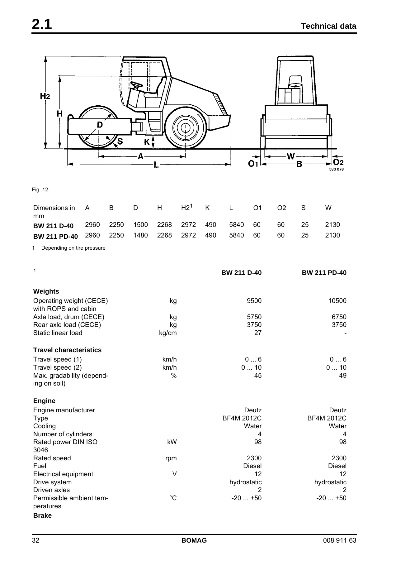
Fig. 12p. 32
Dimensions in mmp. 32
Ap. 32
Ap. 32
Bp. 32
Bp. 32
Dp. 32
Dp. 32
Hp. 32
Hp. 32
H2p. 32
H2p. 32
Depending on tire pressurep. 32
Kp. 32
Kp. 32
Lp. 32
Lp. 32
O1p. 32
O1p. 32
O2p. 32
O2p. 32
Sp. 32
Sp. 32
Wp. 32
Wp. 32
BW 211 D-40p. 32
BW 211 D-40p. 32
2960p. 32
2960p. 32
2250p. 32
2250p. 32
1500p. 32
1500p. 32
2268p. 32
2268p. 32
2972p. 32
2972p. 32
490p. 32
490p. 32
5840p. 32
5840p. 32
60p. 32
60p. 32
60p. 32
60p. 32
25p. 32
25p. 32
2130p. 32
2130p. 32
BW 211 PD-40p. 32
BW 211 PD-40p. 32
2960p. 32
2960p. 32
2250p. 32
2250p. 32
1480p. 32
1480p. 32
2268p. 32
2268p. 32
2972p. 32
2972p. 32
490p. 32
490p. 32
5840p. 32
5840p. 32
60p. 32
60p. 32
60p. 32
60p. 32
25p. 32
25p. 32
2130p. 32
2130p. 32
The right for technical modifications remains reservedp. 32
The right for technical modifications remains reservedp. 33
BW 211 D-40p. 32
BW 211 D-40p. 32
BW 211 PD-40p. 32
BW 211 PD-40p. 32
Weightsp. 32
Weightsp. 32
Operating weight (CECE) with ROPS and cabinp. 32
kgp. 32
kgp. 32
9500p. 32
9500p. 32
10500p. 32
10500p. 32
Axle load, drum (CECE)p. 32
kgp. 32
kgp. 32
5750p. 32
5750p. 32
6750p. 32
6750p. 32
Rear axle load (CECE)p. 32
kgp. 32
kgp. 32
3750p. 32
3750p. 32
3750p. 32
3750p. 32
Static linear loadp. 32
kg/cmp. 32
kg/cmp. 32
27p. 32
27p. 32
p. 32
p. 32
Travel characteristicsp. 32
Travel speed (1)p. 32
km/hp. 32
km/hp. 32
0 … 6p. 32
0 … 6p. 32
0 … 6p. 32
0 … 6p. 32
Travel speed (2)p. 32
km/hp. 32
km/hp. 32
0 … 10p. 32
0 … 10p. 32
0 … 10p. 32
0 … 10p. 32
Max. gradability (depending on soil)p. 32
%p. 32
%p. 32
45p. 32
45p. 32
49p. 32
49p. 32
Enginep. 32
Enginep. 32
Engine manufacturerp. 32
Deutzp. 32
Deutzp. 32
Deutzp. 32
Deutzp. 32
Typep. 32
Typep. 32
BF4M 2012Cp. 32
BF4M 2012Cp. 32
BF4M 2012Cp. 32
BF4M 2012Cp. 32
Coolingp. 32
Coolingp. 32
Waterp. 32
Waterp. 32
Waterp. 32
Waterp. 32
Number of cylindersp. 32
4p. 32
4p. 32
4p. 32
4p. 32
Rated power DIN ISO 3046p. 32
kWp. 32
kWp. 32
98p. 32
98p. 32
98p. 32
98p. 32
Rated speedp. 32
Rated speedp. 32
rpmp. 32
rpmp. 32
2300p. 32
2300p. 32
2300p. 32
2300p. 32
Fuelp. 32
Fuelp. 32
Dieselp. 32
Dieselp. 32
Dieselp. 32
Dieselp. 32
Electrical equipmentp. 32
Vp. 32
Vp. 32
12p. 32
12p. 32
12p. 32
12p. 32
Drive systemp. 32
Drive systemp. 32
hydrostaticp. 32
hydrostaticp. 32
hydrostaticp. 32
hydrostaticp. 32
Driven axlesp. 32
Driven axlesp. 32
2p. 32
2p. 32
2p. 32
2p. 32
Permissible ambient temperaturesp. 32
°Cp. 32
°Cp. 32
-20 … +50p. 32
-20 … +50p. 32
-20 … +50p. 32
-20 … +50p. 32
Brakep. 32
Brakep. 32
Service brakep. 33
Service brakep. 33
hydrostaticp. 33
hydrostaticp. 33
hydrostaticp. 33
hydrostaticp. 33
Parking brakep. 33
Parking brakep. 33
hydr.-mech.p. 33
hydr.-mech.p. 33
hydr.-mech.p. 33
hydr.-mech.p. 33
Steeringp. 33
Steeringp. 33
Type of steeringp. 33
articulatedp. 33
articulatedp. 33
articulatedp. 33
articulatedp. 33
Steering operationp. 33
hydrostaticp. 33
hydrostaticp. 33
hydrostaticp. 33
hydrostaticp. 33
Vibrationp. 33
Vibrationp. 33
Vibrating drump. 33
Vibrating drump. 33
1p. 33
1p. 33
1p. 33
1p. 33
Drive systemp. 33
Drive systemp. 33
hydrostaticp. 33
hydrostaticp. 33
hydrostaticp. 33
hydrostaticp. 33
Frequencyp. 33
Frequencyp. 33
Hzp. 33
Hzp. 33
30/36p. 33
30/36p. 33
30/36p. 33
30/36p. 33
Amplitudep. 33
Amplitudep. 33
mmp. 33
mmp. 33
1.8/0.9p. 33
1.8/0.9p. 33
1.64/0.82p. 33
1.64/0.82p. 33
Tiresp. 33
Tiresp. 33
Tire sizep. 33
Tire sizep. 33
23.1-26/12 PR TL C7p. 33
23.1-26/12TL R1p. 33
Air pressure, nominal valuep. 33
barp. 33
barp. 33
1.4p. 33
1.4p. 33
1.4p. 33
1.4p. 33
Air pressure, rangep. 33
barp. 33
barp. 33
0.8 – 1.4p. 33
0.8 – 1.4p. 33
0.8 – 1.4p. 33
0.8 – 1.4p. 33
Filling capacitiesp. 33
Enginep. 33
Enginep. 33
Litresp. 33
Litresp. 33
10p. 33
10p. 33
10p. 33
10p. 33
Fuelp. 33
Fuelp. 33
Litresp. 33
Litresp. 33
250p. 33
250p. 33
250p. 33
250p. 33
Hydraulic oilp. 33
Hydraulic oilp. 33
Litresp. 33
Litresp. 33
60p. 33
60p. 33
60p. 33
60p. 33
Coolantp. 33
Coolantp. 33
Litresp. 33
Litresp. 33
16p. 33
16p. 33
16p. 33
16p. 33
Fig. 13p. 34
Dimensions in mmp. 34
Ap. 34
Ap. 34
Bp. 34
Bp. 34
Dp. 34
Dp. 34
Hp. 34
Hp. 34
H2p. 34
H2p. 34
Depending on tire pressurep. 34
Kp. 34
Kp. 34
Lp. 34
Lp. 34
O1p. 34
O1p. 34
O2p. 34
O2p. 34
Sp. 34
Sp. 34
Wp. 34
Wp. 34
BW 212 D-40p. 34
BW 212 D-40p. 34
2960p. 34
2960p. 34
2250p. 34
2250p. 34
1500p. 34
1500p. 34
2268p. 34
2268p. 34
2972p. 34
2972p. 34
490p. 34
490p. 34
5840p. 34
5840p. 34
60p. 34
60p. 34
60p. 34
60p. 34
25p. 34
25p. 34
2130p. 34
2130p. 34
BW 212 PD-40p. 34
BW 212 PD-40p. 34
2960p. 34
2960p. 34
2250p. 34
2250p. 34
1480p. 34
1480p. 34
2268p. 34
2268p. 34
2972p. 34
2972p. 34
490p. 34
490p. 34
5840p. 34
5840p. 34
60p. 34
60p. 34
60p. 34
60p. 34
25p. 34
25p. 34
2130p. 34
2130p. 34
The right for technical modifications remains reservedp. 34
The right for technical modifications remains reservedp. 35
BW 212 D-40p. 34
BW 212 D-40p. 34
BW 212 PD-40p. 34
BW 212 PD-40p. 34
Weightsp. 34
Weightsp. 34
Operating weight (CECE) with ROPS and cabinp. 34
kgp. 34
kgp. 34
10900p. 34
10900p. 34
11350p. 34
11350p. 34
Axle load, drum (CECE)p. 34
kgp. 34
kgp. 34
7150p. 34
7150p. 34
7600p. 34
7600p. 34
Rear axle load (CECE)p. 34
kgp. 34
kgp. 34
3750p. 34
3750p. 34
3750p. 34
3750p. 34
Static linear loadp. 34
kg/cmp. 34
kg/cmp. 34
33.6p. 34
33.6p. 34
p. 34
p. 34
Travel characteristicsp. 34
Travel speed (1)p. 34
km/hp. 34
km/hp. 34
0 … 6p. 34
0 … 6p. 34
0 … 6p. 34
0 … 6p. 34
Travel speed (2)p. 34
km/hp. 34
km/hp. 34
0 … 10p. 34
0 … 10p. 34
0 … 10p. 34
0 … 10p. 34
Max. gradability (depending on soil)p. 34
%p. 34
%p. 34
45p. 34
45p. 34
49p. 34
49p. 34
Enginep. 34
Enginep. 34
Engine manufacturerp. 34
Deutzp. 34
Deutzp. 34
Deutzp. 34
Deutzp. 34
Typep. 34
Typep. 34
BF4M 2012Cp. 34
BF4M 2012Cp. 34
BF4M 2012Cp. 34
BF4M 2012Cp. 34
Coolingp. 34
Coolingp. 34
Waterp. 34
Waterp. 34
Waterp. 34
Waterp. 34
Number of cylindersp. 34
4p. 34
4p. 34
4p. 34
4p. 34
Rated power DIN ISO 3046p. 34
kWp. 34
kWp. 34
98p. 34
98p. 34
98p. 34
98p. 34
Rated speedp. 34
Rated speedp. 34
rpmp. 34
rpmp. 34
2300p. 34
2300p. 34
2300p. 34
2300p. 34
Fuelp. 34
Fuelp. 34
Dieselp. 34
Dieselp. 34
Dieselp. 34
Dieselp. 34
Electrical equipmentp. 34
Vp. 34
Vp. 34
12p. 34
12p. 34
12p. 34
12p. 34
Drive systemp. 34
Drive systemp. 34
hydrostaticp. 34
hydrostaticp. 34
hydrostaticp. 34
hydrostaticp. 34
Driven axlesp. 34
Driven axlesp. 34
2p. 34
2p. 34
2p. 34
2p. 34
Permissible ambient temperaturesp. 34
°Cp. 34
°Cp. 34
-20 … +50p. 34
-20 … +50p. 34
-20 … +50p. 34
-20 … +50p. 34
Brakep. 35
Brakep. 35
Service brakep. 35
Service brakep. 35
hydrostaticp. 35
hydrostaticp. 35
hydrostaticp. 35
hydrostaticp. 35
Parking brakep. 35
Parking brakep. 35
hydr.-mech.p. 35
hydr.-mech.p. 35
hydr.-mech.p. 35
hydr.-mech.p. 35
Steeringp. 35
Steeringp. 35
Type of steeringp. 35
articulatedp. 35
articulatedp. 35
articulatedp. 35
articulatedp. 35
Steering operationp. 35
hydrostaticp. 35
hydrostaticp. 35
hydrostaticp. 35
hydrostaticp. 35
Vibrationp. 35
Vibrationp. 35
Vibrating drump. 35
Vibrating drump. 35
1p. 35
1p. 35
1p. 35
1p. 35
Drive systemp. 35
Drive systemp. 35
hydrostaticp. 35
hydrostaticp. 35
hydrostaticp. 35
hydrostaticp. 35
Frequencyp. 35
Frequencyp. 35
Hzp. 35
Hzp. 35
30/36p. 35
30/36p. 35
30/36p. 35
30/36p. 35
Amplitudep. 35
Amplitudep. 35
mmp. 35
mmp. 35
1.8/0.9p. 35
1.8/0.9p. 35
1.64/0.82p. 35
1.64/0.82p. 35
Tiresp. 35
Tiresp. 35
Tire sizep. 35
Tire sizep. 35
23.1-26/12 PR TL C7p. 35
23.1-26/12TL R1p. 35
Air pressure, nominal valuep. 35
barp. 35
barp. 35
1.4p. 35
1.4p. 35
1.4p. 35
1.4p. 35
Air pressure, rangep. 35
barp. 35
barp. 35
0.8 – 1.4p. 35
0.8 – 1.4p. 35
0.8 – 1.4p. 35
0.8 – 1.4p. 35
Filling capacitiesp. 35
Enginep. 35
Enginep. 35
Litresp. 35
Litresp. 35
10p. 35
10p. 35
10p. 35
10p. 35
Fuelp. 35
Fuelp. 35
Litresp. 35
Litresp. 35
250p. 35
250p. 35
250p. 35
250p. 35
Hydraulic oilp. 35
Hydraulic oilp. 35
Litresp. 35
Litresp. 35
60p. 35
60p. 35
60p. 35
60p. 35
Coolantp. 35
Coolantp. 35
Litresp. 35
Litresp. 35
16p. 35
16p. 35
16p. 35
16p. 35
Fig. 14p. 36
Dimensions in mmp. 36
Ap. 36
Ap. 36
Bp. 36
Bp. 36
Dp. 36
Dp. 36
Hp. 36
Hp. 36
H2p. 36
H2p. 36
Depending on tire pressurep. 36
Kp. 36
Kp. 36
Lp. 36
Lp. 36
O1p. 36
O1p. 36
O2p. 36
O2p. 36
Sp. 36
Sp. 36
Wp. 36
Wp. 36
BW 213 D-40p. 36
BW 213 D-40p. 36
2960p. 36
2960p. 36
2250p. 36
2250p. 36
1500p. 36
1500p. 36
2268p. 36
2268p. 36
2972p. 36
2972p. 36
490p. 36
490p. 36
5840p. 36
5840p. 36
60p. 36
60p. 36
60p. 36
60p. 36
35p. 36
35p. 36
2130p. 36
2130p. 36
BW 213 PD-40p. 36
BW 213 PD-40p. 36
2960p. 36
2960p. 36
2250p. 36
2250p. 36
1480p. 36
1480p. 36
2268p. 36
2268p. 36
2972p. 36
2972p. 36
490p. 36
490p. 36
5840p. 36
5840p. 36
60p. 36
60p. 36
60p. 36
60p. 36
25p. 36
25p. 36
2130p. 36
2130p. 36
The right for technical modifications remains reservedp. 36
The right for technical modifications remains reservedp. 37
BW 213 D-40p. 36
BW 213 D-40p. 36
BW 213 PD-40p. 36
BW 213 PD-40p. 36
Weightsp. 36
Weightsp. 36
Operating weight (CECE) with ROPS and cabinp. 36
kgp. 36
kgp. 36
12420p. 36
12420p. 36
12870p. 36
12870p. 36
Axle load, drum (CECE)p. 36
kgp. 36
kgp. 36
7820p. 36
7820p. 36
8270p. 36
8270p. 36
Rear axle load (CECE)p. 36
kgp. 36
kgp. 36
4600p. 36
4600p. 36
4600p. 36
4600p. 36
Static linear loadp. 36
kg/cmp. 36
kg/cmp. 36
36.7p. 36
36.7p. 36
p. 36
p. 36
Travel characteristicsp. 36
Travel speed (1)p. 36
km/hp. 36
km/hp. 36
0 … 6p. 36
0 … 6p. 36
0 … 6p. 36
0 … 6p. 36
Travel speed (2)p. 36
km/hp. 36
km/hp. 36
0 … 10p. 36
0 … 10p. 36
0 … 10p. 36
0 … 10p. 36
Max. gradability (depending on soil)p. 36
%p. 36
%p. 36
45p. 36
45p. 36
49p. 36
49p. 36
Enginep. 36
Enginep. 36
Engine manufacturerp. 36
Deutzp. 36
Deutzp. 36
Deutzp. 36
Deutzp. 36
Typep. 36
Typep. 36
BF4M 2012Cp. 36
BF4M 2012Cp. 36
BF4M 2012Cp. 36
BF4M 2012Cp. 36
Coolingp. 36
Coolingp. 36
Waterp. 36
Waterp. 36
Waterp. 36
Waterp. 36
Number of cylindersp. 36
4p. 36
4p. 36
4p. 36
4p. 36
Rated power DIN ISO 3046p. 36
kWp. 36
kWp. 36
98p. 36
98p. 36
98p. 36
98p. 36
Rated speedp. 36
Rated speedp. 36
rpmp. 36
rpmp. 36
2300p. 36
2300p. 36
2300p. 36
2300p. 36
Fuelp. 36
Fuelp. 36
Dieselp. 36
Dieselp. 36
Dieselp. 36
Dieselp. 36
Electrical equipmentp. 36
Vp. 36
Vp. 36
12p. 36
12p. 36
12p. 36
12p. 36
Drive systemp. 36
Drive systemp. 36
hydrostaticp. 36
hydrostaticp. 36
hydrostaticp. 36
hydrostaticp. 36
Driven axlesp. 36
Driven axlesp. 36
2p. 36
2p. 36
2p. 36
2p. 36
Permissible ambient temperaturesp. 36
°Cp. 36
°Cp. 36
-20 … +50p. 36
-20 … +50p. 36
-20 … +50p. 36
-20 … +50p. 36
Brakep. 37
Brakep. 37
Service brakep. 37
Service brakep. 37
hydrostaticp. 37
hydrostaticp. 37
hydrostaticp. 37
hydrostaticp. 37
Parking brakep. 37
Parking brakep. 37
hydr.-mech.p. 37
hydr.-mech.p. 37
hydr.-mech.p. 37
hydr.-mech.p. 37
Steeringp. 37
Steeringp. 37
Type of steeringp. 37
articulatedp. 37
articulatedp. 37
articulatedp. 37
articulatedp. 37
Steering operationp. 37
hydrostaticp. 37
hydrostaticp. 37
hydrostaticp. 37
hydrostaticp. 37
Vibrationp. 37
Vibrationp. 37
Vibrating drump. 37
Vibrating drump. 37
1p. 37
1p. 37
1p. 37
1p. 37
Drive systemp. 37
Drive systemp. 37
hydrostaticp. 37
hydrostaticp. 37
hydrostaticp. 37
hydrostaticp. 37
Frequencyp. 37
Frequencyp. 37
Hzp. 37
Hzp. 37
30/36p. 37
30/36p. 37
30/36p. 37
30/36p. 37
Amplitudep. 37
Amplitudep. 37
mmp. 37
mmp. 37
1.8/0.9p. 37
1.8/0.9p. 37
1.64/0.82p. 37
1.64/0.82p. 37
Tiresp. 37
Tiresp. 37
Tire sizep. 37
Tire sizep. 37
23.1-26/12 PR TL C7p. 37
23.1-26/12TL R1p. 37
Air pressure, nominal valuep. 37
barp. 37
barp. 37
1.4p. 37
1.4p. 37
1.4p. 37
1.4p. 37
Air pressure, rangep. 37
barp. 37
barp. 37
0.8 – 1.4p. 37
0.8 – 1.4p. 37
0.8 – 1.4p. 37
0.8 – 1.4p. 37
Filling capacitiesp. 37
Enginep. 37
Enginep. 37
Litresp. 37
Litresp. 37
10p. 37
10p. 37
10p. 37
10p. 37
Fuelp. 37
Fuelp. 37
Litresp. 37
Litresp. 37
250p. 37
250p. 37
250p. 37
250p. 37
Hydraulic oilp. 37
Hydraulic oilp. 37
Litresp. 37
Litresp. 37
60p. 37
60p. 37
60p. 37
60p. 37
Coolantp. 37
Coolantp. 37
Litresp. 37
Litresp. 37
16p. 37
16p. 37
16p. 37
16p. 37
Additional engine datap. 38
Combustion principlep. 38
4-stroke dieselp. 38
Low idle speedp. 38
Low idle speedp. 38
rpmp. 38
rpmp. 38
900 ± 200p. 38
900 ± 200p. 38
High idle speedp. 38
rpmp. 38
rpmp. 38
2430 ± 50p. 38
2430 ± 50p. 38
Specific fuel consumptionp. 38
g/kWhp. 38
g/kWhp. 38
243p. 38
243p. 38
Valve clearance intakep. 38
mmp. 38
mmp. 38
0,3p. 38
0,3p. 38
Valve clearance exhaustp. 38
mmp. 38
mmp. 38
0,5p. 38
0,5p. 38
Injection valves opening pressurep. 38
barp. 38
barp. 38
220p. 38
220p. 38
Travel pumpp. 38
Travel pumpp. 38
Manufacturerp. 38
Manufacturerp. 38
Sauerp. 38
Sauerp. 38
Typep. 38
Typep. 38
90R 075p. 38
90R 075p. 38
Systemp. 38
Systemp. 38
Axial piston/swash platep. 38
Max. displacementp. 38
cm3/rev.p. 38
cmp. 38
3p. 38
75p. 38
75p. 38
Max. flow capacityp. 38
l/minp. 38
l/minp. 38
172,9p. 38
172,9p. 38
High pressure limitationp. 38
barp. 38
barp. 38
400 +26p. 38
400 +26p. 38
Charge pressure, high idlep. 38
barp. 38
barp. 38
26p. 38
26p. 38
Drum drive motorp. 38
Manufacturerp. 38
Manufacturerp. 38
Poclainp. 38
Poclainp. 38
Typep. 38
Typep. 38
MSE 18 1 CXp. 38
MSE 18 1 CXp. 38
Systemp. 38
Systemp. 38
Radial pistonp. 38
Radial pistonp. 38
Displacement (stage 1)p. 38
cm3/rev.p. 38
cmp. 38
3p. 38
2800p. 38
2800p. 38
Perm. leak oil ratep. 38
l/minp. 38
lp. 38
2p. 38
2p. 38
Axle drive motorp. 38
Manufacturerp. 38
Manufacturerp. 38
Sauerp. 38
Sauerp. 38
Typep. 38
Typep. 38
51D 110p. 38
51D 110p. 38
Systemp. 38
Systemp. 38
Axial piston – bent axlep. 38
Max. displacement (stage 1)p. 38
cm3/rev.p. 38
cmp. 38
3p. 38
110p. 38
110p. 38
Min. displacement (stage 2)p. 38
cm3/rev.p. 38
cmp. 38
3p. 38
69p. 38
69p. 38
Perm. leak oil ratep. 38
l/minp. 38
lp. 38
2p. 38
2p. 38
Flushing ratep. 38
Flushing ratep. 38
l/minp. 38
lp. 38
16p. 38
16p. 38
Flushing pressure limitationp. 38
barp. 38
barp. 38
16p. 38
16p. 38
Vibration pumpp. 38
Vibration pumpp. 38
Manufacturerp. 38
Manufacturerp. 38
Sauerp. 38
Sauerp. 38
Typep. 38
Typep. 38
42R 041p. 38
42R 041p. 38
Systemp. 38
Systemp. 38
Axial piston/swash platep. 38
Max. displacementp. 38
cm3/rev.p. 38
cmp. 38
3p. 38
41p. 38
41p. 38
Start up pressurep. 38
barp. 38
barp. 38
345 +26p. 38
345 +26p. 38
Operating pressure (soil dependent)p. 38
barp. 38
barp. 38
approx. 100p. 38
approx. 100p. 38
Vibration motorp. 38
Typep. 38
Typep. 38
A10FM 45p. 38
A10FM 45p. 38
Systemp. 38
Systemp. 38
Axial piston/swash platep. 38
Displacementp. 38
Displacementp. 38
cm3/rev.p. 38
cmp. 38
3p. 38
45p. 38
45p. 38
Flushing ratep. 38
Flushing ratep. 38
l/minp. 38
l/minp. 38
6p. 38
6p. 38
Flushing pressure limitationp. 38
barp. 38
barp. 38
13p. 38
13p. 38
Check steering/p. 38
Typep. 38
Typep. 38
HY/ZFS11/16p. 38
HY/ZFS11/16p. 38
Systemp. 38
Systemp. 38
Gearp. 38
Gearp. 38
Displacementp. 38
Displacementp. 38
cm3/rev.p. 38
cmp. 38
3p. 38
16p. 38
16p. 38
Max. steering pressurep. 38
barp. 38
barp. 38
175 +26p. 38
175 +26p. 38
Steering valvep. 39
Steering valvep. 39
Manufacturerp. 39
Manufacturerp. 39
Danfossp. 39
Danfossp. 39
Typep. 39
Typep. 39
OSPC 500 ONp. 39
OSPC 500 ONp. 39
Systemp. 39
Systemp. 39
Rotary spool valvep. 39
Rear axlep. 39
Rear axlep. 39
Manufacturerp. 39
Manufacturerp. 39
Danap. 39
Danap. 39
Typep. 39
Typep. 39
CHC 192/51HDp. 39
CHC 192/51HDp. 39
Differentialp. 39
Differentialp. 39
No-Spinp. 39
No-Spinp. 39
Degree of lockingp. 39
%p. 39
%p. 39
100p. 39
100p. 39
Reduction ratiop. 39
43,72p. 39
43,72p. 39
3 Maintenancep. 41
3 Maintenancep. 41
3.1 General notes on maintenancep. 42
When servicing the machine pay careful attention to all applicable safety instructions.p. 42
Thorough maintenance of the machine ensures maximum reliability and prolongs the lifetime of important components. The necessary effort can by no means be compared with the problems and malfunctions that could occur if this is not observed.p. 42
The terms left/right are always related to travel direction forward.p. 42
Clean machine and engine thoroughly before starting maintenance work.p. 42
For maintenance work park the machine on level ground.p. 42
Maintenance work must generally be carried out with the engine shut down.p. 42
Depressurize hydraulic lines before working on them.p. 42
Disconnect the battery and cover it with insulation material before starting to work on electrical components.p. 42
Always attach the articulation lock (transport lock) before starting to work in the articulation area of the machine.p. 42
Catch running out oils, coolant and fuel and do not let them seep into the ground or into the sewage system. Dispose of oils, coolant and fuels environmentally.p. 42
Notes on the fuel systemp. 42
The lifetime of the diesel engine is decisively depending on the cleanliness of the fuel.p. 42
Keep the engine free of dirt and water as this could damage the injection elements of the engine.p. 42
Zinc lined drums are not suitable for storing fuel.p. 42
The fuel drum should rest for a longer period of time before drawing off fuel.p. 42
Do not let the suction hose disturb the sludge on the bottom of the drum.p. 42
Do not draw off fuel from near the bottom of the fuel drum.p. 42
Fuel left in the fuel drum is not suitable for the engine and should only be used for cleaning purposes.p. 42
Notes on the engine performancep. 42
Combustion air and fuel injection rates of the diesel engine have been carefully adjusted and determine the engine's performance and temperature level as well as the quality of the exhaust gas.p. 42
If your machine has to operate permanently in "thin air" (at high altitudes) and with full power, you should consult the after sales service of BOMAG or the service department of the engine manufacturer.p. 42
Notes on the hydraulic systemp. 42
During maintenance work in the hydraulic system cleanliness is of utmost importance. Make sure that no dirt or other impurities can enter into the system. Small particles can flute valves, cause pumps to seize and block restrictors and pilot bores, t…p. 42
If during the daily oil level check the oil level is found to have dropped, check all lines, hoses and components for leakages.p. 42
Seal external leaks immediately. If necessary inform the responsible service department.p. 42
Do not store drums with hydraulic oil outside, or at least keep them under a cover. During weather changes water may penetrate through the bunghole.p. 42
Always fill the hydraulic system using the filling and filtering unit (BOMAG part-no. 007 610 01). This unit is equipped with a fine filter, which filters the hydraulic oil and prolongs the lifetime of the system filter.p. 42
Clean fittings, filler caps and their immediate surrounding area before removing them, so that no dirt can fall in.p. 42
Do not leave the tank opening unnecessarily open, cover it so that no dirt can fall in.p. 42
Notes on the cooling systemp. 42
On water cooled engines the preparation and monitoring of the coolant is of utmost importance, as otherwise engine failures caused by corrosion, caviation and freezing may occur.p. 42
The coolant is a mixture of water and a cooling system protection agent.p. 42
The cooling system must be permanently monitored. Apart from the coolant level inspection this includes also the inspection of the concentration of cooling system protection agent.p. 42
The concentration of the cooling system protection agent can be checked with commercially available test instruments (glycomat).p. 42
Health hazard!p. 42
Health hazard!p. 42
The mixing of nitride based cooling system protection agents with amine based agents will cause the generation of highly toxic nitrosamines.p. 43
Cooling system protection agents must be disposed of environmentally.p. 43
3.2 Fuels and lubricantsp. 43
Engine oilp. 43
Engine oilp. 43
Qualityp. 43
Lubrication oils are classified according to their performance and quality class. Oils according to other comparable specifications may be used.p. 43
Approved engine oilsp. 43
Deutzp. 43
Deutzp. 43
DQC IIp. 43
DQC IIp. 43
DQC IIIp. 43
DQC IIIp. 43
ACAEp. 43
ACAEp. 43
E3/96/E5-02p. 43
E3/96/E5-02p. 43
E4-99p. 43
E4-99p. 43
APIp. 43
APIp. 43
CH-4/CG-4p. 43
CH-4/CG-4p. 43
p. 43
p. 43
DHDp. 43
DHDp. 43
DHD-1p. 43
DHD-1p. 43
p. 43
p. 43
The exact assignment of the approved oil qualities and oil change intervals can be taken from the following section "Lubrication oil change intervals".p. 43
Consult your local service station if in doubt.p. 43
Oil viscosityp. 43
Multi-purpose oils should be generally used.p. 43
Since lubrication oil changes its viscosity with the temperature, the ambient temperature at the operating location of the engine is of utmost importance when choosing the viscosity class (SAE-class) .p. 43
Optimal operating conditions can be achieved by using the opposite oil viscosity chartp. 43
(Fig. 15)p. 43
Occasionally falling short of the temperature limits will impair the cold starting ability, but will not cause any engine damage. In order to keep the occurring wear as low as possible, occasional exceeding of the limits should not happen over a long…p. 43
Fig. 15p. 44
With their better temperature and oxidation stability synthetic lubrication oils offer quite a few benefits.p. 44
Oil change intervalsp. 44
The longest permissible time a lubrication oil should remain in an engine is 1 year. If the following oil change intervals are not reached over a period of 1 year, the oil change should be performed at least once per year, irrespective of the operati…p. 44
ACEAp. 44
European Engine Oil Sequencesp. 44
E3-96/E5-02 E4-99p. 44
500 operating hoursp. 44
APIp. 44
American Petroleum Institutep. 44
CG-4/CH-4p. 44
CG-4/CH-4p. 44
500 operating hoursp. 44
These intervals apply only when using a diesel fuel with maximum 0.5 % sulphur by weight and for ambient temperatures higher than -10 °C.p. 44
When using fuels with a sulphur content of more than 0.5% to 1% or under ambient temperatures below -10 °C the oil change intervals specified in the table must be halved. For fuels with a sulphur content of more than 1% you should consult the respon…p. 44
Fuelsp. 44
Fuelsp. 44
Qualityp. 44
You should only use commercially available brand diesel fuel with a sulphur content below 0,5% and ensure strict cleanliness when filling in. A higher sulphur content has a negative effect on the oil change intervals. Use only winter-grade diesel fue…p. 44
When using fuels with a Cetan number < 49 poor starting and white smoke can be expected, in particular in connection with low ambient temperatures.p. 44
The following fuel specifications are permitted: DIN/ EN 590; DIN 51 601; Nato Codes: F-54, F-75; BS 2869: A1 and A2; ASTM D 975-78: 1-D and 2-D.p. 44
DIN/EN 590p. 44
DIN/EN 590p. 44
BS 2869p. 44
ASTM D 975-78: 1-D and 2-D.p. 44
Nato Codes: F-54, F-34, F44 and XF63p. 44
Winter fuelp. 44
Fire hazard!p. 44
Fire hazard!p. 44
Diesel fuels must never be mixed with gasoline.p. 44
For winter operation use only winter diesel fuel, to avoid clogging because of paraffin separation. At very low temperatures disturbing paraffin separation can also be expected when using winter diesel fuel.p. 44
In most cases a sufficient cold resistance can also be achieved by adding flow enhancing fuel additives. Consult the engine manufacturer.p. 44
Operation with rape seed oil methyl ester (RME „Bio Diesel“)p. 44
Due to the extreme quality differences of RMEW-fuels available on the market, which are caused by the non- existence of a standardization, BOMAG does generally not approve any RME-fuels. If this is neglected the warranty will become null and void!p. 44
However, if you still intend to operate the machine with RME-fuels you should observe the following information:p. 44
Reduced engine power (approx. 7%), higher fuel consumption.p. 44
The quality of RME-fuel should be in compliance with DIN draft 51606.p. 44
Avoid longer periods of standstill (formation of resin, corrosion in injection system)p. 44
RME-fuel can damage the paint finish of the machine.p. 44
Fuel dilution of engine oil, therefore shortening of oil change intervals to half.p. 45
Rubber parts, such as leak fuel return lines, seats will be damaged in the long run and need to be replaced on a regular basis or should be replaced by parts made of fluorinated rubber. However, fluorinated rubber is not resistant against normal dies…p. 45
If the fuel filter is clogged the filter change intervals must be shortened accordingly.p. 45
Coolantp. 45
Coolantp. 45
For fluid cooled engines the cooling fluid must be prepared by admixing a cooling system protection agent to the fresh water and should be checked within the specified maintenance intervals.p. 45
This prevents damage caused by corrosion, cavitation, freezing and overheating.p. 45
Fresh water qualityp. 45
The correct quality of water is highly important when preparing coolant. Clear and clean water within the boundaries of the following analysis values should generally be used.p. 45
Fresh water analysis valuesp. 45
pH-value at 20 °Cp. 45
6.5 – 8.5p. 45
6.5 – 8.5p. 45
Chloride ion content (mg/l) (ppm)p. 45
max. 100p. 45
max. 100p. 45
Sulphate ion content (mg/l) (ppm)p. 45
max. 100p. 45
max. 100p. 45
Total hardness [°dGH]p. 45
3 – 12p. 45
3 – 12p. 45
corresponds with a potash ion content (mmol/l) ofp. 45
0.54 – 3.56p. 45
0.54 – 3.56p. 45
Carbon hardness proportion of the total hardness (°d)p. 45
min. 3p. 45
min. 3p. 45
corresponds with a content of CaCO3 (mg/l) (ppm)p. 45
corresponds with a content of CaCOp. 45
3p. 45
min. 53.4p. 45
min. 53.4p. 45
Information concerning the water quality can be obtained from the waterworks.p. 45
If the fresh water analysis values are unknown, these must be determined with the help of a water analysis.p. 45
If the values of the analysis deviate, the water must be treated accordingly.p. 45
pH-value too low Adding of caustic lye of soda or caustic potash solution.p. 45
Total hardness or chlorides and/or sulphates too high: Mixing with dehardened water (e.g. distilled water).p. 45
Total hardness or carbonate hardness too low: Mixing with hardened water (harder water is in most cases available in the form of drinking water).p. 45
Another analysis must be made after the fresh water has been prepared.p. 45
Cooling system protection agentp. 45
As a protection against frost, corrosion and boiling point anti-freeze agents must be used under any climatic conditions.p. 45
Coolant for fluid cooled engines is prepared by adding an ethylene-glycol based anti-freeze agent with corrosion inhibiting properties to the cooling water.p. 45
We therefore highly recommend our BOMAG cooling system protection agent (BOMAG part-no. 009 940 08)..p. 45
If our cooling system protection agent is not available for any important reasons, you may, in exceptional cases, use products that have been approved by the engine manufacturer.p. 45
The list of approved cooling system protection agents can be found in the internet under www.deutz.com >>SERVICE >> Fuels and lubricants and diagnostics >> Collig system protection >>Technical circular Cooling System Protection Agents.p. 45
Products of the same product group (see Deutz Technical Circular Cooling System Protection Agents) can be mixed with each other.p. 45
The BOMAG cooling system protection agent corresponds with product group A.p. 45
Do not mix different coolants and additives of any other kind.p. 45
Before changing the product you must clean the entire cooling system.p. 45
Consult your local service station if in doubt.p. 45
To ensure proper corrosion protection you must use the cooling system protection agent all year around, whereby the following concentration must not be fallen short of or exceeded.p. 45
Mixing ratiop. 45
Mixing ratiop. 45
Cooling system protection agentp. 45
Fresh waterp. 45
Fresh waterp. 45
Cold protection down top. 45
min. 35%p. 45
min. 35%p. 45
65%p. 45
65%p. 45
-22 °Cp. 45
-22 °Cp. 45
40%p. 45
40%p. 45
60%p. 45
60%p. 45
-28 °Cp. 45
-28 °Cp. 45
max. 45%p. 45
max. 45%p. 45
55%p. 45
55%p. 45
-35 °Cp. 45
-35 °Cp. 45
A proportion of more than 45% of cooling system protection agent causes a drop in cooling power.p. 45
The use of corrosion protection oils as cooling system protection agents is not permitted.p. 45
When working at temperature below -35 °C you should consult our local service representative.p. 46
Coolant must be disposed of environmentally.p. 46
Hydraulic oilp. 46
Hydraulic oilp. 46
The hydraulic system is operated with hydraulic oil HV 46 (ISO) with a kinematic viscosity of 46 mmp. 46
2p. 46
Bio-degradable hydraulic oilp. 46
On request the hydraulic system can also be filled with ester based biodegradable hydraulic oil (Panolin HLP Synth. 46). The biologically quickly degradable hydraulic oil meets all demands of a mineral oil based hydraulic oil according to DIN 51524.p. 46
In hydraulic systems filled with Panolin HLP Synth.46 always use the same oil to top up. When changing from mineral oil based hydraulic oil to an ester based biologically degradable oil, you should consult the lubrication oil service of the oil manuf…p. 46
Check the filter more frequently after this change.p. 46
Oil change bio-degradable hydraulic oil:p. 46
Perform regular oil analyses for content of water and mineral oil.p. 46
Replace the hydraulic oil filter element every 500 operating hours.p. 46
Oil for drive axlep. 46
For the drive axle use only multi-purpose transmission oil of API-class GL5 with viscosity class SAE 90.p. 46
The additives in this oil ensure low wear lubrication under all operating conditions.p. 46
Lubrication greasep. 46
For lubrication use only EP-high pressure grease, lithium saponified (penetration 2).p. 46
3.3 Table of fuels and lubricantsp. 47
Assemblyp. 47
Assemblyp. 47
Fuel or lubricantp. 47
Quantity approx.p. 47
Summerp. 47
Summerp. 47
Winterp. 47
Winterp. 47
Attentionp. 47
Attentionp. 47
Attentionp. 47
Observe the level marksp. 47
Enginep. 47
Enginep. 47
Engine oil ACEA: E3-96/E5-02 orp. 47
approx. 8,5 litres without oil filterp. 47
API: CG-4/CH-4p. 47
API: CG-4/CH-4p. 47
SAE 10W/40p. 47
SAE 10W/40p. 47
(-20 °C to +40 °C)p. 47
SAE 15W/40p. 47
SAE 15W/40p. 47
(-15 °C to +40 °C)p. 47
Fuelp. 47
Fuelp. 47
Dieselp. 47
Dieselp. 47
Winter diesel fuelp. 47
approx. 150 litresp. 47
Hydraulic systemp. 47
Hydraulic oil (ISO), HV46, kinem. viscosityp. 47
approx. 60 litresp. 47
46 mm2/s at 40 °Cp. 47
46 mmp. 47
2p. 47
Vibration bearingsp. 47
Engine oil SAE 15W/40p. 47
approx. 0,8 litresp. 47
Drive axlep. 47
Drive axlep. 47
Gear oil SAE 90, API GL5p. 47
approx. 9,5 litresp. 47
Wheel hubsp. 47
Wheel hubsp. 47
Gear oil SAE 90, API GL5p. 47
approx. 1,9 per sidep. 47
Air conditioning systemp. 47
Refrigerant R134Ap. 47
approx. 1400 gp. 47
approx. 1400 gp. 47
Tires (only BW 213)p. 47
Waterp. 47
Waterp. 47
approx. 295 litresp. 47
Calcium chloride (CaCl2) or magnesium chloride (MgCl2)p. 47
Calcium chloride (CaClp. 47
2p. 47
2p. 47
approx. 100 kgp. 47
approx. 100 kgp. 47
Engine cooling systemp. 47
Cooling system protection agentp. 47
approx. 16 litresp. 47
3.4 Running-in instructionsp. 48
The following maintenance work must be performed when running in new machines or overhauled engines:p. 48
Up to approx. 250 operating hours check the engine oil level twice every day.p. 48
Depending on the load the engine is subjected to, the oil consumption will drop to the normal level after approx. 100 to 250 operating hours.p. 48
After a running-in time of 30 minutesp. 48
Retighten the V-beltp. 48
After 250 operating hoursp. 48
Retighten bolted connections on intake and exhaust tubes, oil sump and engine mounts.p. 48
Retighten the bolted connections on the machine.p. 48
Retighten all wheel fastening screws with the specified tightening torque.p. 48
Changing engine oil and oil filterp. 48
1. Oil change vibration bearingsp. 48
Oil change in drive axlep. 48
Oil change in wheel hubsp. 48
After 500 operating hoursp. 48
2. Oil change vibration bearingsp. 48
3.5 Maintenance chartp. 49
No.p. 49
No.p. 49
Maintenance workp. 49
Remarkp. 49
Remarkp. 49
Running-in instructions after 250 operating hoursp. 49
every 10 operating hours, dailyp. 49
every 250 operating hoursp. 49
every 500 operating hoursp. 49
every 1000 operating hoursp. 49
every 2000 operating hoursp. 49
every 3000 operating hoursp. 49
as requiredp. 49
as requiredp. 49
5.6p. 49
5.6p. 49
Check the engine oil levelp. 49
Dipstick markp. 49
Dipstick markp. 49
Xp. 49
Xp. 49
5.7p. 49
5.7p. 49
Check the water separatorp. 49
Xp. 49
Xp. 49
5.8p. 49
5.8p. 49
Check the fuel levelp. 49
Xp. 49
Xp. 49
5.9p. 49
5.9p. 49
Check the hydraulic oil levelp. 49
Inspection glassp. 49
Xp. 49
Xp. 49
5.10p. 49
5.10p. 49
Check the coolant levelp. 49
Inspection glassp. 49
Xp. 49
Xp. 49
5.11p. 49
5.11p. 49
Check the dust separatorp. 49
Xp. 49
Xp. 49
5.12p. 49
5.12p. 49
Check the tire pressurep. 49
Xp. 49
Xp. 49
5.13p. 49
5.13p. 49
Clean the cooling fins on engine and hydraulic oil coolerp. 49
Xp. 49
Xp. 49
5.14p. 49
5.14p. 49
Check the oil level in the drive axlep. 49
Xp. 49
Xp. 49
5.15p. 49
5.15p. 49
Check the oil level in the wheel hubsp. 49
Xp. 49
Xp. 49
5.16p. 49
5.16p. 49
Check the oil level in the vibration bearingsp. 49
Xp. 49
Xp. 49
5.17p. 49
5.17p. 49
Change engine oil and oil filter cartridgep. 49
Oil change intervals depend on quality of oil and fuel (sulphur content)p. 50
min. 1x per yearp. 49
Xp. 49
Xp. 49
Xp. 49
Xp. 49
5.18p. 49
5.18p. 49
Drain the sludge from the fuel tankp. 49
Xp. 49
Xp. 49
5.19p. 49
5.19p. 49
Service the batteryp. 49
Pole greasep. 49
Pole greasep. 49
Xp. 49
Xp. 49
5.20p. 49
5.20p. 49
Check, replace the refrigerant compressor V-beltp. 49
Xp. 49
Xp. 49
5.21p. 49
5.21p. 49
Service the air conditioningp. 49
Xp. 49
Xp. 49
5.22p. 49
5.22p. 49
Check, adjust the valve clearancep. 49
Intake = 0,3 mmp. 49
Exhaust = 0,5 mmp. 49
Xp. 49
Xp. 49
5.23p. 49
5.23p. 49
Check, replace the ribbed V-beltp. 49
Xp. 49
Xp. 49
5.24p. 49
5.24p. 49
Change the fuel filter cartridgep. 49
Xp. 49
Xp. 49
5.25p. 49
5.25p. 49
Change the fuel pre-filter cartridgep. 49
Xp. 49
Xp. 49
5.26p. 49
5.26p. 49
Check the engine mountsp. 49
Xp. 49
Xp. 49
Xp. 49
Xp. 49
5.27p. 49
5.27p. 49
Oil change in drive axlep. 49
min. 1x per yearp. 49
Xp. 49
Xp. 49
Xp. 49
Xp. 49
5.28p. 49
5.28p. 49
Oil change in wheel hubsp. 49
min. 1x per yearp. 49
Xp. 49
Xp. 49
Xp. 49
Xp. 49
5.29p. 49
5.29p. 49
Oil change vibration bearingsp. 49
Oil change intervals after 250 h, after 500 h, after 1000 h, and then every 1000 h.p. 50
see foot note, min. 1 x per yearp. 49
Xp. 49
Xp. 49
Xp. 49
Xp. 49
5.30p. 49
5.30p. 49
Retighten the fastening of the axle on the framep. 49
Xp. 49
Xp. 49
5.31p. 50
5.31p. 50
Tighten the wheel nutsp. 50
Xp. 50
Xp. 50
Xp. 50
Xp. 50
5.32p. 50
5.32p. 50
Check the ROPSp. 50
Check the ROPSp. 50
Xp. 50
Xp. 50
5.33p. 50
5.33p. 50
Clean the oil bath air filterp. 50
min. 1x per yearp. 50
Xp. 50
Xp. 50
5.34p. 50
5.34p. 50
Change hydraulic oil and breather filterp. 50
Also in case of repair in the hydraulic system.p. 50
at least every 2 yearsp. 50
Xp. 50
Xp. 50
5.35p. 50
5.35p. 50
Change the hydraulic oil filter***p. 50
at least every 2 yearsp. 50
Xp. 50
Xp. 50
5.36p. 50
5.36p. 50
Change the coolantp. 50
at least every 2 yearsp. 50
Xp. 50
Xp. 50
5.37p. 50
5.37p. 50
Check the injection valvesp. 50
Xp. 50
Xp. 50
5.38p. 50
5.38p. 50
Service the combustion air filterp. 50
min. 1x per year, safety cartridge at least every 2 yearsp. 50
Xp. 50
Xp. 50
5.39p. 50
5.39p. 50
Adjusting the scrapersp. 50
Xp. 50
Xp. 50
5.40p. 50
5.40p. 50
Adjust the parking brakep. 50
Xp. 50
Xp. 50
5.41p. 50
5.41p. 50
Change the tiresp. 50
Xp. 50
Xp. 50
5.42p. 50
5.42p. 50
Change the fresh air filter in the cabinp. 50
Xp. 50
Xp. 50
5.43p. 50
5.43p. 50
Tightening torquesp. 50
Xp. 50
Xp. 50
5.44p. 50
5.44p. 50
Engine conservationp. 50
Xp. 50
Xp. 50
4 Connection overviewp. 51
Connection overview
Fig. 1 Travel pumpp. 52
1 Control solenoid, high frequencyp. 53
2 Control solenoid, low frequencyp. 53
3 Multi-function valve 400 bar (boost check and pressure relief valve), travel systemp. 53
4 Connection, charge pressure to brake solenoid valve, travel speed range selection and charge oil supply for vibration pumpp. 53
5 Multi-function valve 400 bar (boost check and pressure relief valve), travel systemp. 53
6 Setscrew, mechanical neutral positionp. 53
7 Connection L, leak oil connection to vibration pumpp. 53
8 Lever, travel controlp. 53
9 Pilot pressure test portp. 53
10 High pressure port B, high pressure reversep. 53
11 Charge pressure relief valve, 26 barp. 53
12 Adjustment screw, low frequencyp. 53
13 Connection L2, leak oil to tankp. 53
14 Pressure test port MB, high frequencyp. 53
15 High pressure test port MA, low frequencyp. 53
16 High pressure port A, low frequencyp. 53
17 High pressure port B, high frequencyp. 53
18 Charge pump, internalp. 53
19 Connection L2, to drum drive motor (flushing)p. 53
20 Adjustment screw, high frequencyp. 53
21 Connection D, charge pressure to filterp. 53
22 Multi function valve 345 bar (boost check and pressure relief valve), vibration drive high frequencyp. 53
23 Connection S, suction line charge pump from hydraulic oil tankp. 53
24 Multi function valve 345 bar (boost check and pressure relief valve), vibration drive low frequencyp. 53
25 Charge pressure relief valve, vibration pump (blocked)p. 53
26 Connection E, charge oil from travel pumpp. 53
27 Connection L1, leak oil connection to travel pumpp. 53
28 Pressure test port MB, high pressure reversep. 53
29 Charge oil from filterp. 53
30 Pressure test port MA, high pressure forwardp. 53
31 High pressure port A, high pressure forwardp. 53
32 Setscrew, mechanical neutral position, vibrationp. 53
33 Leak oil connection D, leak oil from axle drive motorp. 53
34 Leak oil connection A, leak oil from travel pumpp. 53
35 Leak oil connection G, leak oil from drum drive motorp. 53
36 Leak oil connection F, leak oil from vibration motorp. 53
37 Radiator inletp. 53
5 Tests and adjustmentsp. 55
5.2 Checking the rotation speedsp. 56
5.1 Special tools, tests and adjustmentsp. 56
Fig. 1p. 56
Fig. 1p. 56
1. Vibration reed frequency meterp. 56
1000 – 4000 rpmp. 56
17 – 67 Hzp. 56
17 – 67 Hzp. 56
BOMAG part-no.: 300 120 80p. 56
Fig. 2p. 56
Fig. 2p. 56
2. Sirometer (frequency meter)p. 56
800 – 50.000 rpmp. 56
14 – 750 Hzp. 56
14 – 750 Hzp. 56
BOMAG part-no.: 059 710 02p. 56
Fig. 3p. 56
Fig. 3p. 56
3. Anti-freeze tester, quick and accurate measuring, sturdy plastic housing, automatic temperature correction, no after-dripping, instructions for use on unit, reading down to -40 °C. Material: Plastic, Temperature range: down to -40 °Cp. 56
BOMAG part-no.: 050 100 75p. 56
Fig. 4p. 56
Fig. 4p. 56
4. Digital rpm-meter for petrol enginesp. 56
BOMAG part-no.: 079 948 99p. 56
Fig. 5p. 57
Fig. 5p. 57
5. Digital rpm-meter for petrol enginesp. 57
BOMAG part-no.: 059 711 12p. 57
Fig. 6p. 57
Fig. 6p. 57
6. Digital rpm-meter, optical/mechanical, universal usep. 57
BOMAG part-no.: 079 948 98p. 57
Fig. 7p. 57
Fig. 7p. 57
7. Infrared manual thermometer, -18 to 275°Cp. 57
BOMAG part-no.: 057 668 06p. 57
Fig. 8p. 57
Fig. 8p. 57
8. Hydraulic test case, largep. 57
BOMAG part-no.: 007 610 03p. 57
4 X 600 bar pressure gaugesp. 57
4 X 60 bar pressure gaugesp. 57
8 pressure test hosesp. 57
Fig. 9p. 58
Fig. 9p. 58
9. Hydraulic test case, smallp. 58
BOMAG part-no.: 079 930 01p. 58
2X 60 bar pressure gaugep. 58
2X 600 bar pressure gaugesp. 58
4 pressure test hosesp. 58
Fig. 10p. 58
Fig. 10p. 58
10. Pressure test hosesp. 58
1000 mm BOMAG part-no.: 079 930 02p. 58
2500 mm BOMAG part-no.: 079 930 03p. 58
Fig. 11p. 58
Fig. 11p. 58
11. Pressure gaugep. 58
60 bar BOMAG part-no.: 059 721 07p. 58
600 bar BOMAG part-no.: 059 721 04p. 58
Fig. 12p. 58
Fig. 12p. 58
12. Adapter for pressure test hosep. 58
BOMAG part-no.: 055 439 02p. 58
Fig. 13p. 59
Fig. 13p. 59
13. Gear pump testing devicep. 59
BOMAG part-no.: 007 610 05p. 59
Fig. 14p. 59
Fig. 14p. 59
14. Vacuum pump for hydraulic oil tankp. 59
BOMAG part-no.: 007 610 04 (12 Volt)p. 59
BOMAG part-no.: 007 610 24 (24 Volt)p. 59
5.2 Checking the rotation speedsp. 60
Special toolsp. 60
Special toolsp. 60
Vibration reed frequency meter, RPM-meter for diesel engines.p. 60
Perform measurements at operating temperature of the hydraulic oil (50 °C).p. 60
Fig. 1p. 60
Fig. 1p. 60
1. Drive the machine with both drums on an elastic base (rubber buffers)p. 60
(Fig. 1)p. 60
2. Block the wheels with suitable chocks.p. 60
Check the engine speedp. 60
If necessary, the engine speed may also be checked with the vibration Reed frequency meter.p. 60
Fig. 2p. 60
Fig. 2p. 60
1. Connect the RPM-meter to the injection linep. 60
(Fig. 2)p. 60
2. Run the engine with maximum speed.p. 60
3. Apply the brake.p. 60
4. Measure the rotation speeds.p. 60
Nominal value idle speed:p. 60
Low idle speed, see technical data.p. 60
High idle speed, see technical data.p. 60
5. Switch the vibration on .p. 60
Nominal value nominal speed:p. 60
See technical data.p. 60
Evaluation of testp. 60
If the nominal value is not reached, perform trouble shooting for the engine.p. 60
Checking the exciter shaft speedp. 61
1. Switch the vibration on at max. engine speed.p. 61
2. Apply the brake.p. 61
Fig. 3p. 61
Fig. 3p. 61
3. Measure the speed of the vibrator shaft, rest the tester on your thumbp. 61
(Fig. 3)p. 61
Nominal value:p. 61
Nominal value:p. 61
See technical data.p. 61
Evaluation of testp. 61
If the nominal value is not reached, perform trouble shooting in the vibration circuit.p. 61
5.3 Checking / adjusting the neutral positions of the travel pumpp. 62
Special toolsp. 62
Special toolsp. 62
Hydraulic test casep. 62
Perform measurements at operating temperature of the hydraulic oil (50 °C).p. 62
Fig. 1p. 62
Fig. 1p. 62
1. Block drums and wheels with suitable chocksp. 62
(Fig. 1)p. 62
Fig. 2p. 62
Fig. 2p. 62
2. Unhook the travel cablep. 62
(Fig. 2)p. 62
Fig. 3p. 62
Fig. 3p. 62
3. Pull the plugp. 62
(Fig. 3)p. 62
Fig. 4p. 63
Fig. 4p. 63
4. Connect 600 bar pressure gauges to high pressure test ports MA and MBp. 63
(Fig. 4)p. 63
Fig. 5p. 63
Fig. 5p. 63
5. Connect the control chamber ports X3 and X4p. 63
(Fig. 5)p. 63
Fig. 6p. 63
Fig. 6p. 63
6. Start the engine and run it with maximum speed.p. 63
Nominal valuep. 63
Nominal valuep. 63
Both pressure gaugesp. 63
(Fig. 6)p. 63
If necessary repeat the pressure test with 60 bar pressure gauges, for more accurate readings.p. 63
Fig. 7p. 63
Fig. 7p. 63
Evaluation of testp. 63
If pressure builds up on one side, adjust the mechanical neutral positionp. 63
(Fig. 7)p. 63
5.4 Pressure tests in the travel circuitp. 64
Special toolsp. 64
Special toolsp. 64
Hydraulic test casep. 64
Perform measurements at operating temperature of the hydraulic oil (50 °C).p. 64
Fig. 1p. 64
Fig. 1p. 64
1. Block drums and wheels with suitable chocksp. 64
(Fig. 1)p. 64
Fig. 2p. 64
Fig. 2p. 64
2. Pull the plugp. 64
(Fig. 3)p. 64
Fig. 3p. 64
Fig. 3p. 64
3. Connect 600 bar pressure gauges to the high pressure test ports for "forward travel" and "reverse travel" and a 60 bar pressure gauge to the charge pressure test portp. 64
(Fig. 2)p. 64
4. Start the engine and run it with maximum speed.p. 64
5. Read charge and high pressure gauges.p. 64
Nominal valuep. 64
Nominal valuep. 64
see technical data of travel pump:p. 64
Charge pressure gauge = charge pressure at high idlep. 64
High pressure gauge = charge pressure at high idlep. 64
Evaluation of testp. 64
If the nominal value is not reached, check the steering/charge pump.p. 64
Fig. 4p. 65
Fig. 4p. 65
Measurement with quickly operated travel leverp. 65
6. Move the travel leverp. 65
(Fig. 4)p. 65
Nominal valuep. 65
Nominal valuep. 65
see technical data of travel pump:p. 65
Charge pressure gauge = charge pressure at high idlep. 65
High pressure gauge = pressure overridep. 65
Evaluation of testp. 65
If the specified high pressure is not reached, check the travel pump.p. 65
If the charge pressure drops considerably during the high pressure test, check the components individually.p. 65
5.5 Checking / adjusting the vibrator shaft speedsp. 66
Special toolsp. 66
Special toolsp. 66
Vibration reed frequency meterp. 66
Perform measurements at operating temperature of the hydraulic oil (50 °C).p. 66
Fig. 1p. 66
Fig. 1p. 66
1. Drive the machine on an elastic base (rubber buffers)p. 66
(Fig. 1)p. 66
2. Apply the parking brake and block the wheels additionally with suitable chocks.p. 66
3. Start the engine and run it with maximum speed.p. 66
4. Switch on vibration high frequency / low amplitude or low frequency / high amplitude.p. 66
Fig. 2p. 66
Fig. 2p. 66
5. Measure the speedp. 66
(Fig. 2)p. 66
Nominal valuep. 66
Nominal valuep. 66
high amplitude/ low frequency = see technical datap. 66
low amplitude/ high frequency = see technical datap. 66
Evaluation of testp. 66
In case of deviations exceeding 10% determine the cause, perform trouble shooting for engine / vibration circuit and check vibration motor.p. 66
Fig. 3p. 66
Fig. 3p. 66
6. Adjust the speed on the corresponding adjustment screwp. 66
(Fig. 2)p. 66
Turning the adjustment screw in reduces the speed, turning the screw out increases the speed.p. 66
5.6 Pressure measurements in the vibration circuitp. 67
Special toolsp. 67
Special toolsp. 67
Hydraulic test casep. 67
Perform measurements at operating temperature of the hydraulic oil (50 °C).p. 67
Fig. 1p. 67
Fig. 1p. 67
1. Drive the machine with both drums on an elastic base (rubber buffers)p. 67
(Fig. 1)p. 67
2. Block the wheels with suitable chocks.p. 67
3. Apply the brake.p. 67
Fig. 2p. 67
Fig. 2p. 67
4. Connect a 60 bar pressure gaugep. 67
(Fig. 2)p. 67
5. Connect a 600 bar pressure gauge each to the high pressure test ports for "high amplitude" and "low amplitude".p. 67
6. Start the engine and run it with maximum speed.p. 67
7. Switch on vibration with high or low frequency.p. 67
Nominal valuep. 67
Nominal valuep. 67
Charge pressure = charge pressure at high idle (see technical data of travel pump).p. 67
Start-up pressure = vibration pump start-up pressure (see technical data of vibration pump).p. 67
Operating pressure = vibration pump operating pressure (see technical data of vibration pump).p. 67
Evaluation of testp. 67
If the charge pressure drops, check the components individually.p. 67
If the starting pressure is not reached, check the vibration pump.p. 67
If the starting pressure is only reached for one frequency, check the high pressure relief valves.p. 67
5.7 Check the leakage rate of the vibration motorp. 68
Perform measurements at operating temperature of the hydraulic oil (50 °C).p. 68
Fig. 1p. 68
Fig. 1p. 68
1. Drive the drum of the machine on an elastic base (rubber buffers)p. 68
(Fig. 1)p. 68
2. Apply the brake.p. 68
Fig. 2p. 68
Fig. 2p. 68
3. Block the flushing valvep. 68
(Fig. 2)p. 68
Fig. 3p. 68
Fig. 3p. 68
4. Disconnect the leak oil hosep. 68
(Fig. 3)p. 68
5. Start the engine and run it with maximum speed.p. 68
6. Switch the vibration on and measure the running out leak oil during one timed minute.p. 68
Nominal valuep. 68
Nominal valuep. 68
max. 1.5 litre/minp. 68
Evaluation of testp. 68
If the permissible leak oil rate is exceeded, replace the vibration motor.p. 68
5.8 Pressure test in steering circuitp. 69
Special toolsp. 69
Special toolsp. 69
Hydraulic test case, gear pump testing equipmentp. 69
Perform measurements at operating temperature of the hydraulic oil (approx. 50 °C).p. 69
Measurement 1p. 69
Measurement 1p. 69
Fig. 1p. 69
Fig. 1p. 69
1. Connect a 600 bar pressure gauge to the steering pressure test portp. 69
(Fig. 1)p. 69
2. Start the engine and run it at idle speed.p. 69
Danger of crushing, do not access the articulation area of the machine!p. 69
3. Turn the steering against an end stop.p. 69
4. Read the pressure gauge.p. 69
Nominal valuep. 69
Nominal valuep. 69
see technical data, max. steering pressure of steering/charge pump.p. 69
Evaluation of test 1p. 69
If the nominal value is reached, check the steering cylinder.p. 69
Fig. 2p. 69
Fig. 2p. 69
Measurement 2p. 69
Measurement 2p. 69
5. Disconnect the hydraulic hoses from ports L and Rp. 69
(Fig. 2)p. 69
Fig. 3p. 69
Fig. 3p. 69
6. Disconnect the hydraulic hoses from ports L and Rp. 69
(Fig. 3)p. 69
7. Start the engine and run it at idle speed.p. 69
8. Turn the steering wheel.p. 69
9. Read the pressure gauge.p. 69
Nominal valuep. 69
Nominal valuep. 69
see technical data for steering/charge pump.p. 69
Evaluation of test 2p. 70
If the nominal value is reached, replace the steering cylinder.p. 70
If the nominal value is not reached, check the steering/charge pump.p. 70
10. Reconnect the hydraulic hoses to the steering cylinders.p. 70
Fig. 4p. 70
Fig. 4p. 70
Measurement 3p. 70
Measurement 3p. 70
11. Actuate the emergency stop switch.p. 70
Fig. 5p. 70
Fig. 5p. 70
12. Close the pump outlet portp. 70
(Fig. 5)p. 70
13. Crank the engine with the starterp. 70
Nominal valuep. 70
Nominal valuep. 70
see technical data for steering/charge pump.p. 70
Evaluation of test 3p. 70
If the nominal value is reached, replace the steering valve.p. 70
If the nominal value is not reached, replace the steering/charge pump.p. 70
6 Flushing and bleedingp. 71
6.1 Special tools for flushingp. 72
Fig. 1p. 72
Fig. 1p. 72
1. Filling and filtering unitp. 72
BOMAG part-no.: 058 240 22p. 72
Fig. 2p. 72
Fig. 2p. 72
2. Flushing filter (S connection)p. 72
BOMAG part-no.: 007 000 01p. 72
3. Filter element 1p. 72
mp. 72
BOMAG part-no.: 079 930 52p. 72
4. Flushing hose 20S – 25S (2 pieces)p. 72
BOMAG part-no.: 055 509 19p. 72
5. Screw socket R1“ – 25S (2 pieces)p. 72
BOMAG part-no.: 055 400 52p. 72
Fig. 3p. 72
Fig. 3p. 72
6. Flushing filter (L connection)p. 72
BOMAG part-no.: 079 390 29p. 72
7. Filter elementp. 72
BOMAG part-no.: 079 390 14p. 72
8. Flushing hose 15L (2 pieces)p. 72
BOMAG part-no.: 055 510 09p. 72
9. Screw socket R3/4“ — 15L (2 pieces)p. 72
BOMAG part-no.: 055 400 89p. 72
Fig. 4p. 72
Fig. 4p. 72
10. SAE-flange 1“ – 20Sp. 72
BOMAG part-no.: 058 142 60p. 72
11. O-ringp. 72
11. O-ringp. 72
BOMAG part-no. 062 203 30p. 72
Fig. 5p. 73
Fig. 5p. 73
12. Flanged plate 1“ – 25Sp. 73
BOMAG part-no.: 007 160 18p. 73
13. O-ringp. 73
13. O-ringp. 73
BOMAG part-no. 062 202 22p. 73
Fig. 6p. 73
Fig. 6p. 73
14. Reducing fitting 18L – 15Lp. 73
BOMAG part-no.: 055 422 92p. 73
Fig. 7p. 73
Fig. 7p. 73
15. Reducing fitting 25S – 20Sp. 73
BOMAG part-no.: 055 422 98p. 73
Fig. 8p. 73
Fig. 8p. 73
16. Reducing fitting 20S – 16Sp. 73
BOMAG part-no.: 055 423 26p. 73
Fig. 9p. 74
Fig. 9p. 74
17. Connecting socket 15Lp. 74
BOMAG part-no.: 055 426 55p. 74
Fig. 10p. 74
Fig. 10p. 74
18. Connecting socket 18Lp. 74
BOMAG part-no.: 055 426 06p. 74
Fig. 11p. 74
Fig. 11p. 74
19. Connecting socket 16Sp. 74
BOMAG part-no.: 055 459 43p. 74
Fig. 12p. 74
Fig. 12p. 74
20. Connecting fitting 20Sp. 74
BOMAG part-no.: 055 459 44p. 74
Fig. 13p. 75
Fig. 13p. 75
21. Connecting fitting 25Sp. 75
BOMAG part-no.: 055 459 45p. 75
Fig. 14p. 75
Fig. 14p. 75
22. Angular fitting 18Lp. 75
BOMAG part-no.: 055 421 26p. 75
Fig. 15p. 75
Fig. 15p. 75
23. Elbow fitting 16Lp. 75
BOMAG part-no.: 055 421 36p. 75
Fig. 16p. 75
Fig. 16p. 75
24. Elbow 20Sp. 75
24. Elbow 20Sp. 75
BOMAG part-no.: 055 421 37p. 75
Fig. 17p. 76
Fig. 17p. 76
25. Elbow 25Sp. 76
25. Elbow 25Sp. 76
BOMAG part-no.: 055 421 38p. 76
Fig. 18p. 76
Fig. 18p. 76
26. Pipe connection 16S – 16Sp. 76
BOMAG part-no.: 493 301 01p. 76
Fig. 19p. 76
Fig. 19p. 76
27. Connecting hose 15Lp. 76
BOMAG part-no.: 055 510 09p. 76
6.2 Flushing – generalp. 77
Changing a componentp. 77
Always flush the complete oil circuit after you have replaced a component.p. 77
Solid particles in the circuit will very quickly cause damage to machine components.p. 77
Fig. 1p. 77
Effect of contaminationp. 77
Coarse particles (> 15 µm)p. 77
Sudden failure of components.p. 77
Fine particle contamination (5 – 15 µm)p. 77
Wear of components, internal leaks, inaccurate controlling behaviour, blockage of valves.p. 77
Extra fine particle contamination (< 2 – 5 µm)p. 77
Silting of oil, accelerated aging of oil, corrosion.p. 77
Water in oilp. 77
Increased wear, accelerated aging of oil.p. 77
Chips (abrasion) in the oilp. 77
Open and clean all components in the oil circuit, replace if necessary.p. 77
Clean all high pressure hoses in the oil circuit, replace if necessary.p. 77
If abrasion is found in the travel circuit you should also flush the vibration circuit.p. 77
If abrasion is found in the vibration circuit you should also flush the travel circuit.p. 77
Before flushingp. 78
Change the filter elementp. 78
Fig. 1p. 78
Clean the hydraulic tankp. 78
Fig. 2p. 78
Change the oil in case of excessive contamination, oil discoloration or if the oil change interval is almost due.p. 78
Filter the tank content with the filling and filtering unit and pump it into an oil container.p. 78
Mark all hoses and disconnect them from the hydraulic oil tank.p. 78
Clean the oil tank thoroughly from inside, if necessary remove the tank cover.p. 78
Reconnect all hoses.p. 78
Fill the hydraulic oil tank again with the filling and filtering unit.p. 78
Bleedingp. 78
Bleedingp. 78
Fig. 3p. 78
Always bleed closed hydraulic circuits if lines had been removed or connected.p. 78
Servicing the flushing filter kitp. 78
Fig. 4p. 78
Replace the filter element of the flushing filter when the red control pin of the contamination indicator is pressed out during the filtering process.p. 78
Clean hoses and connections and store the flushing kit in a clean and protected environment.p. 78
Flushing schematic travel circuit (distribution travel pump)
1 Elbow union (tool)p. 80
2 Connecting union (tool)p. 80
3 Drum drive motorp. 80
4 Axle motorp. 80
5 Screw socket R1 – 25S (tool)p. 80
6 Flushing hose 25S – 20S (tool)p. 80
7 Flushing hose 25S – 20S (tool)p. 80
8 Flushing filter with filter element 1p. 80
mp. 80
9 Elbow union (tool)p. 80
10 Reducing fitting (tool)p. 80
11 Travel pumpp. 80
12 High pressure hose (B, drum drive motor reverse)p. 80
13 High pressure hose (A, drum drive motor forward)p. 80
14 High pressure hose (B, axle motor reverse)p. 80
15 High pressure hose (A, axle motor forward)p. 80
16 High pressure hose (B, axle motor reverse)p. 80
17 High pressure port (B, drum drive motor reverse)p. 80
18 Flushing hose 25S – 20S (tool)p. 80
19 Flushing hose 25S – 20S (tool)p. 80
6.4 Flushing the travel circuit (travel pump distribution)p. 81
Flushing the drum drivep. 81
Replacing the hydraulic oil filter elementp. 81
Cleaning the hydraulic oil tankp. 81
Observe the chapter "Flushing – General"p. 81
Fig. 1p. 81
Fig. 1p. 81
Installing the flushing filterp. 81
Before the installation of the filters check hoses and connections for cleanliness.p. 81
The flushing filter must be installed in the low pressure side in the return flow to the pump, so that only cleaned oil will enter the travel pump in forward travel.p. 81
With the connection shown in the illustration the travel pump must therefore be actuated to forward direction.p. 81
1. Disconnect the high pressure hose 12 (see chapter "Flushing schematic – travel circuit") from the travel pump (high pressure port 17) and connect it with the flushing hose (7) (flushing filter inlet "IN").p. 81
2. Connect the flushing hose (6) (flushing filter outlet "OUT") to the (high pressure port 17) on the travel pump.p. 81
Fig. 2p. 81
Fig. 2p. 81
Disconnect the drum drive motorp. 81
3. Take the drum drive motor out of the hydraulic circuit by joining the high pressure hoses (12 and 13) on the drum drive motor together.p. 81
Fig. 3p. 82
Fig. 3p. 82
Bleeding the travel circuitp. 82
Bleeding the travel circuit, see chapter "Bleeding the travel circuit".p. 82
Fig. 4p. 82
Fig. 4p. 82
Flushing the hosesp. 82
4. Block drums and wheels with suitable chocks.p. 82
Fig. 5p. 82
Fig. 5p. 82
Keep circulating the complete tank content with the filling and filtering unit throughout the entire flushing process.p. 82
Fig. 6p. 82
Fig. 6p. 82
Move the travel lever only to travel direction forward, as otherwise the flushing filter will be subjected to oil flow from the wrong direction.p. 82
5. Start the engine and shift the travel lever to travel direction forward.p. 82
6. Perform the flushing process at various engine speeds for approx. 10 minutes.p. 82
7. Shut down the engine.p. 82
8. Reconnect the hydraulic hoses (12 and 13) to the drum drive motor.p. 82
Fig. 7p. 83
Fig. 7p. 83
Flushing the drum drive motorp. 83
Danger of accident!p. 83
The drum must rotate freely.p. 83
9. Jack up the front of the machine, so that the drum can rotate freely.p. 83
10. Secure the rear wheels with chocks.p. 83
11. Pre-select the slow speed range.p. 83
Fig. 8p. 83
Fig. 8p. 83
Keep circulating the complete tank content with the filling and filtering unit throughout the entire flushing process.p. 83
Fig. 9p. 83
Fig. 9p. 83
Move the travel lever only to travel direction forward, as otherwise the flushing filter will be subjected to oil flow from the wrong direction.p. 83
12. Start the engine, run it with maximum speed and shift the travel lever to travel direction forward.p. 83
13. Run the flushing procedure for approx. 10 minutes. During this process keep changing the pump flow by shifting the travel lever several times between full and halve forward travel.p. 83
14. Shut down the engine.p. 83
15. Remove the flushing filter and reconnect the high pressure lines.p. 83
Flushing the axle drivep. 84
Fig. 10p. 84
Fig. 10p. 84
Installing the flushing filterp. 84
16. Disconnect the high pressure hose 14 (see chapter "Flushing schematic – travel circuit") from the travel pump (high pressure port 16) and connect it with the flushing hose (18) (flushing filter inlet "IN").p. 84
17. Connect the flushing hose (19) (flushing filter outlet "OUT") to the (high pressure port 16) on the travel pump.p. 84
Fig. 11p. 84
Fig. 11p. 84
Disconnecting the axle motorp. 84
18. Take the axle drive motor out of the hydraulic circuit by joining the high pressure hoses (14 and 15) on the axle drive motor together.p. 84
Fig. 12p. 84
Fig. 12p. 84
Bleeding the travel circuitp. 84
Bleeding the travel circuit, see chapter "Bleeding the travel circuit".p. 84
Fig. 13p. 85
Fig. 13p. 85
Flushing the hosesp. 85
19. Block drums and wheels with suitable chocks.p. 85
Fig. 14p. 85
Fig. 14p. 85
Keep circulating the complete tank content with the filling and filtering unit throughout the entire flushing process.p. 85
Fig. 15p. 85
Fig. 15p. 85
Move the travel lever only to travel direction forward, as otherwise the flushing filter will be subjected to oil flow from the wrong direction.p. 85
20. Start the engine and shift the travel lever to travel direction forward.p. 85
21. Perform the flushing process at various engine speeds for approx. 10 minutes.p. 85
22. Shut down the engine.p. 85
23. Reconnect the hydraulic hoses (14 and 15) to the axle drive motor.p. 85
Fig. 16p. 85
Fig. 16p. 85
Flushing the axle motorp. 85
Danger of accident!p. 85
Both wheels must be off the ground. The wheels must be able to rotate freely.p. 85
24. Jack up the rear of the machine, so that the wheels can rotate freely.p. 85
25. Secure the drum with wheel chocks.p. 85
26. Pre-select the slow speed range.p. 85
Fig. 17p. 86
Fig. 17p. 86
Keep circulating the complete tank content with the filling and filtering unit throughout the entire flushing process.p. 86
Fig. 18p. 86
Fig. 18p. 86
Move the travel lever only to travel direction forward, as otherwise the flushing filter will be subjected to oil flow from the wrong direction.p. 86
27. Start the engine, run it with maximum speed and shift the travel lever to travel direction forward.p. 86
28. Run the flushing procedure for approx. 10 minutes. During this process keep changing the pump flow by shifting the travel lever several times between full and halve forward travel.p. 86
29. Shut down the engine.p. 86
30. Remove the flushing filter and reconnect the high pressure lines.p. 86
Bleeding the travel circuitp. 86
31. Bleed the travel circuit (see corresponding chapter).p. 86
Keep circulating the tank content.p. 86
32. After completing the bleeding process circulate the tank content with the filtering unit for another 15 minutes.p. 86
Fig. 19p. 86
Fig. 19p. 86
Function testp. 86
Function testp. 86
33. Check the hydraulic oil level in the tank, fill up if necessary.p. 86
34. Check all connections for leaks with the engine running (visual inspection).p. 86
35. Perform a test drive, load the travel system in forward and reverse, e.g. by driving uphill or starting on a gradient.p. 86
36. Check all ports and connections for leak tightness (visual inspection).p. 86
Flushing schematic travel circuit (distribution axle motor)
1 Elbow union (tool)p. 91
2 Connecting union (tool)p. 91
3 Drum drive motorp. 91
4 Axle motorp. 91
5 Screw socket R1 – 25S (tool)p. 91
6 not usedp. 91
7 not usedp. 91
8 Flushing filter with filter element 1p. 91
mp. 91
9 not usedp. 91
10 Reducing fitting (tool)p. 91
11 Travel pumpp. 91
12 High pressure hose (drum drive motor reverse)p. 91
13 High pressure hose (drum drive motor forward)p. 91
14 High pressure hose (B, axle motor reverse)p. 91
15 High pressure hose (A, axle motor forward)p. 91
16 High pressure hose (B, axle motor reverse)p. 91
17 not usedp. 91
18 Flushing hose 25S – 20S (tool)p. 91
19 Flushing hose 25S – 20S (tool)p. 91
6.6 Flushing the travel circuit (axle motor distribution)p. 92
Flushing the drum drivep. 92
Replacing the hydraulic oil filter elementp. 92
Cleaning the hydraulic oil tankp. 92
Observe the chapter "Flushing – General"p. 92
Fig. 1p. 92
Fig. 1p. 92
Installing the flushing filterp. 92
Before the installation of the filters check hoses and connections for cleanliness.p. 92
The flushing filter must be installed in the low pressure side in the return flow to the pump, so that only cleaned oil will enter the travel pump in forward travel.p. 92
With the connection shown in the illustration the travel pump must therefore be actuated to forward direction.p. 92
1. Disconnect the high pressure hose 14 (see chapter "Flushing schematic – travel circuit") from the travel pump (high pressure port 16) and connect it with the flushing hose (19) (flushing filter inlet "IN").p. 92
2. Connect the flushing hose (18) (flushing filter outlet "OUT") to the (high pressure port 16) on the travel pump.p. 92
Fig. 2p. 92
Fig. 2p. 92
Disconnect the drum drive motorp. 92
3. Take the drum drive motor out of the hydraulic circuit by joining the high pressure hoses (12 and 13) on the drum drive motor together.p. 92
Fig. 3p. 93
Fig. 3p. 93
Bleeding the travel circuitp. 93
Bleeding the travel circuit, see chapter "Bleeding the travel circuit".p. 93
Fig. 4p. 93
Fig. 4p. 93
Flushing the hosesp. 93
Keep circulating the complete tank content with the filling and filtering unit throughout the entire flushing process.p. 93
Fig. 5p. 93
Fig. 5p. 93
4. Block drums and wheels with suitable chocks.p. 93
Fig. 6p. 93
Fig. 6p. 93
Move the travel lever only to travel direction forward, as otherwise the flushing filter will be subjected to oil flow from the wrong direction.p. 93
5. Start the engine and shift the travel lever to travel direction forward.p. 93
6. Perform the flushing process at various engine speeds for approx. 10 minutes.p. 93
7. Shut down the engine.p. 93
8. Reconnect the hydraulic hoses (12 and 13) to the drum drive motor.p. 93
Fig. 7p. 94
Fig. 7p. 94
Flushing the drum drive motorp. 94
Danger of accident!p. 94
The drum must rotate freely.p. 94
9. Jack up the front of the machine, so that the drum can rotate freely.p. 94
10. Secure the rear wheels with chocks.p. 94
11. Pre-select the slow speed range.p. 94
Fig. 8p. 94
Fig. 8p. 94
Keep circulating the complete tank content with the filling and filtering unit throughout the entire flushing process.p. 94
Fig. 9p. 94
Fig. 9p. 94
Move the travel lever only to travel direction forward, as otherwise the flushing filter will be subjected to oil flow from the wrong direction.p. 94
12. Start the engine, run it with maximum speed and shift the travel lever to travel direction forward.p. 94
13. Run the flushing procedure for approx. 10 minutes. During this process keep changing the pump flow by shifting the travel lever several times between full and halve forward travel.p. 94
14. Shut down the engine.p. 94
Flushing the axle motorp. 95
Fig. 10p. 95
Fig. 10p. 95
Danger of accident!p. 95
Both wheels must be off the ground. The wheels must be able to rotate freely.p. 95
15. Jack up the rear of the machine, so that the wheels can rotate freely.p. 95
16. Secure the drum with wheel chocks.p. 95
17. Pre-select the slow speed range.p. 95
Fig. 11p. 95
Fig. 11p. 95
Keep circulating the complete tank content with the filling and filtering unit throughout the entire flushing process.p. 95
Fig. 12p. 95
Fig. 12p. 95
Move the travel lever only to travel direction forward, as otherwise the flushing filter will be subjected to oil flow from the wrong direction.p. 95
18. Start the engine, run it with maximum speed and shift the travel lever to travel direction forward.p. 95
19. Run the flushing procedure for approx. 10 minutes. During this process keep changing the pump flow by shifting the travel lever several times between full and halve forward travel.p. 95
20. Shut down the engine.p. 95
21. Remove the flushing filter and reconnect the high pressure lines.p. 95
Bleeding the travel circuitp. 95
22. Bleed the travel circuit (see corresponding chapter).p. 95
Keep circulating the tank content.p. 95
23. After completing the bleeding process circulate the tank content with the filtering unit for another 15 minutes.p. 95
Fig. 13p. 96
Fig. 13p. 96
Function testp. 96
Function testp. 96
24. Check the hydraulic oil level in the tank, fill up if necessary.p. 96
25. Check all connections for leaks with the engine running (visual inspection).p. 96
26. Perform a test drive, load the travel system in forward and reverse, e.g. by driving uphill or starting on a gradient.p. 96
27. Check all ports and connections for leak tightness (visual inspection).p. 96
Flushing schematic for vibration drive
1 Elbow union (tool)p. 97
2 Connecting union (tool)p. 97
3 Vibration motorp. 97
4 Vibration pumpp. 97
5 Screw socket R1 – 25S (tool)p. 97
6 Flushing hose 25S – 20S (tool)p. 97
7 Flushing hose 25S – 20S (tool)p. 97
8 Flushing filter with filter element 1p. 97
mp. 97
9 SAE flange (tool)p. 97
10 High pressure hose (B, high frequency)p. 97
11 High pressure hose (A, low frequency)p. 97
6.10 Bleeding the vibration circuitp. 98
6.8 Flushing the vibration circuitp. 98
Replacing the hydraulic oil filter elementp. 98
Cleaning the hydraulic oil tankp. 98
Observe the chapter "Flushing – General"p. 98
Fig. 1p. 98
Fig. 1p. 98
Installing the flushing filterp. 98
Before the installation of the filters check hoses and connections for cleanliness.p. 98
The flushing filter must be installed in the low pressure side in the return flow to the pump, so that only cleaned oil will enter the vibration pump in high frequency.p. 98
For the connection schematic shown here the vibration must always be filtered with "high frequency / low amplitude".p. 98
1. Disconnect the high pressure hose 10 (see chapter "Flushing schematic – vibration circuit") from the vibration pump (4) and connect it with the flushing hose (7) (flushing filter inlet "IN").p. 98
2. Connect the flushing hose (6) (flushing filter outlet "OUT") to the (high pressure port A) on the vibration pump.p. 98
Fig. 2p. 98
Fig. 2p. 98
Disconnect the vibration motorp. 98
3. Take the vibration motor out of the hydraulic circuit by joining the high pressure hoses (10 and 11) on the vibration motor together.p. 98
Fig. 3p. 99
Fig. 3p. 99
Bleeding the vibration circuitp. 99
Bleeding the vibration circuit, see chapter "Bleeding the vibration circuit".p. 99
Fig. 4p. 99
Fig. 4p. 99
Flushing the hosesp. 99
4. Block drums and wheels with suitable chocks.p. 99
Fig. 5p. 99
Fig. 5p. 99
Keep circulating the complete tank content with the filling and filtering unit throughout the entire flushing process.p. 99
Fig. 6p. 99
Fig. 6p. 99
Use only high frequency, as otherwise the flushing filter will be subjected to oil flow from the wrong direction.p. 99
5. Switch on vibration with high frequency.p. 99
6. Start the engine and run it with maximum speed.p. 99
7. Flush the circuit for approx. 10 minutes, thereby switch the vibration on and off at intervals of approx. 30 seconds.p. 99
8. Shut down the engine.p. 99
9. Reconnect the hydraulic hoses (10 and 11) to the vibration motor.p. 99
Fig. 7p. 100
Fig. 7p. 100
Flushing the vibration motorp. 100
10. Unscrew the fastening screws for the vibration motor and pull the motor out of the coupling.p. 100
Fig. 8p. 100
Fig. 8p. 100
Keep circulating the complete tank content with the filling and filtering unit throughout the entire flushing process.p. 100
Fig. 9p. 100
Fig. 9p. 100
Use only high frequency, as otherwise the flushing filter will be subjected to oil flow from the wrong direction.p. 100
11. Start the engine and run it with maximum speed.p. 100
12. Run the flushing procedure for approx. 10 minutes. Switch the vibration on and off at intervals of approx. 30 seconds.p. 100
13. Shut down the engine.p. 100
14. Remove the flushing filter and reinstall the vibration motor.p. 100
Bleeding the vibration circuitp. 100
15. Bleed the vibration circuit (see corresponding chapter).p. 100
Keep circulating the tank content.p. 100
16. After completing the bleeding process circulate the tank content with the filtering unit for another 15 minutes.p. 100
Fig. 10p. 101
Fig. 10p. 101
Function testp. 101
Function testp. 101
17. Check the hydraulic oil level in the tank, fill up if necessary.p. 101
18. Test drive.p. 101
19. Check all ports and connections for leak tightness (visual inspection).p. 101
6.10 Bleeding the vibration circuitp. 102
6.9 Bleeding the travel circuitp. 102
Catch hydraulic oil and dispose of environmentally.p. 102
1. Install a pressure test hose to the charge pressure test port.p. 102
2. Install a pressure test hose each to the high pressure test ports.p. 102
Fig. 1p. 102
Fig. 1p. 102
3. Actuate the emergency stop switch.p. 102
The engine should not start.p. 102
Fig. 2p. 102
Fig. 2p. 102
4. Hold the open ends of the pressure test hosesp. 102
(Fig. 2)p. 102
5. Operate the starter motor for approx. 30 seconds. Wait one minute and repeat this procedure, until oil starts to run out from the pressure test hoses.p. 102
6. Remove the pressure test hoses.p. 102
Fig. 3p. 102
Fig. 3p. 102
7. Unlock the emergency stop switchp. 102
Fig. 4p. 103
Fig. 4p. 103
8. Connect a 60 bar pressure gauge to the charge pressure test portp. 103
(Fig. 4)p. 103
9. Pause for approx. 30 seconds and keep repeating this procedure, until the gauge shows a constant charge pressure reading.p. 103
Fig. 5p. 103
Fig. 5p. 103
With the flushing filter installed shift the travel lever only to travel direction forward, as otherwise the flushing filter will be subjected to oil flow from the wrong direction.p. 103
Run the engine with idle speed.p. 103
10. Start the engine.p. 103
11. Shift the travel leverp. 103
(Fig. 5)p. 103
12. After approx. 1 to 2 minutes shut down the engine for a minute.p. 103
This waiting time is necessary to allow air bubbles to escape through the leak oil return line.p. 103
13. After a waiting time of approx. 1 minute keep repeating this procedure, until the indicated charge pressure drops directly to zero when shutting down the engine.p. 103
6.10 Bleeding the vibration circuitp. 104
Catch hydraulic oil and dispose of environmentally.p. 104
1. Install a pressure test hose to the charge pressure test port.p. 104
2. Install a pressure test hose each to the high pressure test ports.p. 104
Fig. 1p. 104
Fig. 1p. 104
3. Actuate the emergency stop switch.p. 104
Fig. 2p. 104
Fig. 2p. 104
4. Hold the open ends of the pressure test hosesp. 104
(Fig. 2)p. 104
5. Crank the engine approx. 10 seconds with the starter motor. Wait one minute and keep repeating this procedure, until oil starts to run out from the pressure test hoses.p. 104
6. Remove the pressure test hoses.p. 104
Fig. 3p. 104
Fig. 3p. 104
7. Unlock the emergency stop switchp. 104
Fig. 4p. 105
Fig. 4p. 105
8. Connect a 60 bar pressure gauge to the charge pressure test portp. 105
(Fig. 4)p. 105
9. Wait for approx. 30 seconds and repeat the procedure, until the pressure gauge shows a constant charge pressure.p. 105
Fig. 5p. 105
Fig. 5p. 105
With the flushing filter installed use only high frequency, as otherwise the flushing filter will be subjected to oil flow from the wrong direction.p. 105
10. For bleeding switch on vibration with high frequencyp. 105
(Fig. 5)p. 105
11. Start the engine.p. 105
12. After running the engine 1 to 2 minutes pause for approx. one minute.p. 105
This waiting time is necessary to allow air bubbles to escape through the leak oil return line.p. 105
13. After a waiting time of approx. 1 minute keep repeating this procedure, until the indicated charge pressure drops directly to zero when shutting down the engine.p. 105
7 Caddy wiring diagramsp. 107
7.1 Understanding circuit diagramsp. 108
Wiring diagrams are graphical representations of circuitry conditions, related to the electrical system. They do not contain any information about the actual type of wiring, they only serve the purpose of visualizing the circuitry logics.p. 108
The wiring diagram is indispensable for effective and systematic trouble shooting in the vehicle wiring system. This plan provides the following information:p. 108
Number and type of individual elements in the examined electric circuit, such as plug connectors, fuses, switches, consumers, relays, …p. 108
The sequence in which current flows through the individual elements in the electric circuit.p. 108
Connections between the examined, faulty electric circuit and other circuits in the vehicle wiring system.p. 108
Pin assignment of plug-and-socket connections.p. 108
Structurep. 108
Structurep. 108
Table of contentsp. 108
(Fig. 6)p. 108
Function groupsp. 108
(Fig. 7)p. 108
List of componentsp. 108
(Fig. 9)p. 108
Potential cross referencesp. 109
Table of contentsp. 109
(Fig. 6)p. 109
The table of contents lists all function groups.p. 109
Fig. 6 Table of contentsp. 109
Example:p. 109
Function group "Warning systems“, drawing number XXX XX can be found on page no. 8.p. 109
Potential cross referencesp. 110
Function groupsp. 110
(Fig. 7)p. 110
On the individual pages the electric circuits are combined to function groups.p. 110
Arrangement of current pathsp. 110
The individual current paths must be read as follows:p. 110
From top (plus potential) to bottom (minus potential).p. 110
From left to right.p. 110
From function group to function group.p. 110
Via cross references for potentials and relays.p. 110
Fig. 7 Function groupsp. 110
Potential cross referencesp. 110
Potential cross references serve the purpose of tracking signals, which are transmitted from one function group to another.p. 110
Example:p. 110
Potential "15" on page no. 6 is continued to the left on page no. 4 in current path "10" and to the right on page no. 8 in current path "1“.p. 110
Relay cross referencep. 110
Relay cross references serve the tracking of signals, which need to be tracked for components with outgoing contacts.p. 110
A mimic diagram with information about the contact types of a relay and their positions in the wiring diagram is additionally attached to the bottom of each contactor coil.p. 110
Example:p. 110
The coil of relay (K99) is located on page no. 8 in current path "6".p. 110
The mimic diagram under the relay informs that a change-over switch with contact types 30, 87 and 87a is triggered.p. 110
The changeover contact can be found on page no. 8 in current path "3".p. 110
Current pathsp. 111
Current pathsp. 111
The pages of a circuit diagram are sub-divided into current pathsp. 111
(Fig. 8)p. 111
Fig. 8 Current pathsp. 111
Component cross referencesp. 112
List of componentsp. 112
(Fig. 9)p. 112
Here you find all components used in alphabetical order, related to the name of the component (A01, A02….).p. 112
Fig. 9 List of componentsp. 112
Component cross referencesp. 112
Example:p. 112
Example:p. 112
The warning horn "B 11" is located on page no. 8 in current path 3.p. 112
7.2 Circuit symbols in the circuit diagramp. 113
Circuit symbolp. 113
Circuit symbols are standardized representations for electrical appliances. They serve the purpose of a simplified representation of complete systems, from which, however, the function can be clearly identified. This standardization is in compliance …p. 113
Fig. 1 Example: Circuit symbolp. 113
1 Current sourcep. 113
2 Conductorp. 113
3 Switchp. 113
4 Groundp. 113
5 Filament lampp. 113
6 Filament lamp with two luminous elementsp. 113
7 Voltmeterp. 113
8 Amperemeterp. 113
9 Resistancep. 113
10 Backupp. 113
11 Line connection (fixed)p. 113
12 Line connection (separable)p. 113
7.3 Identification of switch blocks in the Caddy wiring diagramp. 114
Switches of modular designp. 114
For normally open contacts the contact symbols "_3/_4" are used.p. 114
For normally closed contacts the contact symbols "_1/_2" are used.p. 114
In combination with the contact block numbering described above each individual connection is clearly defined.p. 114
Example of terminal designationsp. 114
Fig. 2 Terminal designationsp. 114
Normally open contact 23 located on block 2p. 114
Normally open contact 24 located on block 2p. 114
Normally closed contact 12 located on block 1p. 114
Normally closed contact 11 located on block 1p. 114
Normally open contact 34 located on block 3p. 114
Normally open contact 33 located on block 3p. 114
Normally open contact 63 located on block 6p. 114
Normally open contact 64 located on block 6p. 114
Normally open contact 43 located on block 4p. 114
Normally open contact 44 located on block 4p. 114
If e.g. block 5 is not needed to design a switch, the numbering for blocks 1,2,3,4 and 6 remains unchanged.p. 114
8 E-Plan wiring diagramsp. 115
8.1 Understanding wiring diagramsp. 116
Electric circuit diagramsp. 116
Electric circuit diagrams are graphic presentations of control logical conditions in the electric system. They do not contain any information on the type of wiring, their purpose is solely the clarification of control logics.p. 116
The wiring diagram is indispensable for effective and systematic trouble shooting in the vehicle wiring system. This plan provides the following information:p. 116
Number and type of individual elements in the examined electric circuit, such as plug connectors, fuses, switches, consumers, relays, etc.p. 116
The sequence in which current flows through the individual elements in the electric circuit.p. 116
Connections between the examined electric circuit and other circuits in the vehicle wiring system.p. 116
Pin assignment of plug-and-socket connections.p. 116
Structure of a wiring diagramp. 116
Cover sheet, see section "Cover sheet"p. 116
Table of contents, see section "Table of contents"p. 116
Structuring symbol overview, see section "Structuring symbol overview"p. 116
The structuring symbol overview is NOT present in circuit diagrams, which are sorted by systems and local identification!p. 116
Sheets with illustration of function, see section"Sheets with illustration of function"p. 116
List of fuels and lubricants, see "List of fuels and lubricants"p. 116
Terminal strip overview, see section "Terminal strip overview"p. 116
Plug overview, see section "Plug overview"p. 116
Pin overview, see section "Pin overview"p. 116
Cover sheetp. 117
The cover sheet, see examplep. 117
(Fig. 3)p. 117
Fig. 3 Example: Cover sheetp. 117
Table of contentsp. 118
The table of contents, see examplep. 118
(Fig. 4)p. 118
Fig. 4 Example: Table of contentsp. 118
Sheets with representations of functionsp. 119
The main reading direction is sheet by sheet, from top to bottom and from right to left.p. 119
All sheets are successively numbered.p. 119
BOMAG used the resolved type of representation. In this case parts and components with different functions, which belong to the same components (e.g. relay coil and relay contact), can be represented on different sheets. Cross-references, which refer…p. 119
(Fig. 5)p. 119
Fig. 5 Example: Sheet with functionsp. 119
Current pathsp. 119
Current pathsp. 119
(Fig. 5)p. 119
Current paths are successively numbered from 0 to 9.p. 119
Potential cross referencesp. 119
(Fig. 5)p. 119
Potential cross references serve the purpose of tracking signals, which are transmitted from one representation of a function to another. Potential cross-references may additionally have structuring symbols assigned to them.p. 119
Example: Potentialp. 119
®p. 119
~p. 119
+SEATp. 119
Relay cross referencesp. 120
(Fig. 5)p. 120
Relay cross references serve the tracking of signals, which need to be tracked for components with outgoing contacts. A mimic diagram with information about the contact types of a relay and their positions in the wiring diagram is additionally attach…p. 120
Example: The relay cross-reference (p. 120
Example:p. 120
-K61/4.2p. 120
List of componentp. 121
The list of components, see examplep. 121
(Fig. 6)p. 121
Fig. 6 Example: List of componentsp. 121
An electric component is a part, assembly or device in an electrical installation.p. 121
Components are marked with a combination of letters and numbers. The identification with letters follows the standard DIN – EN 61346 T1-T2. A component identification (BMK), e.g.: “S04“ always identifies the same component. In this context the te…p. 121
The component identifications are alphabetically sorted in the list of components. Each component has the corresponding cross-references assigned, identifying where it can be found in the wiring diagram, which installation location it is assigned to …p. 121
Component identifications are used in both the electrical and the hydraulic documentation and are identical.p. 121
Overview of terminal stripsp. 122
The overview of terminal strips, see axamplep. 122
(Fig. 7)p. 122
Fig. 7 Example: Terminal strip overview X1p. 122
Overview of plugsp. 123
The overview of plugs, see examplep. 123
(Fig. 8)p. 123
The following information is listed for each plug:p. 123
Contact numberingp. 123
Structuring symbolsp. 123
Function textp. 123
Use in wiring diagram.p. 123
Fig. 8 Example: Plug overview X0p. 123
Overview of pinsp. 124
The overview of pins, see examplep. 124
(Fig. 9)p. 124
Fig. 9 Example: Overview of pins, control A66p. 124
8.2 Circuit symbols in the circuit diagramp. 125
Circuit symbolsp. 125
Circuit symbols are standardized representations for electrical appliances. They serve the purpose of a simplified representation of complete systems, from which, however, the function can be clearly identified. This standardization is in compliance …p. 125
Fig. 10 Example: Circuit symbolp. 125
1 Current sourcep. 125
2 Conductorp. 125
3 Switchp. 125
4 Groundp. 125
5 Filament lampp. 125
6 Filament lamp with two luminous elementsp. 125
7 Voltmeterp. 125
8 Amperemeterp. 125
9 Resistancep. 125
10 Fusep. 125
11 Terminal stripp. 125
12 Plugp. 125
Different symbols are used to simplify the differentiation of terminal strips 11p. 125
(Fig. 10)p. 125
Plugs are mainly used to connect two wiring looms or to connect a wiring loom with a component with cable connection and mating plug.p. 125
Representation of electric devicesp. 126
Electronic devices and components are increasingly used in the construction equipment industry. Controls with software, control elements (e.g. joysticks and man/machine interface (e.g. screens, LC Displays) are frequently used to represent and contro…p. 126
Black-Box representationp. 126
(Fig. 11)p. 126
The Black-Box representation shows the device as a Box with the connections required for the machine function. Connections which are not needed do not need to be represented.p. 126
The Black-Box representation is mainly used when no differentiated information (e.g. signals on pins) is available.p. 126
Fig. 11 Example: Central lubrication systemp. 126
Identification of externally supplied documentationp. 126
(Fig. 12)p. 126
In industrial technology of today it is quite common to integrate externally supplied electric sub-systems into the projecting of machines. These systems may be composed of various components and wirings. For easier differentiation of BOMAG designati…p. 126
Fig. 12 Example: Identification of externally supplied documentationp. 126
PLC representationp. 126
(Fig. 13)p. 126
The PLC-Box representation of connecting pins uses a table with associated connecting plugs, which are used in connection with the machine functions. The table symbols can be arranged in a line, if necessary. Connections which are not needed do not n…p. 126
Fig. 13 PLC representationp. 127
The PLC-Box representation is mainly used for controls with BOMAG software, or for electronic devices which were specified accordingly, and where information on the assignment of signals is available.p. 127
Identification of similar, adjacent switching symbolsp. 127
In wiring diagrams you will frequently find the situation that symbols of the same type appear in a line or are arranged just next to each other. In such cases it is common practice to reduce the identification on the subsequent symbol to the criteri…p. 127
Example: -X0 36 and -X0 37p. 127
(Fig. 13)p. 127
In the example illustrated here the component identification "-X0" for the left plug symbol is also valid for the right plug symbol.p. 127
8.3 Identification of switch blocks in the wiring diagramp. 128
Switches of modular designp. 128
For normally open contacts the contact symbols "_3/_4" are used.p. 128
For normally closed contacts the contact symbols "_1/_2" are used.p. 128
In combination with the contact block numbering described above each individual connection is clearly defined.p. 128
Fig. 14p. 128
Example:p. 128
The contact block marked with the "circle" is referred to as "43"/ "44" if it is a normally open contact and "41" / "42" if it is a normally closed contact.p. 128
The contact block marked with "X" is referred to as "23"/ "24" if it is a normally open contact and "21" / "22" if it is a normally closed contact.p. 128
The contact block marked with "Z" is referred to as "13"/ "14" if it is a normally open contact and "11" / "12" if it is a normally closed contact.p. 128
The contact block marked with "Y" is referred to as "53"/ "54" if it is a normally open contact and "51" / "52" if it is a normally closed contact.p. 128
9 Electricsp. 129
9 Electricsp. 129
9.1 Designation of components in the wiring diagramp. 130
The designation of components in the wiring diagram groups several electrical parts of the machine in one group. The components can be identified by the following table.p. 130
Component designationp. 130
Meaningp. 130
Meaningp. 130
Ap. 130
Ap. 130
Interval switch, indicator relay, modules, electronic componentp. 130
Bp. 130
Bp. 130
Pressure, pressure differential, temperature switches and sensors, transducersp. 130
Cp. 130
Cp. 130
Capacitorp. 130
Capacitorp. 130
Ep. 130
Ep. 130
Headlights, heater, air conditioning condenserp. 130
Fp. 130
Fp. 130
Fusesp. 130
Fusesp. 130
Gp. 130
Gp. 130
Battery, generatorp. 130
Hp. 130
Hp. 130
Control lights, warning buzzer, warning lightp. 130
Kp. 130
Kp. 130
Relaysp. 130
Relaysp. 130
Mp. 130
Mp. 130
Starter, pumps, motorsp. 130
Pp. 130
Pp. 130
Operating hour meter, general gaugesp. 130
Rp. 130
Rp. 130
Transducers, resistorsp. 130
Sp. 130
Sp. 130
Switches, momentary contact switchesp. 130
Vp. 130
Vp. 130
Diodep. 130
Diodep. 130
Xp. 130
Xp. 130
Terminalp. 130
Terminalp. 130
Yp. 130
Yp. 130
Solenoid valvesp. 130
9.2 Terminal designations in wiring diagramp. 131
For easier connection work almost every connection on a consumer or switch used in a motor vehicle has a terminal designation. In Germany the designation of the individual connection terminals is determined by the standard DIN 72552. The following ta…p. 131
Terminal designationp. 131
Meaningp. 131
Meaningp. 131
15p. 131
15p. 131
Switch plus (after battery) : Output of ignition switchp. 131
15ap. 131
15ap. 131
Output from dropping resistor to ignition coil and starterp. 131
17p. 131
17p. 131
Preheating starter switch, preheatingp. 131
19p. 131
19p. 131
Preheating starter switch, startingp. 131
30p. 131
30p. 131
Battery plus directp. 131
30ap. 131
30ap. 131
Battery changeover relay 12V / 24V, input from battery 2 plusp. 131
31p. 131
31p. 131
Battery minus direct or groundp. 131
31ap. 131
31ap. 131
Battery changeover relay 12V / 24V return line to battery 2 minusp. 131
31bp. 131
31bp. 131
Return line to battery minus or ground via switch or relay (switched minus)p. 131
31cp. 131
31cp. 131
Battery changeover relay 12V / 24V return line to battery 1 minusp. 131
49p. 131
49p. 131
Input flasher relayp. 131
49ap. 131
49ap. 131
Output flasher relayp. 131
49bp. 131
49bp. 131
Flasher relay output 2nd flasher circuitp. 131
49cp. 131
49cp. 131
Flasher relay output 3rd flasher circuitp. 131
50p. 131
50p. 131
Starter, starter controlp. 131
50ap. 131
50ap. 131
Battery changeover relay, output for starter controlp. 131
53p. 131
53p. 131
Wiper motor input (+)p. 131
53ap. 131
53ap. 131
Wiper motor (+) end limit shut downp. 131
53bp. 131
53bp. 131
Wiper shunt windingp. 131
56p. 131
56p. 131
Head lightp. 131
Head lightp. 131
56ap. 131
56ap. 131
Head light, travel light and travel light controlp. 131
56bp. 131
56bp. 131
Head lights, dimmed head lightp. 131
56dp. 131
56dp. 131
Head lights, flash lightp. 131
57p. 131
57p. 131
Parking light for motor cycles (abroad also for cars and trucks)p. 131
57ap. 131
57ap. 131
Parking lightp. 131
Parking lightp. 131
57Lp. 131
57Lp. 131
Parking light leftp. 131
57Rp. 131
57Rp. 131
Parking light rightp. 131
58p. 131
58p. 131
Side lights, tail light, number plate light, dashboard lightp. 131
58bp. 131
58bp. 131
Tail light changeover for single axle trailersp. 131
58cp. 131
58cp. 131
Trailer plug for single core wired and trailer fused tail lightp. 131
58dp. 131
58dp. 131
Adjustable dashboard light, tail light and side lightp. 131
58Lp. 131
58Lp. 131
Side light, leftp. 131
58Rp. 131
58Rp. 131
Side light, rightp. 131
61p. 131
61p. 131
Generator controlp. 131
75p. 131
75p. 131
Radio, cigarette lighterp. 131
76p. 131
76p. 131
Loudspeakerp. 131
Loudspeakerp. 131
87p. 131
87p. 131
Relay contact on breaker and two-way contact, inputp. 131
87ap. 132
87ap. 132
Relay contact on breaker and two-way contact, output 1 (breaker side)p. 132
87bp. 132
87bp. 132
Relay contact on breaker and two-way contact, output 2p. 132
87cp. 132
87cp. 132
Relay contact on breaker and two-way contact, output 3p. 132
87zp. 132
87zp. 132
Relay contact on breaker and two-way contact, input 1p. 132
87yp. 132
87yp. 132
Relay contact on breaker and two-way contact, input 2p. 132
87xp. 132
87xp. 132
Relay contact on breaker and two-way contact, input 3p. 132
88p. 132
88p. 132
Relay contact for makerp. 132
88ap. 132
88ap. 132
Relay contact on maker and two-way contact, (maker side) output 1p. 132
88bp. 132
88bp. 132
Relay contact on maker and two-way contact, (maker side) output 2p. 132
88cp. 132
88cp. 132
Relay contact on maker and two-way contact, (maker side) output 3p. 132
88zp. 132
88zp. 132
Relay contact on maker, input 1p. 132
88yp. 132
88yp. 132
Relay contact on maker, input 2p. 132
88xp. 132
88xp. 132
Relay contact on maker, input 3p. 132
B+p. 132
B+p. 132
Battery positivep. 132
B-p. 132
B-p. 132
Battery minusp. 132
Battery minusp. 132
D+p. 132
D+p. 132
Dynamo Plusp. 132
Dynamo Plusp. 132
D-p. 132
D-p. 132
Dynamo Minusp. 132
Dynamo Minusp. 132
DFp. 132
DFp. 132
Dynamo field (generator excitation current)p. 132
DF1p. 132
DF1p. 132
Dynamo field 1 (generator excitation current)p. 132
DF2p. 132
DF2p. 132
Dynamo field 2 (generator excitation current)p. 132
9.21 Battery maintenancep. 133
9.3 Battery ground and analog groundp. 133
GND, battery groundp. 133
The term "ground" (abbreviated GND) describes a conductive body which is normally defined with the potential of "Zero" Volt and represents the reference potential for operating voltages.p. 133
The positive pole of the supply voltage (symbol + ) and all other electric voltages and electical signals in an electrical circuitry refer to the ground potential.p. 133
On motor vehicles and also on motorbikes and bicycles the ground potential is represented by the chassis or the frame. As a conductive part, which covers the entire vehicle, it also serves a return conductor for the vehicle wiring system – the consum…p. 133
Terminal designation for GND = terminale 31p. 133
AGND, analog groundp. 133
Apart from the "normal" battery ground there is also the analog ground, which is solely reserved for sensors.p. 133
9.21 Battery maintenancep. 133
9.4 Current and voltagep. 133
Generalp. 133
Generalp. 133
If one wants to describe electric current, this can most simply be accomplished by means of a comparison:p. 133
One simply compares electric current with water.p. 133
Voltagep. 133
Voltagep. 133
Fig. 1p. 133
1 (Fig. 1) Chargep. 133
1 (Fig. 1)p. 133
2 Voltagep. 133
3 Currentp. 133
The equalization attempt between different electric charges is referred to as electric voltage.p. 133
Voltage sources have two poles of different charge. On the one side we have the plus pole with a lack of electrons, on the opposite side the minus pole with a surplus of electrons. This electric "pressure" is known as electric voltage.p. 133
Fig. 2p. 133
If there is a connection between these two poles a discharge will take place, resulting in the flow of an electric current.p. 133
Plus pole= lack of electronsp. 133
Minus pole = excess of electronsp. 133
The following statements concerning electric voltage can be madep. 134
electric voltage is the pressure or force applied to free electrons.p. 134
the electric voltage is the cause of electric currentp. 134
electric voltage is a result of the equalization attempt of electric charges.p. 134
Voltage is measured with a Voltmeter.p. 134
Unit, Voltp. 134
The electric voltage (U) is measured in Volt (V).p. 134
Currentp. 134
Electric current generally describes the directed movement of charge carriers.p. 134
The charge carriers may either be electrons or ions.p. 134
Electric current can only flow if there is a sufficient amount of free moving charge carriers.p. 134
The higher the number of electrons flowing through a conductor per second, the higher the amperage.p. 134
Current is measured with an ammeter.p. 134
Unit, Amperep. 134
The electric amperage (I) is measured in Ampere (A).p. 134
The technical flow direction is specified from PLUS to MINUS.p. 134
Current actually flows from minus to plus, because the current flow is made up of negatively charged electrons.p. 134
But since this was only discovered after the poles of a current source had already been designated, the assumption that current flows from plus to minus was maintained for historic reasons.p. 134
Circuitp. 134
Circuitp. 134
Fig. 3 Circuitp. 134
A simple circuit consists of a current source 1p. 134
(Fig. 3)p. 134
When the circuit is closed, current can flow.p. 134
The circuit can be interrupted or closed with a switch (2).p. 134
The system is protected by a fuse (4).p. 134
Types of currentp. 135
Direct current (D.C.)p. 135
Fig. 1 Direct current (D.C.)p. 135
Direct current flows with steady voltage and amperage from the plus to the minus pole.p. 135
Pure D.C.-voltages are only delivered by accumulators or batteries.p. 135
The voltage in the vehicle wiring system is no pure D.C.-voltage. Even without the generator running, but the consumers switched on, the voltage is not constant, but drops gradually according to the battery charge condition.p. 135
The internal resistance of the battery also causes permanent changes in the vehicle voltage, as soon as consumers are switched on or off.p. 135
Alternating current (A.C.)p. 135
Fig. 2 Alternating current (A.C.)p. 135
Alternating current not only changes its direction, but also its amperage.p. 135
9.21 Battery maintenancep. 135
9.5 Resistancep. 135
Resistance and voltage dropp. 135
While current flows through a conductor the current flow is more or less inhibited by the conductor, this inhibitation is referred to as Resistance.p. 135
Fig. 1 Various size resistorsp. 135
Each conductor has its specific resistance, which is characteristic for the corresponding material. A good conductor has a low resistance, a poor conductor has a high resistance.p. 135
Fig. 2 Potentiometer, infinitely adjustable resistorp. 135
The resistance can only be measured with a Multimeter.p. 135
Symbol, Rp. 135
Unit, Ohmp. 135
Wp. 135
The electric resistance (R) is measured in Ohmp. 135
Wp. 135
Rule of thumb:p. 135
The thicker the cable cross-section, the lower the voltage loss.p. 135
The shorter the cable, the better the current.p. 135
The cleaner the contacts, the better the current.p. 136
The quality of the ground cable is of the same importance as the supply line.p. 136
Unnecessary resistancesp. 136
Unnecessary resistances are frequently caused by mechanical connections, even clean ones, but mainly soiled and oxidizes terminals, too thin cables, material with poor conductivity or bent open cable lugs.p. 136
Badp. 136
Fig. 1 Screw-type terminalsp. 136
Copper wires are squashed and thus become faulty.p. 136
Betterp. 136
Betterp. 136
Fig. 2 Spring clampsp. 136
Connecting clamps for flexible conductorsp. 136
BOMAG No. 057 565 72p. 136
Ampacity up to 20 Amp.p. 136
Cable cross-section 0.08 to 2.5 qmmp. 136
Fig. 3p. 136
In many cases it is better to replace the contact. Soiled or oxidized contacts should be cleaned with Ballistolp. 136
(Fig. 4)p. 136
Copper paste is a heat resistant grease, which has been mixed with copper powder. The paste protects electric contacts against oxidation. Copper paste keeps water away.p. 136
Fig. 4 Balistol oilp. 136
Sometimes the flanks of flat plugs bend open. If these are closed again with the help of pliers the flanks will be excessively strained at the bend and will definitely break sooner or later. It is better to place a small nail under the bottom of the …p. 137
Fig. 5p. 137
Hint for practice:p. 137
A tool you cannot buy. The pliers were converted, the nail is permanently present.p. 137
9.21 Battery maintenancep. 137
9.6 Series / parallel connectionp. 137
Series connectionp. 137
In a series circuit the resistors (consumers) are lined up one after the other and the same current (I) passes through each of the consumers However, series connection of consumers is not suitable in practice, as each resistance causes a voltage drop…p. 137
Fig. 1 Series connectionp. 137
Currentp. 137
In series connection the current is identical at every point.p. 137
Itotal = I1 = I2 = I3p. 137
Voltagep. 137
The sum of all partial voltages is identical with the total voltage.p. 137
Utotal = U1 + U2 + U3p. 137
Resistancep. 137
The sum of all partial resistances is identical with the total resistance.p. 137
Rtotal = R1 + R2 + R3p. 137
Series connection of batteriesp. 137
Fig. 2p. 137
In order to achieve a vehicle voltage of 24 V two batteries of the same type and capacity must be connected in series mode.p. 137
In series connection the plus pole of the first battery must be connected with the minus pole of the second battery.p. 138
The sum of all individual voltages is applied to the free poles.p. 138
The total capacity (Ah) is identical with the capacity of the individual battery.p. 138
Parallel connection of batteriesp. 138
Parallel connectionp. 138
In parallel connection all resistances (consumers) are connected between feed and return line.p. 138
All resistances (consumers) are supplied with the same voltage.p. 138
Each of the resistances (consumers) draws as much current as required.p. 138
Fig. 3 Parallel connectionp. 138
Currentp. 138
The total current is the sum of all currents.p. 138
Itotal = I1 + I2 + I3p. 138
Voltagep. 138
The voltage values are identical at every resistance (consumer).p. 138
Utotal = U1 = U2 = U3p. 138
Resistancep. 138
The total resistance is less than the lowest individual resistance.p. 138
Parallel connection of batteriesp. 138
Fig. 4p. 138
By connecting 2 batteries of same type and capacity in parallel mode the capacity can be doubled, because the individual capacities add up to the total capacity.p. 138
In parallel connection the plus pole of the first battery is connected with the plus pole of the second battery and the minus pole of the first battery with the minus pole of the second battery.p. 139
Plus and minus poles have the voltage of the single battery applied.p. 139
The total capacity (Ah) is identical with the sum of all battery capacities.p. 139
The disadvantage of a parallel connection becomes apparent, by equalizing currents flowing between parallel batteries, if the batteries have different states of charging.p. 139
9.21 Battery maintenancep. 139
9.7 Ohm's lawp. 139
In a closed electric circuit voltage, current and resistance must always be considered in close relation. This relation is represented by Ohm's Law.p. 139
Fig. 1p. 139
According to this law a voltage of 1V is required to let 1A (ampere) flow through a conductor with a resistance of 1 (Ohmp. 139
Wp. 139
Advicep. 139
By means of this triangle the formula can be easily rearranged, the value you are looking form must just be blanked off with a finger.p. 139
Voltage U = I multiplied with Rp. 139
Resistance R = U divided by Ip. 139
Amperage I = U divided by Rp. 139
U = Voltage in Voltp. 139
I = Current in Amperep. 139
R = Resistance in OHMp. 139
Wp. 139
9.21 Battery maintenancep. 140
9.8 Electrical energyp. 140
Fig. 1p. 140
In a closed electric circuit current and voltage generate energy.p. 140
If a current of 1 Ampere flows at a voltage of 1 Volt, energy of 1 Watt is produced.p. 140
Advicep. 140
By means of this triangle the formula can be easily rearranged, the value you are looking form must just be blanked off with a finger.p. 140
Energy P = I multiplied with Up. 140
Amperage I = P divided by Up. 140
Voltage U = P divided by Ip. 140
U = Voltage in Voltp. 140
I = Current in Amperep. 140
P = Power in Wattp. 140
9.21 Battery maintenancep. 141
9.9 Formula diagramp. 141
Description:p. 141
Description:p. 141
Select the desired value from the inner circle.p. 141
Determine the formula variables in the quarter circlep. 141
Calculatep. 141
Example:p. 141
P = 150 Wattp. 141
U = 24 Voltp. 141
Sought for = Current in Amperep. 141
I = P : U = 150 W : 24 Volt = 6.25 Amperep. 141
Fig. 1 Formula diagramp. 141
Resistance, R Ohmp. 141
Wp. 141
Voltage, U Voltp. 141
Current, I Amperep. 141
Power, P Wattp. 141
9.21 Battery maintenancep. 142
9.10 Metrologyp. 142
Test lampsp. 142
Test lampsp. 142
Test lampp. 142
Test lampp. 142
Fig. 1 Test lampp. 142
This type of tester must not be used for testing on electronic components. The high power consumption of the test lamp may destroy electronic components in the control units.p. 142
Diode test lampp. 142
This instrument is used for simple voltage measurements. The test lamp consists of two test points. The negative measuring cable is connected to ground and the positive measuring cable to the corresponding measuring location.p. 142
Fig. 2 Diode test lampp. 142
If voltage is present, the corresponding light emitting diode will light up.p. 142
Multimeterp. 142
This tester is a multimeter and can be used to measure e.g. current, voltage and resistance. Depending on the design it may also be suitable for transistor and frequency.p. 142
Fig. 1 Multimeterp. 142
In order to avoid damage:p. 142
the range selector switch must be correctly set for the corresponding measurement.p. 142
the test cable must be plugged into the correct socket.p. 142
the voltage type (AC/DC) must be set.p. 142
In case of direct voltage the correct polarity must be assured.p. 142
the measuring range should be chosen higher at the beginning of the test.p. 142
In order to avoid any influence on the circuitry to be measured, the internal resistance of the voltage tester should be as high as possible.p. 142
Resistance and continuity measurement with multimeterp. 143
Fig. 2p. 143
The continuity tester of the multimeter can be used to measure whether there is a connection between 2 measuring points.p. 143
Fig. 3p. 143
The following information should be observed when measuring resistance and continuity:p. 143
The component to be measured must not be connected to the power supply during the measurement.p. 143
At least one side of the component to be measured must be disconnected from the circuitry, as otherwise the measuring result may be influenced by parallel components.p. 143
Polarity is of no significance.p. 143
Voltage and voltage drop measurement with multimeterp. 143
Fig. 4 Measuring voltagep. 143
Measurement at the voltage source measures the currently available Voltage.p. 143
The meter is always connected parallel to consumer, component or power source.p. 143
Fig. 5 Voltage measurementp. 143
A measurement at the consumer measures the voltage drop at this component.p. 143
Current measurement with the multimeterp. 144
Fig. 6 Measuring currentp. 144
The meter is connected in series with the consumer.p. 144
During the measurement the current must be able to flow through the meter, i.e. the electric circuit must be opened.p. 144
Fig. 7 Current measurementp. 144
Advicep. 144
If the electric circuit is difficult to access and the internal resistance of the consumer is known, the voltage may also be measured at the consumer.p. 144
The current value can then be calculated with the help of Ohm's law.p. 144
Clip-on measuring instrumentp. 144
The clip-on measuring instrument can be used to measure current, voltage and resistance.p. 144
Fig. 1 Clip-on measuring instrumentp. 144
Fig. 2p. 144
For measuring current the individual conductor must be fully enclosed by the measuring tongs, the actual measurement takes place without contact.p. 144
Magnet testerp. 145
Fig. 1 Magnet testerp. 145
The magnet tester is used to test solenoid valves and magnetic coils.p. 145
The test lamp responds to the magnetic fields of A.C- voltage, D.C.-voltage and permanent magnets.p. 145
The component to be tested does not need to be removed.p. 145
The magnetic coil can also be tested under a protective cap.p. 145
Power measurementp. 145
The electric power of a module within a circuit can be indirectly determined (calculated) by separate measuring of current and voltage.p. 145
However, there are also pure power meters with 4 connections available. The power meter has a electro- dynamic measuring mechanism. The current circuit must be opened for measuring. Take care when performing power measurements: Voltage or current pat…p. 145
Fig. 2p. 145
9.21 Battery maintenancep. 146
9.11 Diodes, relays, fusesp. 146
Diodesp. 146
Diodesp. 146
Fig. 1p. 146
A diode consists of two different semi-conductors, which are connected by a separating layer. The max. conducting state current must not be exceeded.p. 146
Plus-voltage on diode:p. 146
At 0.6 – 0.7 Volt (silicium diode) the diode becomes conductive.p. 146
Negative voltage on diode:p. 146
The diode does not allow current to pass through.p. 146
Fig. 2 Marking of the cathodep. 146
Diodes are used:p. 146
For rectifying A.C. voltage.p. 146
For absorbing voltage peaks (free-wheeling diode).p. 146
For construction of logical circuits.p. 146
Diode logics and free-wheeling diodep. 146
Fig. 3 Diode circuitryp. 146
The solenoid valve Y48p. 146
(Fig. 3)p. 146
Solenoid valve Y20 is supplied, if the switch is in position "1".p. 146
Solenoid valve Y21 is supplied, if the switch is in position "2".p. 146
The three diodes V02 serve as free-wheeling diodes with the function of of eliminating voltage peaks.p. 146
Light emitting diodesp. 147
Fig. 4 LEDp. 147
The light emitting diode, also referred to as LED, is a semi-conductor diode, which generates (emits) light during operation in forward direction. A semi-conductor crystal thereby emits a light signal, which is converged or scattered by the lenticula…p. 147
Relaysp. 147
Fig. 1 Relaysp. 147
Relays are commonly used to realize switching processes.p. 147
A free-wheeling diode prevents induction voltage from flowing back from the coil into the vehicle wiring system, which would cause interference with electronic components (control units).p. 147
With the possibility of using breaker – maker contacts the effect of an information can be reversed.p. 147
Fig. 2 Relay circuitryp. 147
The windscreen wiper and washer motors can only be operated via switches S20 and S21, when relay K32 is supplied with electric currentp. 147
(Fig. 2)p. 147
86 = Positive supply for coilp. 147
85 = Ground supply for coilp. 148
30 = Supply voltagep. 148
87 = Normally open contactp. 148
87a= Normally closed contactp. 148
Fusesp. 148
Fig. 1p. 148
Fuses are used to protect lines and equipment against overloads and short circuit. If the fuse is overloaded the fusible wire heats up with increasing current, until it finally melts.p. 148
Fuses must not be repaired or bridged.p. 148
The melting time at 23 °C is:p. 148
approx. 1 hour with 1.5 times the rated currentp. 148
approx. 1 minute with 2.5 times the rated current.p. 148
A 5 Amp fuse loaded with 1.5 times the rated current (7.5 Amp) will finally melt after approx. 1.5 hours.p. 148
Yellow = 5 Ap. 148
Brown = 7.5 Ap. 148
White = 8 Ap. 148
Red = 16 Ap. 148
Blue = 25 Ap. 148
9.21 Battery maintenancep. 149
9.12 Telemecanique switchp. 149
Example of terminal designationsp. 149
Fig. 1 Terminal designationsp. 149
Normally open contact 23 located on block 2p. 149
Normally open contact 24 located on block 2p. 149
Normally closed contact 12 located on block 1p. 149
Normally closed contact 11 located on block 1p. 149
Normally open contact 34 located on block 3p. 149
Normally open contact 33 located on block 3p. 149
Normally open contact 63 located on block 6p. 149
Normally open contact 64 located on block 6p. 149
Normally open contact 43 located on block 4p. 149
Normally open contact 44 located on block 4p. 149
If e.g. block 5 is not needed to design a switch, the numbering for blocks 1,2,3,4 and 6 remains unchanged.p. 149
Disassemblyp. 150
Fig. 2 Disassemblyp. 150
Lift up the interlock (5).p. 150
Fig. 3 Folding down the switch blockp. 150
Fold down the switch block (4).p. 150
Loosen screw (1).p. 150
Fig. 4 Pulling out the front elementp. 150
Lift up the interlock (2) and pull out the front element (3).p. 150
Assemblyp. 151
Fig. 5 Assemblyp. 151
Insert the front element (3) into the bore in the control panel.p. 151
Fig. 6 Observe the marks.p. 151
Clip the fastening adapter (6) onto the front element (3).p. 151
Watch the marls on front elementp. 151
(Fig. 6)p. 151
Tighten the screw (1) with a tightening torque of 0.6 Nm.p. 151
Fig. 7 Assemble the switch blockp. 151
Clip on the switch block (4).p. 151
Hook in the switch block at the bottom firstp. 151
(Fig. 7)p. 151
9.21 Battery maintenancep. 152
9.13 Plug connectorsp. 152
Duties and requirementsp. 152
Electric plug connectors must provide a reliable connection between different system components and thus ensure the safe function of the systems under any operating condition. There design ensures that they will withstand the applied loads throughout…p. 152
Examples for these loads are:p. 152
Vibration accelerationp. 152
Temperature fluctuations, high and low temperaturesp. 152
Dampnessp. 152
Micro movements of the contact with resulting friction corrosion.p. 152
These loads may increase the transition resistances of the contacts, up to total interruption. Even the insulation resistances may drop and thus cause short circuits in neighbouring lines. Electric plug connectors must therefore have the following pr…p. 152
Low transition resistances of the conductive parts.p. 152
High insulation strength between conductive parts with different voltage potentials.p. 152
Excellent leak tightness against water and moisture.p. 152
9.21 Battery maintenancep. 153
Magnetic coil plugp. 153
Magnetic coil plug with LED and suppressor diodep. 153
The plug is equipped with a polarized function display and a suppressor diode as protection against overvoltages.p. 153
Fig. 8p. 153
The plug is polarized, it does not matter whether Pin1 or Pin 2 is supplied with current, Pin 3 is not used. The LED lights if voltage is applied to the solenoid valve.p. 153
Fig. 9p. 153
Fig. 10 Switching symbol in circuit diagramp. 153
Magnetic coil plug without LED and without supressor diodep. 153
The plug has no LED and no suppressor diode as protection against overvoltages.p. 153
Assembly of magnetic coil plugsp. 154
These instructions are intended to explain the correct installation of the magnetic coil plug. The objective of the instructions is the correct installation of the plug and to avoid malfunctions in the field caused by moisture and any related corrosi…p. 154
Fig. 11 Solenoid valve plug with pointed cablep. 154
Fig. 12p. 154
Connect the plug with the coil connection and press it firmly onto the connecting housing.p. 154
Fig. 13p. 154
Fasten the screw with a suitable screwdriver.p. 154
Fig. 14p. 154
Press the plug firmly on again.p. 154
Fig. 15p. 154
Retighten the screw.p. 154
Fig. 16p. 155
There should be no gap between plug and solenoid coil!p. 155
Fig. 17 Correctly installed plug without gapp. 155
9.21 Battery maintenancep. 155
9.15 Deutsch plug, series DT and DTMp. 155
Generalp. 155
Generalp. 155
Plug connectors DT and DTM have a wedge to hold the pins and sockets in their position. This wedge can be removed and replaced, without having to cut any leads.p. 155
Fig. 18 Crimp connectionsp. 155
Do not crimp more than one lead per pin or per socket.p. 155
Sockets and pins must not be soldered to leads, they may only be crimped (see special tools for electrics).p. 155
When connecting sockets and plugs these must engage with a noticeable click when both halves interlock.p. 155
The plug connection should not be separable (without loosening the interlock).p. 155
Pulling testp. 155
This pulling test ensures that the lead is perfectly crimped and the contact has correctly engaged in the housing.p. 155
Perform a pull test on each lead, each of the terminals and connections must withstand a pulling force of 45 N without any difficulties.p. 155
DT Seriesp. 156
DT Seriesp. 156
Fig. 1 DT plug connectionp. 156
Fig. 2 DT Seriesp. 156
Fig. 3 Sectional drawingp. 156
9.21 Battery maintenancep. 157
DT Seriesp. 157
Installing DT contactsp. 157
Fig. 4p. 157
Insert the contacts through the rubber grommet until they click into place.p. 157
Insert the orange wedge in direction of arrow.p. 157
Perform a pull test on each lead, each of the terminals and connections must withstand a pulling force of 45 N without any difficulties.p. 157
Use the same method when assembling the socket.p. 157
Disassembling DT contactsp. 157
Fig. 5p. 157
Pull the orange wedge out with long nose pliers.p. 157
Slightly pull the lead and unlock the interlocking hook with a screw driver.p. 157
Pull the contact out of the socket.p. 157
Use the same method when assembling the socket.p. 157
In this case the interlock disassembly tool (see special tools for electrics) serves as an aid to remove the wedges.p. 157
9.21 Battery maintenancep. 158
DTM Seriesp. 158
Fig. 6 DTM plug connectionp. 158
Fig. 7 DTM Seriesp. 158
Fig. 8 Sectional drawingp. 158
Disassembling DTM contactsp. 159
Installing DTM contactsp. 159
Fig. 9p. 159
Insert the contacts through the rubber grommet until they click into place.p. 159
Insert the orange wedge, until it clicks into place.p. 159
Perform a pull test on each lead, each of the terminals and connections must withstand a pulling force of 45 N without any difficulties.p. 159
Use the same method when assembling the socket.p. 159
Disassembling DTM contactsp. 159
Fig. 10p. 159
Pull the orange wedge (interlock) out with long nose pliers.p. 159
Slightly pull the lead and unlock the interlocking hook with a screw driver.p. 159
Pull the contact out of the socket.p. 159
Use the same method when assembling the socket.p. 159
In this case the interlock disassembly tool (see special tools for electrics) serves as an aid to remove the wedges.p. 159
9.21 Battery maintenancep. 160
9.16 Plugs and terminals in spring clamping technologyp. 160
Generalp. 160
Generalp. 160
Fig. 1p. 160
The spring clamp technology is not suitable for extra fine conductors. Extra fine conductors can be easily pulled out of the spring clamp!p. 160
Spring clamp technologyp. 160
(Fig. 1)p. 160
Connecting terminal for quick repairsp. 160
Fig. 2 That's how it worksp. 160
BOMAG part-no.: 057 565 72p. 160
The connecting clamp clamps up to 3 or 5 stripped fine conductors of 0.08 mmp. 160
2p. 160
2p. 160
2p. 160
(Fig. 2)p. 160
That's how it worksp. 160
Strip 9-10 mm of the lead.p. 160
Open the actuating lever and insert the strand.p. 160
Return the actuating lever to initial position.p. 160
Perform a pull test on each lead, each of the terminals must withstand a pulling force of 45 N without any difficulties.p. 160
X-COM plug clampp. 161
Series clampp. 161
Fig. 3 That's how it worksp. 161
That's how it worksp. 161
Insert a screw driver into the actuating opening until it bottoms.p. 161
Strip 9-10 mm of the lead and insert it into the clamp.p. 161
Pull out the screw driver.p. 161
Perform a pull test on each lead, each of the terminals must withstand a pulling force of 45 N without any difficulties.p. 161
Measuring signalsp. 161
On these terminal blocks the bridge slot is most suitable for tapping off and measuring signals. Here you may directly insert a 4 mm test adapter (see special tools for electrics) for connecting a measuring lead. This test adapter is standard in the …p. 161
Fig. 4 Test adapterp. 161
X-COM plug clampp. 162
X-COM Systemp. 162
The X-COM-SYSTEM, a synthesis of plug connector and series clamp, has grown up to a construction kit for universal system wiring, ever since it was introduced in 1997. All the familiar series clamping functions have thus become pluggable.p. 162
X-COM plug clampp. 162
Fig. 5 That's how it worksp. 162
That's how it worksp. 162
Insert a screw driver into the actuating opening until it bottoms.p. 162
Strip 9-10 mm of the lead and insert it into the plug.p. 162
Pull out the screw driver.p. 162
Perform a pull test on each lead, each of the terminals must withstand a pulling force of 45 N without any difficulties.p. 162
Fig. 6 X-COM plug with measuring cablep. 162
The most reliable measurements on the plug can be made when using the measuring and connecting cable with 2mm plug (see special tools for electrics).p. 162
Measuring signalsp. 163
Fig. 7 X-COM plug plugged onto the series clampp. 163
9.21 Battery maintenancep. 164
9.17 Inductive proximity switchesp. 164
Generalp. 164
Generalp. 164
In all automated sequences the use of sensors as a source of information for the electronic control is indispensable. The sensors deliver the necessary signals about positions, end positions, filling levels or serve as pulse transducers for counting …p. 164
Working principlep. 164
Fig. 8p. 164
The working principle is based on the principle of the dampened LC-oscillator. The coil of the oscillation circuit forms a high-frequency magnetic stray field.p. 164
This stray field leaks out from the active area of the proximity switch. If metal or non-ferrous metal enters into the response range energy is absorbed. The oscillator is thus dampened and the resulting change in current consumption is evaluated.p. 164
PNP circuitryp. 164
PNP circuitryp. 164
Fig. 9 PNP circuitryp. 164
On sensors with PNP-circuitry the output stage contains a PNP-transistor, which switches the load against the positive operating voltage. The load is connected between the output and the negative operating voltage. The switch is designed with a norma…p. 164
NPN circuitryp. 164
NPN circuitryp. 164
Fig. 10 NPN circuitryp. 164
On sensors with NPN-circuitry the output stage contains a NPN-transistor, which switches the load against the negative operating voltage. The load is connected between the output and the positive operating voltage.p. 164
Breaking and making contactsp. 164
Fig. 11p. 164
Proximity switches are used as breaking or making contacts. Depending on the design the switching distances are 2 or 4 mm. The maximum amperage is 300 mA.p. 164
The LEDp. 164
(Fig. 11)p. 164
Fig. 12 Circuit diagram, making contactp. 165
The circuit diagramp. 165
(Fig. 12)p. 165
Brown = voltage supplyp. 165
Blue = ground supplyp. 165
Black = switching outputp. 165
The initiator switches the relay (K05)p. 165
9.21 Battery maintenancep. 165
9.18 Angle sensorsp. 165
Sensor with current outputp. 165
Fig. 1 Angle sensorp. 165
The the function of the angle sensorp. 165
(Fig. 1)p. 165
The advantage of the Hall sensor lies in the fact that, in contrast to the potentiometer, there is no dragging contact and thus no wear by abrasion.p. 165
The Hall sensor generates an electric voltage, the Hall voltage. The necessary electric and magnetic processes take place in a very confined space inside the Hall-IC. Since a vast variety of electronic elements work together in highly complicated cir…p. 165
The Hall effect is based on the phenomenon that electrons are deflected to one side when they pass through a magnetic field that acts from the outside. In this case an excess of electrons is created on the side used by the electrons, because the nega…p. 165
Situation without external magnetic fieldp. 166
Fig. 2p. 166
I = Current in semi-conductor of Hall-ICp. 166
W = Semi-conductor as current conductor in Hall-ICp. 166
Current passes through the semi-conductor W in the Hall-IC. Since there is no other magnetic force, the electrons pass evenly through the semi-conductor. There is no measureable Hall voltage (Up. 166
Hallp. 166
Situation with external magnetic fieldp. 166
Fig. 3p. 166
Current passes through the semi-conductor W in the Hall-IC. Since there is the effect of an external magnetic field, the electrons are deflected to the left. There is an excess of electrons on the left, and a lack of electrons on the right. Hall volt…p. 166
Hallp. 166
Fig. 4 Connection diagramp. 166
The angle sensor has 3 electric connectionsp. 166
(Fig. 4)p. 166
Ub, supply voltage (+ 8.5 Volt)p. 166
Gnd, groundp. 166
Out, output current 4-20 mA.p. 166
at -35° = 4 mA output currentp. 166
at 0° = 12 mA output currentp. 166
at +35° = 20 mA output current.p. 166
9.21 Battery maintenancep. 167
Sensor with voltage outputp. 167
The design is almost identical with the angle sensor on the new single drum rollers of generation -4 with electronic steering wheel, where a sensor with a voltage output of 0-8.5 V is mounted on the articulated joint. The potentiometer inside the sen…p. 167
9.21 Battery maintenancep. 168
Acceleration transducer
Fig. 1p. 168
BVC machines and machines with E-VIB meter are equipped with two piezo-electric acceleration transducers, which are mounted to the drum.p. 168
During operation these transducers transmit the acceleration signals to the measuring ESX.p. 168
The function of the piezo electric acceleration transducer is based on the self-charging effect of quartz crystals under mechanical load (pressure, tension, torsion) in vertical direction to the polar axes, which was discovered in 1880 by J. and P. C…p. 168
Mode of actionp. 168
The piezo electric acceleration transducer consists of two basic components:p. 168
Piezo electric materialp. 168
Seismic massp. 168
Once side of the piezo disc is connected with the so- called seismic mass, the other one with a rigid carrier. When this combination is set to oscillate, the seismic (sluggish) mass transfers a force to the piezo disc. According to NewtonsLawtheresul…p. 168
A small wire connects the piezo element with the sensor socket.p. 168
The piezo electric effect generates a charge on the electrodes, which is proportional to the force and thus also to the acceleration.p. 168
Fig. 1p. 169
1 Seismic massp. 169
2 Piezo electric materialp. 169
3 Accelerationp. 169
9.21 Battery maintenancep. 169
9.20 Batteriesp. 169
Battery – accumulatorp. 169
Fig. 1p. 169
In vehicles batteries are used to start the engine. The ability to start the engine depends on the charge condition of the batteries.p. 169
Lead collectors or accumulators are secondary elements, i.e they can be recharged after discharging electric current.p. 169
The basic element of a lead accumulator is the cell. It contains the plate blocks consisting of positive and negative plates. These plates are separated from each other by separators.p. 169
All positive plates are arranged parallel to the plus pole, the negative plates parallel to the minus pole of the cells.p. 169
Fig. 2p. 169
All cells are filled with a conductive fluid, the electrolyte. For a 12 Volt battery 6 cells are connected in series.p. 169
Capacityp. 169
is a synonym for the amount of current taken up and discharged by a battery over a specified period of time.p. 169
Battery maintenancep. 170
Maintenance free batteries are gaining more and more significance, this freedom from maintenance, however, is only limited to the fact that no water needs to be added.p. 170
If the battery is not charged and discharged over a longer period of time, the battery will slowly discharge by itself.p. 170
The accumulator may only be discharged down to a final discharging voltage of 10.5 Volt, as otherwise there is a risk of sulphation, i.e. the generated lead sulphate forms increasingly coarser crystals, which will finally not react at all or only ver…p. 170
In the worst case the accumulator can only be disposed of after such an exhaustive discharge.p. 170
The following therefore applies for longer downtimes:p. 170
Remove the battery and store it in a cool, dry and frost protected room.p. 170
Check the open circuit voltage on the battery at regular intervals (at least once every month).p. 170
Recharge immediately if the open circuit voltage has dropped to 12.25 Volt (no rapid charging).p. 170
The open circuit voltage of batteries occurs approx. 10 h after the last charging or approx. 1 h after the last discharge.p. 170
Battery test in generalp. 170
Is the battery leaking? Can traces of impact, shock or compression be found in the leaking area?p. 170
Check for e.g. incorrect fastening, foreign bodies on the battery mounting surface and similar.p. 170
9.21 Battery maintenancep. 170
Batteries with screw plugsp. 170
Checking the electrolyte levelp. 170
Fig. 3p. 170
1 Upper filling level markp. 170
2 Lower filling level markp. 170
If the electrolyte level only reaches up to the lower filling level mark (2), fill distilled water into the corresponding cells.p. 170
Checking the electrolyte densityp. 171
Fig. 4p. 171
The cells are filled with diluted sulphuric acid as electrolyte (approx. 25 Vol% sulphuric acid in distilled water), also referred to as accumulator acid, which has a density of 1.285 kg/dmp. 171
3p. 171
3p. 171
With a lead cell the acid density is therefore a measure for the charge condition. This characteristic is used to determine the charge condition of a lead battery. The so-called electrolyte tester (densimeter) is used for this purpose.p. 171
Fig. 5 Checking the electrolyte density:p. 171
1) correctp. 171
2) poorp. 171
3) poorp. 171
(Hold the pipe of the electrolyte tester vertically, without taking it out of the electrolyte.p. 171
Do not draw too much electrolyte into the pipe.p. 171
Make sure that the float is not obstructed in its movement and hold the electrolyte tester at eye level.p. 171
The electrolyte tester must be read at the highest electrolyte level.p. 171
If the electrolyte temperature deviates from the electrolyte tester calibration temperature, the indicated value for the specific electrolyte weight must be corrected acc. to the formulap. 171
(reference)p. 171
Referencep. 171
The specific weight varies slightly with temperature. To be exact, the specific weight drops by 0.0007 per 1 °C temperature increase (by 0.0004 per 1 °F) and increases by 0,0007 per 1 °C temperature reduction (by 0,0004 per 1 °F) . If e.g. a temp…p. 171
Specific weight at 20 °C = measuring value + 0,0007 × (electrolyte temperature: 20 °C)p. 171
Specific weight at 68 °F = measuring value + 0,0004 × (electrolyte temperature: 68 °F)p. 171
Acid density at 27 °C in kg/dmp. 171
3p. 171
1.25 -1.28, open-circuit voltage approx. 12.7 Volt. Battery is charged.p. 171
1.20 -1.24, open circuit voltage approx.12.4 to 12.5 Volt, is 50% discharged. Charging is necessary.p. 171
1.19 and less, open circuit voltage less than 12.3 Volt. Battery is insufficiently charged. The battery needs to be recharged immediately.p. 171
If there is a deviation of the specific weight of more than 0.05 between any of the cells, the battery needs to be replaced.p. 171
If the current consumption during charging is not 1/ 20 of the nominal capacity (example 100 Ah battery: 100Ah x 1/20 = 5 A) or full recharging of the battery results in a final electrolyte density of only 1.24 kg/ dm3 or less, the battery shows norm…p. 171
9.21 Battery maintenancep. 172
Testing batteries without screw plugsp. 172
On closed batteries the acid density cannot be measured, we therefore recommend testing with the following mobile tester:p. 172
Fig. 6 Battery and generator testerp. 172
The battery and generator tester comes with an 8-line LC display with background illumination and is able to print out test results via an (optional) integrated thermal printer.p. 172
Before testing clean the poles and ensure good connection between clamps and poles.p. 172
The test program calculates the text messages "good" or "replace" on the basis of the charge condition (derived from the battery voltage) and the currently available starting power of the battery. A battery with 45% starting power may thus be rated g…p. 172
The starting power can exceed 100%.p. 172
9.21 Battery maintenancep. 173
Charge condition with hydrometerp. 173
Fig. 7 Charge conditionp. 173
Green = Charge condition >65%p. 173
Dark = Charge conditionp. 173
Light = Electrolyte level too lowp. 173
Danger of explosion!!! If the electrolyte level is too low, the battery must no longer be charged.p. 173
9.21 Battery maintenancep. 173
9.21 Battery maintenancep. 174
Danger of cauterisation ! Danger of explosion!p. 174
When working on the battery do not use open fire, do not smoke!p. 174
The battery contains acid. Do not let acid come in contact with skin or clothes!p. 174
Wear protective clothing!p. 174
Do not lay any tools on the battery!p. 174
Dispose of the old battery environmentally.p. 174
Maintenance free batteries also need care. Maintenance free only means that the fluid level does not need to be checked. Each battery suffers under self- discharge, which may, in not checked occasionally, even cause damage to the battery as a result …p. 174
The following therefore applies for the service life:p. 174
Switch off all consumers (e.g. ignition, light, inside light, radio).p. 174
Check open-circuit voltage of the battery at regular intervals. At least once per month.p. 174
Reference values: 12.6 V = fully charged; 12.3 V = 50% discharged.p. 174
Recharge the battery immediately after an open-circuit voltage of 12.25 V or less is reached. Do not perform boost charging.p. 174
The open-circuit voltage of the battery occurs approx. 10 hours after the last charging process or one hour after the last discharge.p. 174
After each charging process allow the battery to rest for one hour before taking it into service.p. 174
For resting periods of more than one month you should always disconnect the battery. Do not forget to perform regular open-circuit voltage measurements.p. 174
Exhausted batteries (batteries with formation of sulphate on the plates are not covered under warranty!p. 174
Open the engine hood and remove the coveringp. 174
Fig. 8p. 174
Remove the batteryp. 174
(Fig. 8)p. 174
Clean the outside of the battery.p. 174
Clean battery poles and pole clamps and grease them with pole grease (Vaseline).p. 174
Check the fastening of the battery.p. 174
On serviceable batteries check the acid level, if necessary top up to the filling mark with distilled water.p. 174
Charging voltage recommendationp. 174
Fig. 9p. 174
9.22 Main battery fusep. 175
Fig. 10p. 175
125Ap. 175
125Ap. 175
(F00) Main fusep. 175
125Ap. 175
(F48) Fuse for heating flangep. 175
Battery with main fuse is located in the engine compartmentp. 175
9.23 Starting with jump wiresp. 175
Fig. 11p. 175
A wrong connection will cause severe damage in the electric system.p. 175
Bridge the machine only with a 12 Volt auxiliary battery.p. 175
When jump starting with an external battery connect both plus poles first.p. 175
Then connect the ground cable first to the minus pole of the current supplying auxiliary battery and then to engine or chassis ground, as far away from the battery as possiblep. 175
(Fig. 11)p. 175
Start as described under 'Starting the engine'.p. 175
Once the engine is running switch on a powerful consumer (working light, etc.).p. 175
If no powerful consumer is switched on voltage peaks may occur when separating the connecting cables between the batteries, which could damage electrical components.p. 175
After starting disconnect the negative poles (ground cable) first and the positive poles after.p. 175
Switch off the consumer.p. 175
9.24 Generatorp. 176
Generalp. 176
Generalp. 176
The generator should be of light weight, have a high rate of efficiency and supply all consumers in the vehicle with electric current at a steady voltage already at idling speed.p. 176
Terminal designationsp. 176
B61, L = charge controlp. 176
B+, B = battery plus, also with the designation "30"p. 176
B- = battery minus, also with the designation "31"p. 176
D+ = dynamo plus corresponds with terminal "61" and "L"p. 176
D- = dynamo minus (this designation is only found on D.C. generators or A.C. generators with regulator removed)p. 176
DF = dynamo field (this designation is only found on D.C. generators or A.C. generators with regulator removed). Note: The designation DF is also found on older alternators with externally arranged regulator on the connection of the exciting coil to …p. 176
DF1 = dynamo field 1p. 176
DF2 = dynamo field 2p. 176
IG = "15" ignition switchp. 176
Three-phase generatorp. 176
The AC-generator first of all produces AC-voltage / AC-current.p. 176
Why does AC-current need to be rectified?p. 176
There are a few components for which can either be operated with alternating current or direct current, because they work independently from the current flow direction.p. 176
This includes :p. 176
Incandescent lampsp. 176
Fluorescent lampsp. 176
Glow lampsp. 176
Electric heating elements.p. 176
There are also a few components that could be operated either with alternating current, direct current or three-phase current, if the components were designed accordingly.p. 176
This includes :p. 176
Electric motorsp. 176
Relays.p. 176
Finally, a variety of important components solely require direct current. These will under no circumstances work with alternating or three-phase current.p. 176
This includes :p. 176
Accumulatorsp. 176
Accumulatorsp. 176
Control unitsp. 176
All electronicsp. 176
Communication equipment.p. 176
Design and functionp. 176
Fig. 12p. 176
1 Fanp. 176
1 Fanp. 176
2 Holding platep. 176
3 Stator corep. 176
4 Stator windingp. 176
5 Brushp. 176
6 Brush holderp. 177
7 Rectifierp. 177
8 Bearing coverp. 177
9 Rotor windingp. 177
10 Rotorp. 177
11 V-belt pulleyp. 177
Fig. 13 Rotor with claw polesp. 177
In the generator the armature windings are located inside the stationary statorp. 177
(Fig. 14)p. 177
(Fig. 1)p. 177
Fig. 14 Statorp. 177
The three stator windingsp. 177
(Fig. 14)p. 177
Fig. 15 3-phase currentp. 177
The wiring diagramp. 177
(Fig. 15)p. 177
The diodes D1, D2, D3 are also referred to as minus diodes, because they have B- as common connection (minus plate). The other diodes are the plus diodes.p. 177
The rectifier diodes have the effect that the negative half-wave is suppressed and only the positive section of the wave is allowed to pass, resulting in a pulsating D.C. voltage.p. 177
Charge control lightp. 178
The charge control light has two duties:p. 178
Indication of the correct generator functionp. 178
External excitation of the generator during the starting phasep. 178
Fig. 16 plus controlled charging regulatorp. 178
(Fig. 16) shows the current flow with the ignition switched on, engine stopped.p. 178
(Fig. 16)p. 178
Fig. 17 plus controlled charging regulatorp. 178
(Fig. 17) shows the current flow with the ignition switched on, engine running.p. 178
(Fig. 17)p. 178
1 Batteryp. 178
1 Batteryp. 178
2 Charge controllerp. 178
3 Ignition switchp. 178
4 Charge control lightp. 178
5 Rectifierp. 178
6 Rotorp. 178
7 Sliprings / carbon brushp. 178
8 Auxiliary rectifierp. 178
Normally the charge control light lights with the engine stopped and the ignition switched on and goes out at low engine speed, but at the latest after a single, short-term increase in engine speed from idle speed, because there is no longer a voltag…p. 178
Any other behaviour would indicate a defect on the generator (rectifier, carbon brushes, regulator) or a defect on the lamp, presumed the on-board battery is not discharged.p. 178
A far more important function of the lamp is the transition and provision of field current. At standstill there is no magnetic field in the de-energized generator. Since this is necessary for the generation of electric current, the rotor must be supp…p. 178
The current flows from the ignition switch via the charge control light through the generator winding against ground (terminal 31) and is limited to approx. 300 mA by the light bulb (4 W) (without the lamp the current flow would be 2 to 5 A). While t…p. 178
With used, older generators a weak permanent magnetic field may have developed over the lifetime, which does even exist when no voltage is applied. This type of machines can even start without charge control light and produce current during operation…p. 178
Charge controllerp. 179
The charge controller has the following functionsp. 179
To regulate the voltage generated by the generatorp. 179
To protect against overloads caused by too high output currentp. 179
Protection against reverse currentp. 179
If the output voltage or the output current of the generator exceeds the determined maximum values, the field current and thus the electric power is reduced.p. 179
Electronic charge regulatorp. 179
Fig. 18p. 179
In AC-generators the electrically generated exciter field of the generator rotor is influenced by an attached electronic charge regulator. Together with the holder for the carbon brushes this regulator forms a unit, which transfers the field current …p. 179
Fig. 19 plus controlled regulatorp. 179
Fig. 20 minus controlled regulatorp. 179
Checking the generatorp. 180
First one must check whether the generator is actually defective.p. 180
This can be easily found out by checking whether the charge control light in the dashboard lights up. If the light does not go out, even at higher speeds, there must be a defect on the generator, the regulator, the wiring or the V-belt.p. 180
When the engine is at rest, the charge control light must light up. If not, the lamp may probably be defective. Defects on generator or wiring are obviously also possible.p. 180
The following points allow to contain faults in the voltage supply within certain limits.p. 180
Cable connections on the generator OK?p. 180
V-belt OK?p. 180
Generator ground (engine ground) OK?p. 180
Pre-excitation from vehicle electronics OK?p. 180
Only if all criteria mentioned above are OK, the fault must be in the generator itself. In this case it must be replaced or the following trouble shooting procedure must be performed.p. 180
Checking the pre-exciter circuit, D+ generatorp. 180
The most common reason for a 3-phase alternator not charging is a too low pre-excitation current. The pre- excitation current through connection D+ depends on the connected consumer (resistance), e.g. charge control light or relay of a MD+ engine con…p. 180
The pre-excitation current should be approx. 250 mA at 12 Volt. This corresponds with a 3 Watt light bulb or an equivalent combination of light bulb + resistance or an LED + resistance.p. 180
The total resistance of the disconnected dead supply line D+ max. should not exceed 48 Ohm.p. 180
In case of faults likep. 180
charge control light stays onp. 180
no voltage increase, e.g. from 12 V to 14 Vp. 180
one should check that the correct resistance is assured.p. 180
Fig. 21 Connections on the three-phase alternator (exemplary design)p. 180
If the charge control light or LED stays on when the engine is running, you should proceed as follows:p. 180
Temporarily bridge connections D+ and B+ on the three-phase alternatorp. 180
(Fig. 21)p. 180
If this measure does not clear the fault, the alternator must be defective.p. 180
Measuring the charge currentp. 181
All plug-and-socket connectors must be free of corrosion and intermittent contact.p. 181
The generator ground connection must be OK.p. 181
During the measurement switch on as many consumers as possible.p. 181
1 Attach the clip-on ammeter around the B+ line.p. 181
2 Gradually increase the engine speed.p. 181
3 The generator current must be at least as high as the total current of all switched on consumers.p. 181
Checking the rotorp. 181
The rotor coils can only be measured in disassembled state.p. 181
Fig. 22p. 181
Measure the resistance between the sliprings.p. 181
If the resistance does not comply with the factory specification, replace the rotor.p. 181
Use the resistance range of the continuity tester to check the continuity between slipring and core.p. 181
Replace the rotor if no infinite value is indicated.p. 181
Factory specification for resistance: 2.8 to 5 OHM.p. 181
Checking the statorp. 182
The stator coils can only be measured in disassembled state.p. 182
Fig. 23p. 182
Use the resistance range of the continuity tester to measure the resistance between the individual lines of the stator winding.p. 182
If the measuring value does not comply with the factory specification, replace the stator.p. 182
Use the resistance range of the continuity tester to check the continuity between the individual stator windings and the core.p. 182
Replace the stator if no infinite value is indicated.p. 182
Factory specification for resistance: Less than 1 OHM.p. 182
Checking the bearingsp. 182
Fig. 24p. 182
Check whether the bearing rotates without obstruction.p. 182
Replace the bearing if it does not rotate properly.p. 182
Checking the regulator voltage with the generator testerp. 183
The battery and generator tester comes with an 8-line LC display with background illumination and is able to print out test results via an (optional) thermal printer.p. 183
Fig. 25p. 183
The generator test assesses the regulator voltage and the ripple factor of the generator voltage.p. 183
All plug-and-socket connectors must be free of corrosion and intermittent contact.p. 183
The generator ground connection must be OK.p. 183
The battery should be in good condition – the idle voltage of the battery should be at least 12.6 Volt.p. 183
If possible switch off all consumers.p. 183
Perform the measurement at raised engine speed.p. 183
Checking the regulator voltage with the multimeterp. 183
Fig. 26p. 183
All plug-and-socket connectors must be free of corrosion and intermittent contact.p. 183
The generator ground connection must be OK.p. 183
The battery should be in good condition – the idle voltage of the battery should be at least 12.6 Volt.p. 183
If possible switch off all consumers.p. 183
Perform the measurement at raised engine speed.p. 183
The voltage (B+) should adjust itself at 13 to 14 Volt.p. 183
Checking the regulator in disassembled statep. 184
On ap. 184
Bosch generatorp. 184
Thep. 184
Delco-Remy generatorp. 184
When testing the regulator one should be aware that there are 2 different types of regulators:p. 184
If the carbon brush is not connected to ground the regulator is a so-called minus controlled regulator. The exciter winding is positioned between D+ and DF, the regulator therefore regulates the exciter winding on the ground side. The other carbon br…p. 184
D+ (vehicle wiring system)p. 184
D- (ground contact, mostly located on one of the fastening screws)p. 184
DF (Dynamo Field)p. 184
Fig. 27p. 184
If the carbon brush is connected to ground the regulator is a so-called plus controlled regulator. The exciter winding is positioned between DF and D-, the regulator therefore regulates the exciter winding on the plus side. The other carbon brush is …p. 184
The basic function of a disassembled regulator can be easily tested with a 12V lamp and an adjustable D.C. power supply unit (0V … 20V).p. 184
Fig. 28p. 184
E.g minus controlled regulatorp. 184
One connects the regulatorp. 184
(Fig. 28)p. 184
With this test the major difficulty is the problem to remove the regulator an identify terminals D+, DF and D-.p. 184
Fig. 29p. 184
Fig. 30p. 184
The illustrationsp. 184
(Fig. 29)p. 184
(Fig. 30)p. 184
Replacing carbon brushesp. 185
On ap. 185
On ap. 185
Bosch generatorp. 185
5 mmp. 185
For replacing the carbon brushes in thep. 185
Delco- Remy generatorp. 185
9.25 Replacing the voltage regulatorp. 185
Disassembling the regulatorp. 185
Fig. 1p. 185
Loosen the hexagon nuts M5p. 185
(Fig. 1)p. 185
Take off hexagon nuts and washers.p. 185
Remove the plastic cover.p. 185
Optional:p. 185
Optional:p. 185
Unscrew the hexagon nut M5 from terminal W, take off washer and flat plug connector.p. 185
Fig. 2p. 185
Check whether washers are present. Take off the washers (3x)p. 185
(Fig. 2)p. 185
Fig. 3p. 186
Slacken the screws M3 (A)p. 186
(Fig. 3)p. 186
Loosen the hexagon nuts M5 (B).p. 186
Remove screw and hexagon nuts.p. 186
Take off the voltage regulator.p. 186
Assembling the voltage regulatorp. 186
Fig. 1p. 186
Check for correct fit of sealing ring on protective coverp. 186
(Fig. 1)p. 186
Fig. 2p. 186
Check whether the rubber seal is present on the brush holderp. 186
(Fig. 2)p. 186
Fig. 3p. 186
Attach the voltage regulatorp. 186
(Fig. 3)p. 186
Tighten the screw M3 (A).- Tightening torque 0.7- 1.0 Nm.p. 186
Tighten the screw M5 (B).- Tightening torque 3.5- 4.5 Nm.p. 186
Fig. 4p. 186
Install the washersp. 186
(Fig. 4)p. 186
Fig. 5p. 187
Assemble the coverp. 187
(Fig. 5)p. 187
Install the washers.p. 187
Fasten the protective cover with the hexagon nuts.- Tightening torque for hexagon nut M5 2.1-3.1 Nm.p. 187
Optional:p. 187
Optional:p. 187
Assemble flat plug connector, washer and hexagon nut M5 to connection W.p. 187
Tightening torque for hexagon nut 2.7-3.8 Nm.p. 187
9.26 Electric starterp. 187
Generalp. 187
Generalp. 187
Combustion engines need to be started by means of a special device, because they are not able to start by themselves. Considerable resistances caused by compression and friction must thereby be overcome.p. 187
The starter converts the electric energy stored in the battery into mechanical energy. The starter can only generate its power when a battery with appropriate capacity is available.p. 187
Duties of the starter:p. 187
to accelerate the combustion engine to start speed with lowest possible current consumption.p. 187
establish the gear connection between starter and combustion engine.p. 187
to maintain this connection.p. 187
to switch on the starter current.p. 187
After starting the engine:p. 187
to return the starter pinion to initial position.p. 187
to switch off the starter current.p. 187
Directly acting electric starterp. 188
This shows the design of this starter. It consists of a starter motor and a magnetic switch.p. 188
Fig. 6p. 188
1 Magnetic switchp. 188
2 Armaturep. 188
3 Actuating leverp. 188
4 Freewheeling clutchp. 188
5 Resetting springp. 188
6 Brushp. 188
7 Exciting windingp. 188
8 Armaturep. 188
9 Collectorp. 188
Ignition switch in position "START"p. 188
Fig. 7 Magnetic switch openp. 188
With the ignition switch (5) in "START" position current flows from the battery (10) through the holding winding (2) and the pick-up winding (3).p. 188
The armature (1) is magnetically picked up and forces the pinion (8) with the actuating lever (6) to engage with the ring gear (7).p. 188
1 Armaturep. 188
1 Armaturep. 188
2 Holding windingp. 188
3 Pick-up windingp. 188
4 Magnetic switchp. 188
5 Ignition switchp. 188
6 Actuating leverp. 188
7 Ring gearp. 188
8 Pinionp. 188
9 Freewheeling clutchp. 188
10 (Batteryp. 188
Pinion meshes with the ring gearp. 188
Fig. 8 Magnetic switch closedp. 188
When the pinion (3) meshes with the flywheel mounted ring gear (4) and the magnetic switch (2) is closed, a strong current flows from the battery (7) directly into the exciting winding (6) and the armature winding, but not into the pick-up winding.p. 188
This causes the armature (5) to rotate with high speed and drives the pinion, which in turn drives the ring gear (4) with a speed of 200 to 300 rpmp. 188
1 Pick-up windingp. 188
2 Magnetic switchp. 188
3 Pinionp. 188
4 Ring gearp. 188
5 Armaturep. 188
6 Exciting windingp. 188
7 Batteryp. 188
Engine runningp. 189
Fig. 9p. 189
Once the engine is running and drives the pinion (1) via the ring gear (2), the freewheeling clutch (3) will open and prevent the armature (4) from being driven by the engine.p. 189
1 Pinionp. 189
1 Pinionp. 189
2 (Ring gearp. 189
3 Freewheeling clutchp. 189
4 Armaturep. 189
Ignition switch releasedp. 189
Fig. 10p. 189
When releasing the ignition switch (6) it will return from position "START" to "ON" and interrupt the starter current circuit. Current will now flow from the battery (9) through the contact plate in the pick-up winding (3) and the holding winding (2)…p. 189
This opens the current circuit on the contact plate and the pinion (7) is pulled back from the ring gear (8) and stops.p. 189
1 Armaturep. 189
1 Armaturep. 189
2 Holding windingp. 189
3 Pick-up windingp. 189
4 Resetting springp. 189
5 Magnetic switchp. 189
6 Ignition switchp. 189
7 Pinionp. 189
8 Ring gearp. 189
9 Batteryp. 189
Magnetic switchp. 190
Fig. 11 Direct acting electric motorp. 190
Fig. 12 Geared motorp. 190
Armature (4), contact plate (3) and armature guide (6) form a closed unit. When the ignition switch is turned to "START", the armature is picked up and causes the pinion of the clutch to disengage.p. 190
This causes the pinion and the ring gear to mesh, while the contact plate establishes a connection between the contacts, which enable the main current to flow into the armature. Once the ignition switch is opened, the resetting spring (5) will pull t…p. 190
1 Holding windingp. 190
2 Pick-up windingp. 190
3 Contact platep. 190
4 Armaturep. 190
5 Resetting springp. 190
6 Armature guidep. 190
Freewheeling clutchp. 190
Fig. 13 Freewheeling clutchp. 190
The freewheeling clutch is designed in such a way, that the flow of force is automatically interrupted if the pinion (5) of the clutch rotates faster than the freewheeling ring (1) at higher engine speeds.p. 190
This makes sure that the armature will only drive the ring gear, but can never be driven by the engine.p. 190
1 Freewheeling ringp. 190
2 Rollerp. 190
3 Roller springp. 190
4 Splined shaftp. 190
5 Pinionp. 190
6 Pinionp. 190
Trouble shooting "Starter"p. 191
The most frequent fault is definitely a fully discharged battery.p. 191
If the starter rotates too slowly, either the brushes are partly worn off, or parts of the exciter or armature winding is shorted. In some cases oxidized electric contacts or a soiled ground connection causing extremely high voltage losses in the overalp. 191
If the starter rotates too slowlyp. 191
If the starter only emits a clicking sound,- either the magnetic switch is defect / soiled (dismantle and clean))- the main contacts on the magnetic switch are worn off / soiled (scrape off carefully with a file and clean)- the starter motor is defectivp. 191
If the starter only emits a clicking soundp. 191
Frequently a jammed return mechanism is the reason for a starter failure.p. 191
Occasionally worn contacts are found on the magnetic return switchp. 191
Defects on the actual starter motor including pinion and carbon brushes are very rare.p. 191
With a trouble shooting chart the faults in the starter system can be narrowed down. The starter system can only work when many conditions are fulfilled at the same time.p. 191
Immobilizer deactivated?p. 191
Ignition switch OK?p. 191
Travel lever in correct position?p. 191
Emergency stop not actuated?p. 191
Battery sufficiently charged?p. 191
Battery poles OK?p. 191
Main battery fuse OK?p. 191
Main battery switch closed?p. 191
Main starter cable (terminal 30) OK?p. 191
Starter control cable (terminal 50) OK, voltage drop?p. 191
Ground cable OK?p. 191
Switching of magnetic switches OK?p. 191
The sequence of these tests is generally of no significance. It mainly depends on:p. 191
the experience of the specialistp. 191
the failure probability of the component to be tested and the testing effort for the respective part.p. 191
Only if all criteria mentioned above are OK, the fault must be in the starter itself. In this case it can be repaired or replaced.p. 191
Testing and measuring the starterp. 191
Function control with the starter removedp. 191
Fasten the starter to make sure that it will not come loose during the test.p. 191
Fig. 14p. 191
Connect a jumper lead between start terminal (1) and battery plus (2).p. 191
Connect a jumper cable instantaneously between starter housing and battery minus (3).p. 191
If the motor does not start, the starter is defective. Repair or replace the starter.p. 191
Checking the magnetic switchp. 191
Fig. 15p. 191
Connect a jumper lead between start terminal (1) and battery plus (2).p. 191
Connect a jumper cable instantaneously between starter housing and battery minus (3).p. 191
If the pinion does not disengage, the magnetic switch is defective. Repair or replace the starter.p. 191
Continuity test for the magnetic switchp. 192
Fig. 16p. 192
Use a continuity tester to check for continuity between terminal (1) and terminal (29 while holding the pin depressed.p. 192
Replace the magnetic switch if no continuity is detected.p. 192
Operator's stand, old design
Fig. 17p. 193
1 S00, ignition switchp. 193
2 A15, instrument clusterp. 193
3 Vent for heating and ventilation, driverp. 193
4 Vent for heating and ventilation, footwellp. 193
5 S13, push button for vibrationp. 193
6 Travel leverp. 193
7 S35, rotary switch vibration, high/low frequencyp. 193
8 S42, rotary switch, travel speed rangesp. 193
9 S01, Emergency stop switchp. 193
10 S03, push button, warning hornp. 193
11 S120, rotary momentary contact switch for engine speedp. 193
12 S37, rotary switch for direction indicators left/rightp. 193
Optional equipmentp. 194
13 S14, rotary switch for hazard light system*p. 194
14 S15, rotary switch for lighting (StVZO)*p. 194
15 S53, rotary switch for working lights*p. 194
16 Steering wheel adjustment leverp. 194
Operator's stand, new design
Fig. 18p. 195
1 S00, start switchp. 195
2 A15, instrument clusterp. 195
3 A108, rotary switch for cabin fanp. 195
4 A108, rotary switch for air conditioningp. 195
Optional equipmentp. 195
5 Vent for heating and ventilation, driverp. 195
6 Vent for heating and ventilation, footwellp. 195
7 S13, push button for vibrationp. 195
8 Travel leverp. 195
9 S35, rotary switch vibration, high/low frequencyp. 195
10 S42, rotary switch, travel speed rangesp. 195
11 S01, Emergency Stop switchp. 195
12 S03, push button, warning hornp. 195
13 S120, rotary momentary contact switch for engine speedp. 196
14 S37, rotary switch for direction indicators*p. 196
15 S14, rotary switch for hazard light system*p. 196
16 S15, rotary switch for lighting (StVZO)*p. 196
17 S53, rotary switch for working lights*p. 196
18 Steering wheel adjustment leverp. 196
19 Rotary switch for cabin heaterp. 196
Fig. 19p. 196
a = S38, toggle switch for flashing beaconp. 196
b = S20, toggle switch for front windscreen wiper/ washerp. 196
upp. 196
upp. 196
windscreen wiper moves to end position and stops.p. 196
downp. 196
downp. 196
Switches on front windscreen wiping.p. 196
Push buttonp. 196
Push buttonp. 196
Front windscreen is sprayed during wiping.p. 196
c = S21, toggle switch for rear windscreen wiper/ washerp. 196
upp. 196
upp. 196
windscreen wiper moves to end position and stops.p. 196
downp. 196
downp. 196
Switches on wiping of rear windscreen.p. 196
Push buttonp. 196
Push buttonp. 196
Rear windscreen is sprayed during wiping.p. 196
d = SS163, toggle switch for rear windscreen heatingp. 196
9.29 Cabinp. 197
Fig. 20p. 197
a = S38, toggle switch for flashing beaconp. 197
b = S20, toggle switch for front windscreen wiper/ washerp. 197
upp. 197
upp. 197
windscreen wiper moves to end position and stops.p. 197
downp. 197
downp. 197
Switches on front windscreen wiping.p. 197
Push buttonp. 197
Push buttonp. 197
Front windscreen is sprayed during wiping.p. 197
c = S21, toggle switch for rear windscreen wiper/ washerp. 197
upp. 197
upp. 197
windscreen wiper moves to end position and stops.p. 197
downp. 197
downp. 197
Switches on wiping of rear windscreen.p. 197
Push buttonp. 197
Push buttonp. 197
Rear windscreen is sprayed during wiping.p. 197
d = SS163, toggle switch for rear windscreen heatingp. 197
Fig. 21p. 198
g = E29, Reading and dashboard lightp. 198
h = S45, Toggle switch for cabin lampp. 198
i = S158, Toggle switch for reading and dashboard lightp. 198
j = E70, Cabin lampp. 198
9.30 Fuses, old designp. 198
Fig. 22p. 198
No. 1 = Fuse box, cabinp. 198
Fire hazard!p. 198
Fire hazard!p. 198
Do not use fuses with higher ampere ratings and do not bridge fuses.p. 198
(1), 15Ap. 198
(1), 15Ap. 198
(F43) Wiper/washer, rearp. 198
(2), 15Ap. 198
(F44) Wiper/washer, frontp. 198
(3), 10Ap. 198
(F130) Relay for rear windscreen heating, reading lightp. 198
(4), 20Ap. 198
(F31) Cabin ventilatorp. 198
(5), 10Ap. 198
(F41) Flashing beaconp. 198
(6), 15Ap. 198
(F144) Cab socketp. 198
(7), 15Ap. 198
(F143) Rear windscreen heatingp. 198
(8), 10Ap. 198
(F42) Potential 30, cab lightp. 198
Fig. 23p. 198
No. 2 = Fuses in electric installation boxp. 198
Open the flap on the left hand side under the operator's standp. 198
F03, 15Ap. 198
F03, 15Ap. 198
Vibrationp. 198
F05, 15Ap. 198
Socketp. 198
F07, 15Ap. 199
Hazard lightp. 199
Optional equipmentp. 199
F09, 10Ap. 199
Parking tail light, left*p. 199
F10, 10Ap. 199
Parking tail light, right*p. 199
F11, 15Ap. 199
Head lights, StVZO*p. 199
F13, 30Ap. 199
Startingp. 199
F14, 15Ap. 199
Engine solenoidp. 199
F18, 10Ap. 199
Working head lights, relay*p. 199
F19, 15Ap. 199
Working head lights, front, left*p. 199
F22, 15Ap. 199
Working head lights, rear*p. 199
F23, 10Ap. 199
Warning hornp. 199
F24, 10Ap. 199
Monitoring, gaugesp. 199
F25, 10Ap. 199
Solenoid valve brake/travelp. 199
F39, 15Ap. 199
Cab*p. 199
F70, 15Ap. 199
Indicator*p. 199
F105, 20Ap. 199
Engine speed controlp. 199
Fire hazard!p. 199
Fire hazard!p. 199
Do not use fuses with higher ampere ratings and do not bridge fuses.p. 199
9.31 Fuses, new designp. 199
Fig. 24p. 199
Fire hazard!p. 199
Fire hazard!p. 199
Do not use fuses with higher ampere ratings and do not bridge fuses.p. 199
(1) 15Ap. 199
(1) 15Ap. 199
(F43) Wiper/washer, rearp. 199
(2) 15Ap. 199
(F44) Wiper/washer, frontp. 199
(3) 10Ap. 199
(F130) Night lightp. 199
(4) 25Ap. 199
(F31) Cabin ventilatorp. 199
(5) 10Ap. 199
(F41) Flashing beaconp. 199
(6) 15Ap. 199
(F144) Cab socketp. 199
(7) 15Ap. 199
(F143) Rear windscreen heatingp. 199
(8) 10Ap. 199
(F42) Cab lightsp. 199
Fig. 25p. 199
No. 3 = Fuses in electric junction boxp. 199
Fire hazard!p. 199
Fire hazard!p. 199
Do not use fuses with higher ampere ratings and do not bridge fuses.p. 199
(15) 30Ap. 199
(15) 30Ap. 199
(F13) Start switchp. 199
(16) 5Ap. 199
(F68) Electronic immobilizerp. 199
(17) 20Ap. 199
(F105) Engine speedp. 199
(18) 15Ap. 200
(F11) Front head lightsp. 200
Optional equipmentp. 200
(19) 15Ap. 200
(F07) Hazard lightp. 200
(21) 15Ap. 200
(F22) Working headlights, rearp. 200
(22) 15Ap. 200
(F19) Working headlights, rearp. 200
(23) 15Ap. 200
(F09) Parking and tail light, left*p. 200
(24) 15Ap. 200
(F10) Parking and tail light, right*p. 200
(25) 15Ap. 200
(F08) Direction indicators*p. 200
(26) 10Ap. 200
(F18) Pre-fuse for working head lightsp. 200
(27) 15Ap. 200
(F14) Engine solenoidp. 200
(28) 10Ap. 200
(F23) Warning hornp. 200
(29) 10Ap. 200
(F25) solenoid valve for driving and brakingp. 200
(30) 15Ap. 200
(F39) Main fuse for cabinp. 200
(31) 10Ap. 200
(F24) Instrumentsp. 200
(32) 15Ap. 200
(F03) Vibrationp. 200
(33) 10Ap. 200
(F148) Control MESX, potential 15*p. 200
(34) 10Ap. 200
(F84) control, contact 54p. 200
(35) 15Ap. 200
(F146) Control MESX, potential 30*p. 200
(37) 25Ap. 200
(F124) Fuel pre-heating*p. 200
Fig. 26p. 200
(80) 5Ap. 200
(80) 5Ap. 200
(F150) GPS Receiver*p. 200
9.32 Electronic control unitsp. 200
Control unitsp. 200
Control unitsp. 200
Control units (ECU = electronic control unit or ECM = electronic control module) are electronic modules which are mainly installed in places where something needs to be controlled or regulated. Control units are used in almost any electronic sector i…p. 200
Control units generally work according to the IPO- principle. IPO stands for Input-Processing-Output. Sensors are available for input. Sensors determine a physical characteristic like e.g. rotary speed, pressure, temperature, etc. This value is compa…p. 200
Fig. 1 Electronic control (ESX)p. 200
In current vehicles control units are linked via various system buses (CAN, LIN, MOST, Flexray). The units exchange information about operating states and other relevant data in vehicle across the system. Furthermore, the on-board diagnostic or the d…p. 200
Modulesp. 201
In the latest generation of machines BOMAG uses machine programmable modules. A module mainly consists of a programmable microprocessor with additional circuitry for inputs and outputs.p. 201
Fig. 2 Modulep. 201
The modules have control lights on inputs and outputs to monitor the applied signals.p. 201
Signalsp. 201
Analog signalsp. 201
Process states are continuous (analog) when they can be mapped by means of a real number, e.g. temperature = 65.5 °C. The sensor converts a continuous process status into an analog signal. If the control unit needs the numerical value of the analog …p. 201
Binary signalsp. 201
Process states are bivalent (binary) if they have only 2 possible states of truth, such as e.g. button pressed/ not pressed, object present/not present. The two states of truth are mapped by means of defined states of an information carrier, e.g. 'no…p. 201
CAN-bus, Controller Area Networkp. 202
created by Bosch at the end of the eighties for automobile applications.p. 202
Development objectives:p. 202
Real-time critical, robust and low price communication of control units, such as transmission and engine control, but also less time critical applications in the field of convenience electronics, such as air conditioning.p. 202
Fig. 3p. 202
Why CAN?p. 202
Networking of control units for the realization of complex functions.p. 202
Reduction of the extend of wiring and plug connections.p. 202
Better diagnostic possibilities (central diagnostics socket).p. 202
Characteristics of CANp. 202
It is a kind of serial data transmission. The individual bits are transmitted one after the other, only 2 lines are required.p. 202
CAN lines are twisted together 30 to 40 times per metre. Electromagnetic interferences therefore always occur simultaneously in both lines, the software is thus able to filter out interfering signals more easily.p. 202
Wire (+) = cable colour bluep. 202
Wire (-) = cable colour yellowp. 202
Measuring on the CANp. 202
Signals transmitted through the bus line can generally not be measured with simple measuring instruments. Testing is therefore quite complicated for the user. Correct connection of lines can only be checked by means of a continuity test. BOMAG displa…p. 202
9.33 Checking the voltage supply for the control unitp. 203
Power supply for a control unit, generalp. 203
All electronic switching and control units require an electric power supply to be able to work. If the plus or minus supply is faulty, the control unit will work incorrectly or fail.p. 203
The following describes the electric power supply for the ESX-control.p. 203
(Fig. 4) shows a simplified representation of how the control unit (ESX, 68 pole) is connected. The complete representation can be found in the wiring diagram of the machine.p. 203
(Fig. 4)p. 203
The procedure can also be used for other controls. Pin assignment and voltage supply may be different, but the procedures for line testing are generally the same.p. 203
Fig. 4 Circuitry examplep. 203
1p. 203
1p. 203
Engine blockp. 203
ESXp. 203
ESXp. 203
Control unitp. 203
F00p. 203
F00p. 203
Main fusep. 203
Fx,Fxxp. 203
Fx,Fxxp. 203
Fuses potential 30p. 203
Fxxxp. 203
Fxxxp. 203
Fuses potential 15p. 203
Gp. 203
Gp. 203
Generatorp. 203
G01p. 203
G01p. 203
Batteryp. 203
GNDp. 203
GNDp. 203
Housing earthp. 203
H08p. 203
H08p. 203
Charge control lightp. 203
S00p. 203
S00p. 203
Ignition switchp. 203
S01p. 203
S01p. 203
Emergency stop switchp. 203
Pin 28p. 203
Pin 28p. 203
Voltage supply for controlp. 203
Pin 54p. 203
Pin 54p. 203
if the signal (12/24 Volt) is applied, the control is switched onp. 203
Pin 55p. 203
Pin 55p. 203
Ground supply for controlp. 203
Pin 56 to 60p. 203
Pin 56 to 60p. 203
Voltage supply for outputsp. 203
GNDp. 203
GNDp. 203
Housing earthp. 203
Fault in current supply, generalp. 204
Clear interruptions in the plus or minus supply are relatively easy to detect. However, the plus and minus sides of control units are in most cases connected to the vehicle mains supply via several cables, so that several parallel current branches ex…p. 204
Fig. 5 Circuitry examplep. 204
The arrows point to the contact locations, which may be the cause if a control unit only receives a reduced supply voltage.p. 204
The following faults may occur:p. 204
Line interruption in a plus supply linep. 204
high voltage drop in a plus supply linep. 204
line interruption on the minus sidep. 204
Measuring principle for line testingp. 205
When a line conducts an electric current, a voltage drop will occur in the line (Up. 205
Vp. 205
Vp. 205
the available amperage (I) andp. 205
the electric resistance (Rp. 205
linep. 205
In order to have reliable comparison possibilities at hand one should always work with the same amperage. Identical marginal conditions are therefore used in all of the following examples:p. 205
12 Volt – vehicle battery as voltage source or 24 Volt in a 24 Volt vehicle network.p. 205
12 V / 21 W – lamp as load in a 12 Volt vehicle network.p. 205
24 V / 21 W – lamp as load in a 24 Volt vehicle network.p. 205
Test stepsp. 205
Test stepsp. 205
1. Switch off the ignition.p. 205
2. Unplug the control unit from wiring loom.p. 205
3. If available connect the Pinboxp. 205
(Fig. 6)p. 205
4. Check with multimeter. If a setpoint is not reached, proceed step by step to identify the weak spot. Repair as necessary. Repeat the measurement.p. 205
The plug must not be pulled off or plugged on while the ignition is switched on. Switch off the ignition first and then pull off or plug on the plug.p. 205
Only plug the wiring loom onto the control unit, when the actual value corresponds with the setpoint.p. 205
Fig. 6 Pinbox for 68 pole ESX controlp. 205
General measuring setup to check a supply line (plus side)p. 206
Fig. 7 Measuring arrangement 12 Voltp. 206
1p. 206
1p. 206
Supply line, plus sidep. 206
2p. 206
2p. 206
Plug contact in wiring loom plug on control or Pinboxp. 206
(Fig. 6)p. 206
Ep. 206
Ep. 206
Lamp, 12V / 21 Wattp. 206
Pp. 206
Pp. 206
Multimeterp. 206
G01p. 206
G01p. 206
Battery as voltage source, 12Vp. 206
Up. 206
Up. 206
Vp. 206
Voltage drop caused by the lamp currentp. 206
Setpointp. 206
The voltage drop Up. 206
Vp. 206
Setpointp. 206
£p. 206
General measuring setup to check a return line (minus side)p. 207
Fig. 8 Measuring arrangement 12 Voltp. 207
1p. 207
1p. 207
Return line, minus sidep. 207
2p. 207
2p. 207
Plug contact in wiring loom plug on control or Pinboxp. 207
(Fig. 6)p. 207
Ep. 207
Ep. 207
Lamp, 12V / 21 Wattp. 207
Pp. 207
Pp. 207
Multimeterp. 207
G01p. 207
G01p. 207
Battery as voltage source, 12Vp. 207
Up. 207
Up. 207
Vp. 207
Voltage drop caused by the lamp currentp. 207
Setpointp. 207
The voltage drop Up. 207
Vp. 207
Setpointp. 207
£p. 207
Connection example to check the plus line between battery and plug pin 28p. 208
Fig. 9p. 208
Xp. 208
Xp. 208
Wiring loom plug disconnected from control unit or Pinboxp. 208
(Fig. 6)p. 208
Pp. 208
Pp. 208
Multimeterp. 208
S00p. 208
S00p. 208
Ignition switched on. Setpoint : E is bright. Up. 208
Vp. 208
S00p. 208
S00p. 208
Ignition switched off. Setpoint : E is dark. Up. 208
Vp. 208
Connection example to check the minus line between battery and plug pin 55p. 209
Fig. 10p. 209
Pp. 209
Pp. 209
Multimeterp. 209
Xp. 209
Xp. 209
Wiring loom plug disconnected from control unit or Pinboxp. 209
(Fig. 6)p. 209
Ep. 209
Ep. 209
Setpoint : E is bright. Up. 209
Vp. 209
Test protocol for ESXp. 210
E lamp 12V / 21W in 12V vehicle network, to load the current branches.p. 210
E lamp 24V / 21W in 24V vehicle network, to load the current branches.p. 210
G01, batteryp. 210
P multimeter, measuring range: DCp. 210
Plug pinp. 210
Plug pinp. 210
Notep. 210
Notep. 210
Setpointsp. 210
Setpointsp. 210
28p. 210
28p. 210
Ignition ONp. 210
Ignition ONp. 210
E between plug pin 28 and battery minusp. 210
P between battery plus and plug pin 28p. 210
E is bright,p. 210
Up. 210
Vp. 210
28p. 210
28p. 210
Ignition OFFp. 210
Ignition OFFp. 210
E between plug pin 28 and battery plusp. 210
P between battery minus and plug pin 28p. 210
E is dark,p. 210
Up. 210
Vp. 210
54p. 210
54p. 210
Ignition OFF, emergency stop not operatedp. 210
E between plug pin 54 and battery minusp. 210
P between battery plus and plug pin 54p. 210
E is bright,p. 210
Up. 210
Vp. 210
54p. 210
54p. 210
Ignition OFF, emergency stop operatedp. 210
E between plug pin 54 and battery minusp. 210
P between battery plus and plug pin 54p. 210
E is dark,p. 210
Up. 210
Vp. 210
55p. 210
55p. 210
Ignition OFFp. 210
Ignition OFFp. 210
E between plug pin 55 and battery minusp. 210
P between battery plus and plug pin 55p. 210
E is bright,p. 210
Up. 210
Vp. 210
56, 57, 58, 59, 60p. 210
Ignition OFFp. 210
Ignition OFFp. 210
E between plug pin 56, 57, 58, 59, 60 and battery minusp. 210
P between battery plus and plug pin 56, 57, 58, 59, 60p. 210
E is bright,p. 210
Up. 210
Vp. 210
If one or several setpoint(s) is (are) exceeded, one must make considerations which are related to the wiring diagram.p. 210
Example 1:p. 210
In all supply lines to the pins 56, 57, 58, 59 and 60 the voltage drop is too high. There are two possible reasons. Either all contacts are corroded, or the supply line between battery and fuse Fxx has poor contact.p. 210
Example 2:p. 210
Only one measuring value exceeds the setpoint. In this case the fault must be located between the last branch and the corresponding plug pin.p. 210
9.34 Diagnostics conceptp. 211
Introductionp. 211
Introductionp. 211
A correct and reliable diagnose is a general prerequisite for the detection of faults in system. For this to count as a rule several points must be fulfilled. One of these points is the ability of the engine to run a systematic trouble shooting proce…p. 211
Fault description and questioning of the customerp. 211
After the customer has explained his complaint(s) the engineer has to ask further questions to track down the cause of the fault. If the complaint is additionally related to electric/electronic components, the visual examination and a possible test d…p. 211
Fig. 11p. 211
(1) Fault memorized in error logp. 211
Clear cause?p. 211
Clear cause?p. 211
If the fault message leaves no doubt, repair work may be started immediately.p. 211
Line or component?p. 212
Fig. 12p. 212
In most cases the fault message does not clarify whether the fault is in the sensor or actor, or in one of the connecting lines (2) between control unit and the mentioned component (1). For this purpose it makes sense to check the component and the c…p. 212
Checking the voltage supply for the control unitp. 212
Checking the sensor linesp. 212
Checking the actor linesp. 212
Sequence after the fault is foundp. 212
Fig. 13p. 212
(2) No fault memorized in the error log at the time of initial questioningp. 213
Even if the fault is in the electric/electronic part of the vehicle, a control unit will very often not detect a fault. Right from the start you should be aware of the fact that a high proportion of faults is caused by contacts. This even gets worse …p. 213
In order to examine the electric/electronic part of an electronic system it is recommended to check the incoming sensor information and outgoing command values on a control unit. This requires profound knowledge of system and components.p. 213
Consideration, when the error log has not recorded a faultp. 213
What could be the cause of the complaint?p. 213
Which measuring possibilities are available?p. 213
10 582 502 15 dust protection / 582 502 16 gasketp. 215
10.1 Assembling the dust protectionp. 216
Fig. 1p. 216
Fig. 1p. 216
1. Unscrew the fastening screwsp. 216
(Fig. 1)p. 216
Fig. 2p. 216
Fig. 2p. 216
2. Lift the operating console up and outp. 216
(Fig. 2)p. 216
Fig. 3p. 216
Fig. 3p. 216
3. Pull the wiring loom carefully out of the dashboardp. 216
(Fig. 3)p. 216
Fig. 4p. 216
Fig. 4p. 216
4. Attach the new gasket to the back of the operating consolep. 216
(Fig. 4)p. 216
Pull the adhesive strip off the gasket and stick on the gasket.p. 216
Fig. 5p. 217
Fig. 5p. 217
5. Pull the dust protection bag over the operating consolep. 217
(Fig. 5)p. 217
(Fig. 6)p. 217
(Fig. 7)p. 217
Fig. 6p. 217
Fig. 6p. 217
Fig. 7p. 217
Fig. 7p. 217
Fig. 8p. 217
Fig. 8p. 217
6. Tighten the screws for the operating console hand tightp. 217
(Fig. 8)p. 217
Ensure the seal/gasket is fitted correctly.p. 217
Fig. 9p. 218
Fig. 9p. 218
7. Disassemble the dashboard, for this purpose unscrew the fastening screws (4X), take off spacers and washersp. 218
(Fig. 9)p. 218
Fig. 10p. 218
Fig. 10p. 218
8. Lift the dashboard upp. 218
(Fig. 10)p. 218
Fig. 11p. 218
Fig. 11p. 218
9. … fold it backp. 218
(Fig. 11)p. 218
Fig. 12p. 218
Fig. 12p. 218
10. Wrap the dust protection bag around the wiring looms and fasten it with cable strapsp. 218
(Fig. 12)p. 218
Fig. 13p. 219
Fig. 13p. 219
11. Assemble the dashboardp. 219
(Fig. 13)p. 219
Fig. 14p. 219
Fig. 14p. 219
12. Fasten the dashboard with fastening screws (4X), spacers and washersp. 219
(Fig. 14)p. 219
Fig. 15p. 219
Fig. 15p. 219
13. Tighten the fastening screwsp. 219
(Fig. 15)p. 219
Check the function of control switches.p. 219
11 Electronic modulesp. 221
11.1 BEM, BOMAG Evib-meterp. 223
Bild 16p. 224
The documentation "Service Training Electrics MESX" contains also the documentation BEM (BOMAG Evib-meter).p. 224
The BOP (BOMAG Operation Panel) is only installed in connection with BVC machines, BEM-machines are equipped wit display module. The display module is used for the output of fault codes and display values, as well as for the input of code numbers.p. 224
11.2 Electrics module A68p. 287
11.3 Electric module K04p. 295
11.4 Electric module A72p. 299
11.5 Electric module A108p. 305
12 Speedometer Modulep. 309
12.1 Speedometer modulep. 310
Fig. 1 Speedometer modulep. 310
Description of functionp. 310
With the programmable module BM UPM the software realizes a speedometer function. To ensure that the tachometer function is not only realized for one special roller, there is a possibility to adapt the module to any machine with the help of a self-te…p. 310
Whenever the module is switched on the system runs a self-test by passing through the entire display range in both directions. The display self-test takes approx. 15 seconds.p. 310
After this the module changes to measuring mode. The frequency of the travel pulses of the roller is detected and converted to a proportional output voltage that triggers the display.p. 310
The output signal for the display is a PWM-signal.p. 310
Manual testing of the speedometerp. 310
When the module is in learning mode a manual display test can be performed via the input "Test". For this purpose the input "IN" must be energized with 12 Volt, whereupon the speedometer is constantly triggered with 3 Volt.p. 310
Teaching the modulep. 311
Pin-no. modulep. 311
Pin namep. 311
Pin namep. 311
Descriptionp. 311
Descriptionp. 311
Testp. 311
Testp. 311
E_ANZEIGENTESTp. 311
Input HIGH active: Activate manual display testp. 311
INp. 311
INp. 311
E_WEGIMPULSEp. 311
E_WEGIMPULSEp. 311
Input: Path pulsesp. 311
Learnp. 311
Learnp. 311
E_LERNMODUSp. 311
E_LERNMODUSp. 311
Input: HIGH active: Activate teach modep. 311
OUT –p. 311
OUT –p. 311
Display –p. 311
Display –p. 311
Output: Ground connection for speedometerp. 311
OUT +p. 311
OUT +p. 311
Display +p. 311
Display +p. 311
Output: Output voltage for speedometerp. 311
GND (2X)p. 311
GND (2X)p. 311
Groundp. 311
Groundp. 311
Input: Module ground connectionp. 311
15/45 (2X)p. 311
15/45 (2X)p. 311
15/54p. 311
15/54p. 311
Input: Module voltage supplyp. 311
Teaching the modulep. 311
In self-teach mode the number of arriving path pulses is detected at the input (IN). The number of recorded pulses is referred to as pulse number per 10 or 18 m (machine dependent) travel distance of the roller.p. 311
Connect the ground cable (-).p. 311
Connect the sensor signal (speed sensor) to frequency input (IN).p. 311
Install a cable bridge from terminal "15/54" to the connection "Teach".p. 311
Connect potential "Ignition / 15" to connection "15/ 54".p. 311
Switch on the ignition, start the engine and travel a distance of exactly 10 m.p. 311
BW24RH, BW27RH, C550H and C560H = travel 18 meters.p. 311
All other machines = travel 10 meters.p. 311
If the module is in teach mode the LED on output "OUT +" will flash with the frequency of the path pulses arriving at input (IN).p. 311
Disconnect the cable bridge from "Teach" to "15/ 54“.p. 311
Switch the ignition off and on again (Reset).p. 311
The module has now learned the pulses of the speed sensor.p. 311
Connect the speedometer (0 to 6 Volt) to "OUT +" and "OUT –“.p. 311
13 Service Trainingp. 313
13.1 Service Trainingp. 315
14 Enginep. 379
14 Enginep. 379
14.6 Check the engine oil levelp. 380
14.1 Diesel engine, generalp. 380
Fig. 1 Engine compartmentp. 380
Single drum rollers of series BW211/213 D/PD-4 and BW213/214 DHC/PDHC-4 are powered by Deutz diesel engines type BF4M 2012 C with intercooling. The intercooler reduces the thermal load on the engine, the exhaust temperature and the fuel consumption a…p. 380
The engines are characterized by the following positive features:p. 380
short and compact designp. 380
low noise levelp. 380
almost vibration free operationp. 380
low fuel consumptionp. 380
low exhaust emissions (EPA II)p. 380
high power reserves andp. 380
excellent access to all service locations.p. 380
Crankcase and cylinders on this engine are made of alloyed cast iron. This provides rigidness and high wear resistance.p. 380
The forged steel conrods are designed with balancing weights in the area of the conrod bearing seats. These weights compensate manufacturing tolerances with respect to weight and position of the centre of gravity.p. 380
The pistons are made of aluminium alloy. The side walls of the slightly externally arranged combustion trough are inclined towards the inside by 10°. All pistons are fitted with three piston rings and a cast iron ring carrier for the first ring. The…p. 380
The forged crankshaft is designed with integrated counter weights.p. 380
The block-type cylinder head is made of cast steel. Each of the cylinders has an inlet and an outlet valve. The valve guides are shrunk into the cylinders. The valve seat rings are made of high quality steel and also shrunk fit.p. 380
14.6 Check the engine oil levelp. 381
14.2 Service sidep. 381
Fig. 1 Service sidep. 381
1 Oil filler neckp. 381
2 Lubrication oil coolerp. 381
3 Engine solenoidp. 381
4 Oil pressure switch (B06)p. 381
5 Radiator fanp. 381
6 Fuel pumpp. 381
7 V-belt pulleyp. 381
8 Main fuel filterp. 381
9 Lubrication oil filterp. 381
10 Oil sumpp. 381
11 Oil dipstickp. 381
12 Compressor (only BW24/27 RHp. 381
13 Plug-in injection pumpsp. 381
14 Generatorp. 381
15 Heating flange (R19, option)p. 381
16 Hydraulic pumpp. 381
17 Tensioning roller with torsion springp. 381
18 Crankcase ventilation valvep. 381
14.6 Check the engine oil levelp. 382
14.3 Starter sidep. 382
Fig. 1 Starter sidep. 382
1 Exhaust manifoldp. 382
2 Exhaust turbo chargerp. 382
3 Oil filling (optional)p. 382
4 Engine mountsp. 382
5 Oil return line from turbo chargerp. 382
6 Relay (starter)p. 382
7 Ribbed V-beltp. 382
8 Coolant inletp. 382
9 Coolant outletp. 382
10 Coolant pumpp. 382
11 Connection of compensation linep. 382
14.6 Check the engine oil levelp. 383
14.4 Lubrication oil circuitp. 383
Fig. 1 Lubrication oil circuitp. 383
1 Oil sumpp. 383
1 Oil sumpp. 383
2 Return flow from turbo charger to crankcasep. 383
3 Turbo chargerp. 383
4 Oil line to turbo chargerp. 383
5 Line to mass balancing gear (2 x)p. 383
6 Oil pressure sensorp. 383
7 Valve with pulse lubricationp. 383
8 Push rod, oil supply to rocker armsp. 383
9 Line to spray nozzlesp. 383
10 Rocker armp. 383
11 Return flow to oil sumpp. 383
12 Nozzle for piston coolingp. 383
13 Camshaft bearingsp. 383
14 Main oil channelp. 383
15 Lubrication oil coolerp. 383
16 Oil pumpp. 383
17 Pressure relief valvep. 383
18 Leak oil return linep. 383
19 Oil filterp. 383
20 Suction linep. 383
21 Crankshaft bearingsp. 383
22 Conrod bearingsp. 383
Generalp. 384
The oil inside the combustion engine has the function of lubricating and cooling all drive components, removing impurities and neutralizing chemically effective combustion products, transferring forces and damping vibrations.. The oil is only able to…p. 384
Figure (1) shows pressure circulation lubrication in combination with splash and oil mist lubrication. Here oil is transported under pressure to all bearing locations by the oil pump (16), while sliding surfaces are splash or oil mist lubricated. Aft…p. 384
The oil filter (19) removes solid foreign particles from the engine oil (combustion residues, metal abrasion, dust) and thus maintains the function of the lubrication oil during the maintenance intervals.p. 384
14.6 Check the engine oil levelp. 385
14.5 Oil pressure switch and low oil pressure circuitryp. 385
Fig. 1p. 385
1 Oil pressure switchp. 385
Pos.p. 385
Pos.p. 385
Designation in circuit diagramp. 385
Designationp. 385
Designationp. 385
Technical datap. 385
1p. 385
1p. 385
B06p. 385
B06p. 385
Oil pressure switchp. 385
Below 0.8 bar the contact switches to engine ground, closed without pressure. Tightening torque 20 ± 2 Nm with copper ring.p. 385
Fig. 2 Oil pressure switchp. 386
The oil pressure switch (B06) is mounted to the engine oil filter. After starting it reports when a safe operating pressure has been reached and causes the warning light in the monitoring board (A15) to light, if the engine oil pressure drops below a…p. 386
In case of too low engine oil pressure with the engine running, the monitoring board (A15) will send a time delayed (10 sec.) 12 V signal to relay (K22, terminal 86). The relay interrupts the electric power supply to the solenoid valve (Y13) and the …p. 386
14.6 Check the engine oil levelp. 386
Danger of injury!p. 386
Support the engine hood for all maintenance and repair work.p. 386
The machine must be parked horizontally with the engine shut down.p. 386
Fig. 3p. 386
Pull the dipstickp. 386
(Fig. 3)p. 386
Pull the dipstick back out again.p. 386
If the oil level is below the "MAX" mark fill in oil.p. 386
If the oil level is above the “Max” mark determine the cause and drain the oil off.p. 386
Before longer work periods you should always top the oil up to the "MAX"-mark.p. 386
For quality and quantity of oil refer to the table of fuels and lubricants.p. 386
14.7 Changing engine oil and oil filter cartridgesp. 387
The oil change at 500 operating hours refers to the use of oils of oil quality class API CG-4/CH-4 or ACAE E3-96/E5-02 respectively.p. 387
Refer also to the chapter 5.2, fuels and lubricants.p. 387
Drain the engine oil only when the engine is warm.p. 387
Danger of scalding!p. 387
When draining off hot oil.p. 387
By hot oil when unscrewing the engine oil filter.p. 387
Catch running out oil and dispose of environmentally together with the engine oil filter cartridge.p. 387
Fig. 4p. 387
Unscrew the drain plugp. 387
(Fig. 4)p. 387
Turn the drain plug tightly back in.p. 387
Fig. 5p. 387
Thoroughly clean the outside of both filter cartridgesp. 387
(Fig. 5)p. 387
Unscrew both filter cartridges using an appropriate filter wrench.p. 387
The filter cartridges are fitted with a valve that prevents engine oil from running out during removal and installation.p. 387
Clean the sealing face on the filter carrier from any dirt.p. 387
Slightly oil the rubber seal on the new filter cartridges.p. 387
Fig. 6p. 387
Turn the new filter cartridgesp. 387
(Fig. 6)p. 387
Tighten the filter cartridges for another half turn.p. 387
Fig. 7p. 388
Fill in new engine oilp. 388
(Fig. 7)p. 388
For quality and quantity of oil refer to the table of fuels and lubricants.p. 388
Tighten the oil filler cap properly.p. 388
Before starting crank the engine with the starter motor until the oil pressure warning light goes out.p. 388
After a short test run check the oil level on the dipstick, if necessary top up to the top dipstick mark.p. 388
Check filter cartridge and drain plug for leaks after a short test run.p. 388
Shut the engine down and wait for about 15 minutes, so that all oil can flow back into the oil sump.p. 388
Check the oil level again, if necessary fill up to the Max.-mark.p. 388
14.8 Coolant circuitp. 389
Fig. 1 Coolant circuitp. 389
1 Radiatorp. 389
1 Radiatorp. 389
2 To radiatorp. 389
3 From radiatorp. 389
4 Coolant pumpp. 389
5 Lubrication oil coolerp. 389
6 Cylinder coolingp. 389
7 Cylinder head coolingp. 389
8 Ventilation connection from cylinder head to heat exchangerp. 389
9 Fanp. 389
Heatingp. 390
Generalp. 390
In order to avoid thermal overloads, burning of lubrication oil on piston sliding surfaces and uncontrolled burns caused by high component temperatures, the components surrounding the combustion chamber, like cylinders, cylinder head, valves and poss…p. 390
Brief descriptionp. 390
The coolant pump ("water pump") draws coolant through the hose lines directly out of the radiator and forces it first of all through the lubrication oil cooler, which is integrated in the engine. The coolant then enters into the engine, flows up alon…p. 390
The coolant is a mixture of water and anti-freeze agent. The anti-freeze agent increases the boiling temperature of the mixture and thus enables temperatures of up to 120° C at an overpressure of up to 1.4 bar.p. 390
The coolant compensation tank enables reliable gas separation, thus avoiding cavitation in the cooling system, which mainly occurs in the suction side of the pump. The air volume inside the compensation must be so high, that quick build-up of pressur…p. 390
The radiator (1) dissipates the waste heat generated in the engine into the into the environment.p. 390
Part of the combustion heat is transferred to the lubrication oil. The lubrication oil cooler (5) serves the function of cooling the lubrication oil.p. 390
Heatingp. 390
Heatingp. 390
Water-cooled DEUTZ diesel engines utilize the coolant to heat the driver's cab. For this purpose the engine coolant is guided directly to the heat exchanger and the heat is directly dissipated into the environment (direct heating).p. 390
Fig. 2 Direct heatingp. 390
1 Thermostatp. 390
1 Thermostatp. 390
2 Coolant pumpp. 390
3 Lubrication oil coolerp. 390
4 Heat exchangerp. 390
14.9 Coolant temperature switchp. 391
Fig. 1 Coolant temperature switchp. 391
Pos.p. 391
Pos.p. 391
Designation in circuit diagramp. 391
Designationp. 391
Designationp. 391
Technical datap. 391
B152p. 391
B152p. 391
Coolant temperature switchp. 391
Contact switches at approx. 110° C to engine groundp. 391
14.13 Check the coolant levelp. 391
14.10 Disassembling and assembling the coolant temperature switchp. 392
Removalp. 392
Removalp. 392
Turn the battery disconnecting switch to position "OFF".p. 392
Open the lid on the coolant reservoir.p. 392
Danger of scalding!p. 392
Do not remove the cap from the compensation tank when the engine is still hot.p. 392
Fig. 2 Temperature switchp. 392
Press in the locking wire and disconnect the plugp. 392
(Fig. 2)p. 392
Lay a cloth around the temperature switch and catch running out coolant.p. 392
Dispose of escaping coolant environmentallyp. 392
Unscrew the temperature switch.p. 392
Fig. 3 Coolant temperature switchp. 392
Remove and dispose of the sealp. 392
(Fig. 3)p. 392
Installationp. 392
Installationp. 392
Clean thread and seat for switch.p. 392
Install the temperature switch with Loctite 577 and a new seal, tightening torque 20 Nm.p. 392
Push the plug back on (plug interlock clicks into place).p. 392
Check the plug interlock by lightly pulling on the wiring loom.p. 392
Fill in coolant up to the “MAX” mark .p. 392
Run the engine up to operating temperature.p. 392
Check the area around the coolant temperature sensor for leaks.p. 392
Let the engine cool down and check the coolant level again, top up if necessary.p. 392
14.13 Check the coolant levelp. 393
14.11 Replacing the thermostatp. 393
Open the lid on the coolant reservoir.p. 393
Danger of scalding!p. 393
Do not remove the cap from the compensation tank when the engine is still hot.p. 393
Drain the coolant from the engine and catch it.p. 393
Catch running out coolant and dispose of environmentally.p. 393
Fig. 4p. 393
Disconnect the coolant hose.p. 393
Remove the outlet socketp. 393
(Fig. 4)p. 393
Remove the thermostat.p. 393
Fig. 5p. 393
Fit a new seal to the thermostat.p. 393
Insert the new thermostat with the seal ringp. 393
(Fig. 5)p. 393
Mind the installation position. The arrow (ventilation groove) points up.p. 393
Fig. 6p. 393
Assemble the outlet socketp. 393
(Fig. 6)p. 393
Tightening torque: 30 Nm.p. 393
Install the coolant hose again.p. 393
Fill in coolant up to the “MAX” mark .p. 393
Run the engine up to operating temperature.p. 393
Check for leaks around the thermostat.p. 393
Let the engine cool down and check the coolant level again, top up if necessary.p. 393
14.13 Check the coolant levelp. 394
14.12 Checking the thermostat in disassembled statep. 394
The thermostat serves the optimal temperature control of the coolant, in order to promote efficient combustion and to bring the engine quickly to operating temperature after starting. At temperatures below approx. 83°C the thermostat is closed. Once…p. 394
Fig. 1p. 394
Measure and write down the measurement "a" on the thermostatp. 394
(Fig. 4)p. 394
"a" = beginning of stroke at approx. 83 ± 2°C (T1)p. 394
"b" = end of stroke at approx. 95 °C (T2)p. 394
Fig. 2p. 394
Warm up the thermostat in a water bathp. 394
(Fig. 2)p. 394
In order to determine the exact start of opening the temperature should be measured as close to the thermostat as possible, but without touching it.p. 394
The water must thereby be stirred continuously, to ensure even temperature distribution.p. 394
The temperature increase should not exceed 1°C/ min, as otherwise the start of opening will be delayed accordingly.p. 394
Fig. 3p. 394
Measure and write down the measurement "b" on the thermostat .p. 394
(Fig. 3)p. 394
Calculate the stroke.p. 394
Stroke = b – ap. 394
The stroke at the given temperature (T2) should be min. 8 mm.p. 394
14.13 Check the coolant levelp. 395
Danger of scalding!p. 395
Fill up coolant only when the engine is cold.p. 395
Fig. 4p. 395
Check the coolant levelp. 395
(Fig. 4)p. 395
If, during the daily inspection the coolant level is found to have dropped, check all lines, hoses and engine for leaks.p. 395
To top up unscrew the filler cap and fill in coolant up to the MAX-mark.p. 395
For quality of coolant refer to the chapter 5.2, fuels and lubricants.p. 395
14.14 Change the coolantp. 395
Danger of scalding!p. 395
Change the coolant only when the engine is cold.p. 395
Catch running out coolant and dispose of environmentally.p. 395
Fig. 5p. 395
Set the cock valve for the cabin heater to position "warm".p. 395
Fig. 6p. 395
Unscrew the plug, let the coolant run out and catch it.p. 395
Screw the plug back in once all coolant has run out.p. 395
Fig. 7p. 396
Unscrew the cap and fill in coolant up to the MAX- mark.p. 396
For quality of coolant refer to the chapter 5.2, fuels and lubricants.p. 396
Start the diesel engine and run it warm to operating temperature.p. 396
Let the engine cool down and check the coolant level again, top up if necessary.p. 396
14.15 Checking the anti-freeze concentrationp. 396
In order to avoid damage to the engine e.g. by corrosion, cavitation and freezing, particular attention must be paid to the inspection of the coolant.p. 396
Danger of scalding!p. 396
Check the anti-freeze concentration only when the engine is cold.p. 396
Perform the inspection with conventional test equipment.p. 396
The anti-freeze concentration (additive) must be at least 35 Vol% and maximum 45 Vol%.p. 396
Health hazard!p. 396
The mixing of nitrite based anti-freeze agents with amine based agents results in the formation of health affecting nitrosamines.p. 396
Catch all anti-freeze agent and dispose of environmentally.p. 396
14.16 Clean the cooling fins on engine and hydraulic oil coolerp. 397
Danger of injury!p. 397
Perform cleaning work only after the engine has cooled down and with the engine stopped.p. 397
Do not damage any cooling fins on the cooler core when cleaning.p. 397
Dirt on fan blades and oil cooler reduce the cooling effect. Dirt deposits in these areas are substantially supported by oil and fuel on these surfaces. For this reason you should always seal any oil or fuel leaks in the vicinity of the cooling fan o…p. 397
Cleaning with compressed airp. 397
Fig. 8p. 397
Start to blow out from the exhaust side.p. 397
Blow the coolerp. 397
(Fig. 8)p. 397
Cleaning with cold cleansing agentp. 397
Protect electrical equipment such as generator, regulator and starter against the direct water jet.p. 397
Spray the engine with a suitable cleansing agent, e.g. cold cleanser, let it soak in for a while and spray it off with a strong water jet.p. 397
Run the engine warm for a while to avoid corrosion.p. 397
14.24 Check, clean the water separatorp. 398
14.17 Three-phase generatorp. 398
Fig. 1p. 398
1 Generator (G02)p. 398
Pos.p. 398
Pos.p. 398
Designation in circuit diagramp. 398
Designationp. 398
Designationp. 398
Technical datap. 398
B+p. 398
B+p. 398
B+p. 398
B+p. 398
Battery Plusp. 398
Battery Plusp. 398
14.4 Volt, 90 Amp.p. 398
D+p. 398
D+p. 398
D+p. 398
D+p. 398
Dynamo Plusp. 398
Dynamo Plusp. 398
14.4 Volt, maximum load 0.2 Amp.p. 398
Wp. 398
Wp. 398
Wp. 398
Wp. 398
Rotational speed signalp. 398
pulsing D.C. voltage to determine the engine speedp. 398
Generalp. 399
The generator should be of light weight, have a high rate of efficiency and supply all consumers in the vehicle with electric current at a steady voltage already at idling speed.p. 399
The generator is maintenance free. Function tests and repair work must only be performed in authorized workshops.p. 399
Before removing the generator you must disconnect the ground cable from the minus pole of the battery while the ignition is switched off. Do not disconnect the generator while the engine is running, because this may cause extremely high voltage peaks…p. 399
When disassembling the battery cable, the B+-nut underneath on the generator side may also be loosened. This nut must in this case be retightened.p. 399
When connecting e.g. the battery cable to the terminal of the generator you must make sure that the polarity is correct (generator B+ to the + pole of the battery). Mixing up the polarities by mistake causes short circuit and damage to the rectifier …p. 399
The generator can only be operated with the battery connected. Under special conditions emergency operation without battery is permitted, the lifetime of the generator is in such cases especially limited.p. 399
Plus and minus cables must be disconnected during rapid charging of the battery or electric welding on the vehicle.p. 399
When cleaning the generator with a steam or water jet make sure not to direct the steam or water jet directly on or into the generator openings or ball bearings. After cleaning the generator should be operated for about 1 – 2 minutes to remove any de…p. 399
14.24 Check, clean the water separatorp. 400
14.18 Fuel supplyp. 400
Fig. 1 Fuel supplyp. 400
1 Water separator sensor connectionp. 400
2 Flow to fuel lift pumpp. 400
3 Fuel lift pumpp. 400
4 Connecting line between fuel lift pump and main filter (fuel pre-pressure up to 10 bar)p. 400
5 Main fuel filter (pressure proof)p. 400
6 Connecting line between main filter and flow to injection pumpsp. 400
7 Single-cylinder injection pumpp. 400
8 High pressure linep. 400
9 Injection nozzlep. 400
10 Leak oil linep. 400
11 Pressure retaining valve – 5 barp. 400
12 Return flow to tankp. 400
13 Fuel tankp. 400
14 Manual fuel pumpp. 400
15 Fuel pre-filterp. 400
16 Water separatorp. 400
17 Fuel pre-heating connection (option)p. 400
18 Fuel pre-heating (R79) 200 Watt (option)p. 400
19 Water separator sensor (B124)p. 400
Work in the low pressure systemp. 401
Service and repair work in the low pressure system, including main fuel filter changes, are only permitted under absolutely clean environmental conditions, because even smallest dirt particles entering into the high pressure fuel system will cause co…p. 401
For diesel fuel the ignition temperature, i.e. the temperature at which fuel will ignite when coming into contact with air, is approx. 220°C, but may deviate strongly because of impurities.p. 401
Fuel conducting components and lines therefore are a source of danger inside the engine compartment, because leaks may lead to fire resulting in considerably damage to material and persons.p. 401
Check valvep. 402
Fig. 1p. 402
According to our experience, it is not always assured that only clean fuel will be used. Fuel tanks are frequently filled without suitable precautions against contamination or fuel filters are inappropriately serviced. Many damage analyses on injecti…p. 402
Fig. 2 Observe the direction of flowp. 402
From August 2006 the check valvep. 402
(Fig. 2)p. 402
This valve must strictly be installed into the fuel return line by our customers.p. 402
14.24 Check, clean the water separatorp. 403
14.19 Injection systemp. 403
The injection system serves the fuel supply for the diesel engine.p. 403
The low pressure side of an injection system includes fuel tank, fuel filter and fuel lines.p. 403
In the high pressure side the injection pump generates the pressure required for injection. The fuel is pumped through the pressure line to the injection pump, from where it is injected into the combustion chamber.p. 403
Load and speed of the diesel engine are adjusted via the fuel quantity without throttling the intake air. With a sufficient injection quantity the speed of an unloaded diesel engine may therefore rise up to the point of self destruction. A governor f…p. 403
Single cylinder plug-in injection pumpsp. 403
Deutz diesel engines series 2012/1013 are equipped with Bosch cylinder plug-in injection pumps series PF 33.p. 403
The concept of plug-in injection pumps enables the realization of high injection pressures, combined with short injection lines, which is necessary to ensure a high hydraulic stiffness of the injection system. This, in turn, creates the prerequisite …p. 403
The start of injection is influenced by:p. 403
the fuel consumptionp. 403
the powerp. 403
the exhaust emissionp. 403
of the engine.p. 403
The term "start of injection" refers to the start of the injection pump delivering fuel.p. 403
Fig. 3 Single cylinder plug-in injection pumpp. 403
The drive cams 2p. 403
(Fig. 3)p. 403
Permissible manufacturing tolerances for the components:p. 403
Cylinder crankcasep. 403
Camshaftp. 403
Roller-type plungerp. 403
Plug-in injection pumpp. 403
are determined and eliminated by the adjustment of the start of injection.p. 403
However, in cases of interest for BOMAG field engineers engines are not completely overhauled, but individual injection pumps are replaced. Crankcase, camshaft and roller-type plunger remain unchanged. This results in a certain installation measureme…p. 403
It is stamped as "CODE" in the column "EP" for each cylinder.p. 403
Injection valvesp. 404
Injection valves have the following functions:p. 404
Preparation of fuelp. 404
Forming of the injection sequencep. 404
Sealing against the combustion chamberp. 404
The peak injection pressure of the diesel fuel is up to 1000 bar. Under these conditions the fuel no longer behaves like a rigid fluid, but it is compressible. During the short injection period (1ms) the injection system is "blown up" and, depending …p. 404
Fig. 4 Design of injection valvep. 404
1 Tensioning nutp. 404
2 Nozzlep. 404
3 Intermediate piecep. 404
4 Pressure boltp. 404
5 Pressure springp. 404
6 Shimp. 404
A thicker shim 6p. 404
(Fig. 4)p. 404
When replacing an injection pump and/or an injection valve, you must also replace the high pressure line between pump and valve.p. 404
14.24 Check, clean the water separatorp. 404
14.20 Injection pump replacement during servicep. 404
Disassemblyp. 404
Disassemblyp. 404
Ensure strict cleanliness when working on the injection system.p. 404
Fig. 1p. 404
Disassemble pressure control valve and cylinder head coverp. 404
(Fig. 1)p. 404
Disconnect the cable plugs from shut-down solenoid, governor and temperature sensor.p. 404
Swing the holding plate to the side.p. 404
Fig. 2p. 404
Remove the engine shut-down assyp. 404
(Fig. 2)p. 404
Fig. 3p. 405
Use the shut-down lever to push the governor rod to stop positionp. 405
(Fig. 3)p. 405
Insert and fasten the pressing device 100 830.p. 405
Fig. 4p. 405
Use the knurled fastening screw to force the governor rod to stop positionp. 405
(Fig. 4)p. 405
Tighten the knurled fastening screw by hand.p. 405
Fig. 5p. 405
Set the cylinder of the injection pump to be disassembled to top dead centre (TDC) for ignition (valves overlapping)p. 405
(Fig. 5)p. 405
Turn the crankshaft for approx. 120° against the sense of rotation.p. 405
Illustration shows view on flywheel.p. 405
Fig. 6p. 405
Remove the injection linep. 405
(Fig. 6)p. 405
Close the connections with protection caps.p. 405
Fig. 7p. 406
Carefully remove the shim with a rod-type magnetop. 406
(Fig. 7)p. 406
Determining the start of injectionp. 407
Fig. 8 Injection pump code BFM 2012p. 407
Old injection pump and shim are not required for this purpose.p. 407
Example:p. 407
The injection pump for cylinder 3 is to be replaced on an engine BF6M 2012.p. 407
Procedure:p. 407
Read the EP-code for cylinder 3 in the column "EP" on the type plate (table)p. 407
(Fig. 8)p. 407
Sequence of reading: Line 1 = cyl.1, line 2 = cyl.2, etc.p. 407
Take the corrected injection pump installation measurement (Ep. 407
Kp. 407
(Fig. 11)p. 407
Fig. 9 Length of injection pump (A)p. 407
Read the coefficient for the injection pump length (A)p. 407
(Fig. 9)p. 407
Fig. 10 Injection pump length "A" and Lp. 407
op. 407
Measurement "A"p. 407
(Fig. 3)p. 407
op. 407
Basic measurement of injection pump (Lp. 407
op. 407
Determine the theoretical thickness of the shim (Tp. 407
Sp. 407
Tp. 407
Sp. 407
Kp. 407
op. 407
Tp. 407
Sp. 407
Tp. 407
Sp. 407
Choose the shim thickness (Sp. 407
Sp. 407
Tp. 408
Sp. 408
Sp. 408
Theor. thickness "TS" (mm)p. 408
Theor. thickness "Tp. 408
Sp. 408
Shim thickness "SS" (mm)p. 408
Shim thickness "Sp. 408
Sp. 408
Theor. thickness "TS" (mm)p. 408
Theor. thickness "Tp. 408
Sp. 408
Shim thickness "SS" (mm)p. 408
Shim thickness "Sp. 408
Sp. 408
0.95 – 1.049p. 408
0.95 – 1.049p. 408
1.0p. 408
1.0p. 408
2.45 – 2.549p. 408
2.45 – 2.549p. 408
2.5p. 408
2.5p. 408
1.05 – 1.149p. 408
1.05 – 1.149p. 408
1.1p. 408
1.1p. 408
2.55 – 2.649p. 408
2.55 – 2.649p. 408
2.6p. 408
2.6p. 408
1.15 – 1.249p. 408
1.15 – 1.249p. 408
1.2p. 408
1.2p. 408
2.65 – 2.749p. 408
2.65 – 2.749p. 408
2.7p. 408
2.7p. 408
1.25 – 1.349p. 408
1.25 – 1.349p. 408
1.3p. 408
1.3p. 408
2.75 – 2.849p. 408
2.75 – 2.849p. 408
2.8p. 408
2.8p. 408
1.35 – 1.449p. 408
1.35 – 1.449p. 408
1.4p. 408
1.4p. 408
2.85 – 2.949p. 408
2.85 – 2.949p. 408
2.9p. 408
2.9p. 408
1.45 – 1.549p. 408
1.45 – 1.549p. 408
1.5p. 408
1.5p. 408
2.95 – 3.049p. 408
2.95 – 3.049p. 408
3.0p. 408
3.0p. 408
1.55 – 1.649p. 408
1.55 – 1.649p. 408
1.6p. 408
1.6p. 408
3.05 – 3.149p. 408
3.05 – 3.149p. 408
3.1p. 408
3.1p. 408
1.65 – 1.749p. 408
1.65 – 1.749p. 408
1.7p. 408
1.7p. 408
3.15 – 3.249p. 408
3.15 – 3.249p. 408
3.2p. 408
3.2p. 408
1.75 – 1.849p. 408
1.75 – 1.849p. 408
1.8p. 408
1.8p. 408
3.25 – 3.349p. 408
3.25 – 3.349p. 408
3.3p. 408
3.3p. 408
1.85 – 1.949p. 408
1.85 – 1.949p. 408
1.9p. 408
1.9p. 408
3.35 – 3.449p. 408
3.35 – 3.449p. 408
3.4p. 408
3.4p. 408
1.95 – 2.049p. 408
1.95 – 2.049p. 408
2.0p. 408
2.0p. 408
3.45 – 3.549p. 408
3.45 – 3.549p. 408
3.5p. 408
3.5p. 408
2.05 – 2.149p. 408
2.05 – 2.149p. 408
2.1p. 408
2.1p. 408
3.55 – 3.649p. 408
3.55 – 3.649p. 408
3.6p. 408
3.6p. 408
2.15 – 2.249p. 408
2.15 – 2.249p. 408
2.2p. 408
2.2p. 408
3.65 – 3.749p. 408
3.65 – 3.749p. 408
3.7p. 408
3.7p. 408
2.25 – 2.349p. 408
2.25 – 2.349p. 408
2.3p. 408
2.3p. 408
3.75 – 3.849p. 408
3.75 – 3.849p. 408
3.8p. 408
3.8p. 408
2.35 – 2.449p. 408
2.35 – 2.449p. 408
2.4p. 408
2.4p. 408
Fig. 11 Table of injection pump codes BFM 2012p. 409
Assemblyp. 410
Fig. 12p. 410
Fig. 12p. 410
Fig. 13p. 410
Fig. 13p. 410
Lay the newly determined shim on roller plungersp. 410
(Fig. 12)p. 410
(Fig. 13)p. 410
Fig. 14p. 410
Fig. 14p. 410
Turn the injection pump control lever approx. to middle positionp. 410
(Fig. 14)p. 410
Fig. 15p. 410
Fig. 15p. 410
Slightly oil the receiving bore in the crankcase and the O-rings on the injection pump.p. 410
Carefully insert the injection pump control lever into the governor rod.p. 410
(Fig. 15)p. 410
The roller plunger for the corresponding injection pump must be positioned on the base circle of camshaft.p. 410
Fig. 16p. 410
Fig. 16p. 410
Attach the flangep. 410
(Fig. 16)p. 410
The chamfer must face towards the injection pump body.p. 410
Fig. 17p. 411
Fig. 17p. 411
Slightly oil the screws and tighten with a torque of 5 Nmp. 411
(Fig. 17)p. 411
Fig. 18p. 411
Fig. 18p. 411
Loosen the screws again for 60°p. 411
(Fig. 18)p. 411
Fig. 19p. 411
Fig. 19p. 411
Carefully turn the injection pump with an open end spanner anti-clockwise against the noticeable end stopp. 411
(Fig. 19)p. 411
Fig. 20p. 411
Fig. 20p. 411
Turn the screws in again for 60°, then tighten in steps to a torque of 7 Nm, 10 Nm and 30 Nm.p. 411
(Fig. 20)p. 411
Always start with the outer screw furthest away from the flywheel.p. 411
Fig. 21p. 411
Fig. 21p. 411
Turn the knurled fastening screw backp. 411
(Fig. 21)p. 411
Remove the pressing device.p. 411
Check whether the governor rod is light moving between stop and start position.p. 411
Operate the shut-down lever to do so.p. 411
Fig. 22p. 412
Fig. 22p. 412
Assemble a new O-ringp. 412
(Fig. 22)p. 412
Cover the O-ring slightly with oil.p. 412
Fig. 23p. 412
Fig. 23p. 412
Use the shut-down lever to push the governor rod to stop position and hold itp. 412
(Fig. 23)p. 412
Assemble the engine shut-down assy.p. 412
Tighten the screws with 21 Nm.p. 412
Plug the cable plug onto the shut-down magneto.p. 412
Fig. 24p. 412
Fig. 24p. 412
Take care that the sealing cones match exactly when assembling the injection line. Subsequent bending is not permitted. The injection line must never be used twice.p. 412
Install the new injection line with the sealing rubberp. 412
(Fig. 24)p. 412
Pre-tension the injection line cap nuts on injection pump and injection valve with a torque of approx. 5 Nm (use claw spanner 8018).p. 412
Tighten the cap nut with 25 ± 3.5 Nm.p. 412
Fig. 25p. 412
Fig. 25p. 412
Install the gasketp. 412
(Fig. 25)p. 412
Fig. 26p. 413
Fig. 26p. 413
Assemble cylinder head cover and holding platep. 413
(Fig. 26)p. 413
Tighten the screws with 11 Nm.p. 413
Ensure the sealing rubber is fitted correctly.p. 413
If necessary assemble the pressure control valve with a new seal.p. 413
Tighten the screws with 8.5 Nm.p. 413
14.24 Check, clean the water separatorp. 413
14.21 Injection valve replacement during servicep. 413
Injection valves may wear mechanically over the course of time. Spray pattern and injection pressure should be tested on an injection valve test bench ("hydrostesting"). The nozzles must be disassembled for this purpose. In case of excessive deposits…p. 413
Ensure strict cleanliness when working on the injection system. Use only clean testing oil acc. to ISO 4113 or clean diesel fuel to test the injection valves.p. 413
Removalp. 413
Removalp. 413
Fig. 1p. 413
Disassemble pressure control valve and cylinder head coverp. 413
(Fig. 4)p. 413
Disconnect the cable plugs from shut-down solenoid, governor and temperature sensor.p. 413
Swing the holding plate to the side.p. 413
Fig. 2p. 414
Disassemble the injection linesp. 414
(Fig. 2)p. 414
Close connections on injection valves and injection pumps with protective caps.p. 414
Fig. 3p. 414
Disassemble the claws and take out the injection valvesp. 414
(Fig. 3)p. 414
In case of tight fit use the extracting device 150 800 with puller 110 030.p. 414
Pull out the seal ring with the extracting device 120 680.p. 414
Installationp. 414
Fig. 1p. 414
Slide the new seal rings with some grease over the injection valves and insert the injection valvesp. 414
(Fig. 1)p. 414
The chamfer on the injection valves must point away from the claws.p. 414
Fig. 2p. 414
Attach the claws and turn the screws in looselyp. 414
(Fig. 2)p. 414
Fig. 3p. 415
Take care that the sealing cones match exactly when assembling the injection line. Subsequent bending is not permitted. The injection line must never be used twice.p. 415
Install the new injection lines with the sealing rubbersp. 415
(Fig. 3)p. 415
Tighten the cap nuts finger tight.p. 415
Fig. 4p. 415
Tighten the screws for the claws with 16 + 5 Nmp. 415
(Fig. 4)p. 415
Fig. 5p. 415
Pre-tension the injection line cap nuts on injection pumps and injection valves with a torque of approx. 5 Nmp. 415
(Fig. 5)p. 415
Tighten the cap nuts with 25 + 3.5 Nm.p. 415
Use a claw spanner 8018.p. 415
Fig. 6p. 415
Fig. 6p. 415
Install the gasketp. 415
(Fig. 25)p. 415
Fig. 7p. 416
Fig. 7p. 416
Assemble cylinder head cover and holding platep. 416
(Fig. 26)p. 416
Tighten the screws with 11 Nm.p. 416
Ensure the sealing rubber is fitted correctly.p. 416
If necessary assemble the pressure control valve with a new seal.p. 416
Tighten the screws with 8.5 Nm.p. 416
14.24 Check, clean the water separatorp. 416
14.22 Checking / repairing injection valvesp. 416
Special tools:p. 416
Nozzle tester 8008p. 416
Holder for Injection valve 110 110p. 416
Long socket 8012p. 416
Ensure strict cleanliness when working on the injection system. Use only clean testing oil acc. to ISO 4113 or clean diesel fuel to test the injection valves.p. 416
Check the injection valvesp. 416
The injection valves are leak fuel free. Fuel cannot flow off and will accumulate above the nozzle needle in the spring chamber of the nozzle holder. Operation of the nozzle tester hand leever is in this case no longer possible. In order to eliminate…p. 416
Fig. 1p. 416
Loosen the clamping screw by approx. 180° and tighten it againp. 416
(Fig. 1)p. 416
Tightening instructions: 30 – 40 Nmp. 416
Use injection valve holder 110 110.p. 416
Fig. 2p. 417
Mount the injection valve to the nozzle testerp. 417
(Fig. 2)p. 417
Keep your hands away from the nozzle spray jet. Fuel will penetrate deeply into the flesh and may cause blood poisoning.p. 417
Fig. 3p. 417
Slowly press the lever of the nozzle tester 8008 down with the pressure gauge connectedp. 417
(Fig. 3)p. 417
Opening pressure: 220 barp. 417
The opening pressure is reached, when the pointer stops or suddenly drops.p. 417
The pressure inside the spring chamber will have build up again after approx. 3 – 4 strokes. In order to repeat the test the clamping nut needs to be slackened and retightened again, as specified.p. 417
Once identical values are measured during 3 tests, the values can be considered valid.p. 417
Adjusting tze opening pressure on the injection valvep. 417
If the opening pressure needs toi be corrected: Detach the injection valve from the nozzle tester 8008. Unscrew the clamping nut and remove all parts. Use injection valve holder 110 110.p. 417
Fig. 4p. 417
Unscrew the clamping nut and remove all partsp. 417
(Fig. 4)p. 417
Fig. 5p. 417
Sequence of disassemblyp. 417
(Fig. 5)p. 417
1 Tensioning nutp. 417
2 Injection nozzlep. 417
3 Intermediate piecep. 417
4 Pressure boltp. 417
5 Pressure springp. 417
6 Shimp. 417
Clean all parts with clean diesel fuel and blow off with compressed air.p. 417
Fig. 6p. 418
Nozzle needle and nozzle body have been fitted by lapping and must never be mixed up by mistake or replaced individually. Do not touch the nozzle needle with your fingers. With the nozzle body in vertical position, the nozzle needle must smoothly sli…p. 418
(Fig. 6)p. 418
If the needle slides down jerkily, wash out the nozzle body with diesel fuel again, replace if necessary. Clean the new injection nozzle also in clean diesel fuel.p. 418
Fig. 7p. 418
Check the seat areas of the intermediate piece for signs of wear. Make sure that the centring pins are presentp. 418
(Fig. 7)p. 418
Fig. 8p. 418
Assemble the shimp. 418
(Fig. 8)p. 418
Adjust the opening pressure by choosing the required shim. A thicker shim increases the opening pressure.p. 418
Fig. 9p. 418
Assemble the pressure spring.p. 418
Fig. 10p. 418
Install the pressure bolt with the centring collar towards the pressure springp. 418
(Fig. 10)p. 418
Fig. 11p. 419
Insert the centring pins of the intermediate piece into the bores of the nozzle holderp. 419
(Fig. 11)p. 419
The chamfer points towards the pressure bolt.p. 419
Fig. 12p. 419
Attach the centring bores of the injection nozzle to the centring pins of the intermediate piecep. 419
(Fig. 12)p. 419
The nozzle needle must not drop out of the nozzle body.p. 419
Fig. 13p. 419
Screw on the clamping nut.p. 419
Fig. 14p. 419
Tighten the clamping nut.p. 419
Use the injection valve holder 110 110 and a long socket 8012.p. 419
Tightening torque: 30 to 40 Nmp. 419
Leak testp. 420
Fig. 1p. 420
Dry nozzle and nozzle holder – blow dry with compressed air.p. 420
Press the hand klever of the tester slowly down, to a point about 20 bar before the previously indicated opening pressurep. 420
(Fig. 1)p. 420
Fig. 2p. 420
The nozzle is leak tight, if no drop drips off within a period of 10 seconds.p. 420
If a drop drips offp. 420
(Fig. 2)p. 420
Rework is not permitted!p. 420
Rattle and spray pattern testp. 420
Fig. 1p. 420
Switch off the pressure gauge on the tester.p. 420
The rattle test enables audible testing of the nozzle needle movement inside the nozzle body. In comparison with used injection valves, new ones have a different rattling behaviour. It becomes worse as the wear in the needle seat area progresses.p. 420
A used injection valve must audibly rattle and spray off well atomized fuel when operating the lever quickly. The spray pattern may be noticeably different from the one produced by a new injection valve.p. 420
If an injection nozzle does not rattle despite of cleaning, it nees to be replaced by a new one!p. 420
14.24 Check, clean the water separatorp. 421
14.23 Fuel filterp. 421
Fig. 1 Fuel pre-filterp. 421
1 Hand pumpp. 421
1 Hand pumpp. 421
2 Bleeding valvep. 421
3 Filter elementp. 421
4 Water and dirt collecting bowlp. 421
5 Drain valvep. 421
6 Water separator sensor connection (B124)p. 421
7 Fuel pre-heating connection (R79) 200 Watt (option)p. 421
Generalp. 422
The quality of the fuel filter and the compliance with the specified service intervals are decisive for the lifetime of the fuel injection system. The heart of the fuel filter is made of hydrophobic special paper, which is spirally wound in form of a…p. 422
The fuel pre-filter / water separator mainly consists of:p. 422
the dirt / water collecting bowlp. 422
and the filter elementp. 422
Functionp. 422
Functionp. 422
The fuel lift pump draws the fuel through this filter. Any water contained in the fuel deposits on the dirt side of the filter paper and separates from the fuel in form of large drops on the clean side of the filter (coalescence effect).p. 422
Water is heavier than diesel fuel, it settles as a different colour fluid on the bottom.p. 422
Once the water level reaches the height of the warning connections (sensor B124), the warning lamp (H70) in the monitoring board (A15) will come on.p. 422
Fuel pre-heating (option)p. 422
In diesel engines the pre-heating of the fuel prevents malfunctions caused by the formation of jelly (paraffin separation) in the fuel under low temperatures.p. 422
The integrated heating is a starting aid for cold weather applications. The heating is delivered with an automatic thermostat to start the heating when the fuel temperature drops below 7°C. The generated heat works directly under the filter element …p. 422
A normal On/Off switch may be installed to operate the relay. This can be used to e.g. interrupt the current flow to the relay in the summer season.p. 422
Draining off water or fuelp. 422
Should the filter element be clogged prematurely (noticeable e.g. by a drop in power), operation of the machine can be continued with the following procedure:p. 422
Open the bleeding screw (this applies atmospheric pressure to the filter element and loosens larger dirt particles from the underside of the filter, which will then drop down).p. 422
Open the drain valve and drain off approx. 0.5 l of fuel. The fuel above the filter element presses through the filter element and frees the underside from dirt.p. 422
Close the drain valve again.p. 422
Performp. 422
Performp. 422
A power drop or poor starting of the engine is mainly caused by leaks in the fuel system. If you suspect a filter problem, you should check whether bleeding screw and drain valve are tightly closed and the filter element is flush with the sight glass…p. 422
Main fuel filterp. 422
Fig. 2 Main fuel filterp. 422
The main fuel filter is subjected to the approx. 10 bar fuel pre-pressure from the fuel lift pump. This pressure value is considerably higher than on other engines. You should therefore only use original filter elementsp. 422
(Fig. 2)p. 422
A filter, with insufficient pressure resistance, will be destroyed and disintegrate by this high pressure This will cause severe damage in the injection system!p. 422
14.24 Check, clean the water separatorp. 423
Danger of injury!p. 423
Support the engine hood for all maintenance and repair work.p. 423
The service intervals for the water separator depend on the water content in the fuel and can therefore not be determined precisely. After taking the engine into operation you should therefore check the water separator every day for signs of water.p. 423
If a to high quantity is drained off, the filter must be refilled with fuel. See chapter "maintenance as required", bleeding the fuel system.p. 423
Catch running out fuel and dispose of environmentally.p. 423
Fig. 3p. 423
Slacken the drain plugp. 423
(Fig. 3)p. 423
Tighten the drain plug again and check for leaks, if necessary replace the seal ring.p. 423
14.25 Change the fuel pre-filter cartridgep. 423
Fire hazard!p. 423
Fire hazard!p. 423
Fire hazard!p. 423
When working on the fuel system do not use open fire, do not smoke and do not spill any fuel.p. 423
Catch running out fuel, do not let it seep into the ground.p. 423
Do not inhale any fuel fumes.p. 423
Fig. 4p. 423
Close the shut-off cockp. 423
(Fig. 4)p. 423
Fig. 5p. 423
Unscrew the fuel filter cartridgep. 423
(Fig. 5)p. 423
Clean the sealing face on the filter carrier from any dirt.p. 423
Fig. 6p. 424
Unscrew the water separator from the filter cartridgep. 424
(Fig. 6)p. 424
Fig. 7p. 424
Apply a thin coat of oil to the rubber seal of the water separator 1p. 424
(Fig. 7)p. 424
Screw the water separator on by hand (2), until the seal contacts.p. 424
Tighten the water separator for another half turn (3).p. 424
Fill the filter cartridge with clean diesel fuel (4).p. 424
Apply some oil to the rubber seal of the filter element (5) and screw it on by hand, until the seal contacts.p. 424
Tighten the filter element for another half turn (6).p. 424
Open the shut-off cockp. 424
(Fig. 4)p. 424
Check the filter cartridge for leaks after a short test run.p. 424
Air in the fuel system causes irregular running of the engine, a drop in engine power, stalls the engine and makes starting impossible.p. 424
Therefore bleed the fuel system after changing the fuel pre-filter.p. 424
Fig. 8p. 424
Slacken the bleeding screwp. 424
(Fig. 8)p. 424
Operate the hand pump manually, until fuel flows out of the slackened bleeding screwp. 424
(Fig. 8)p. 424
Then tighten the bleeding screw while pumping.p. 424
14.26 Change the fuel filter cartridgep. 425
Fire hazard!p. 425
Fire hazard!p. 425
Fire hazard!p. 425
When working on the fuel system do not use open fire, do not smoke and do not spill any fuel.p. 425
Catch running out fuel, do not let it seep into the ground.p. 425
Do not inhale any fuel fumes.p. 425
Fig. 9p. 425
Loosen and unscrew the fuel filter cartridgep. 425
(Fig. 9)p. 425
Clean the sealing face on the filter carrier from any dirt.p. 425
Fig. 10p. 425
Slightly oil the rubber sealp. 425
(Fig. 10)p. 425
Fill the filter cartridge with clean diesel fuel.p. 425
Turn the new filter cartridge on by hand, until the seal contacts.p. 425
Tighten the filter element for another half turn.p. 425
Check the filter cartridge for leaks after a short test run.p. 425
14.28 Check, adjust the valve clearancep. 425
14.27 Checking the compressionp. 425
Adjust the valves.p. 425
Disassemble the injection valves.p. 425
Fig. 1p. 425
Insert the connecting piece 100 110 with seal ringp. 425
(Fig. 4)p. 425
Fig. 2p. 425
Attach the clawsp. 425
(Fig. 2)p. 425
Tighten the screw.p. 425
Fig. 3p. 425
Screw on the adapter for connecting piece 100 110p. 425
(Fig. 3)p. 425
Fig. 4p. 426
Connect the compression tester 8005p. 426
(Fig. 4)p. 426
Crank the engine with the starter.p. 426
Check the compression on each of the cylinders.p. 426
Compression: 30 – 38 barp. 426
The measured compression depends on the starter speed during the measuring process and the altitude of the engine location. Limit values can therefore not be specified exactly. It is recommended to use the compression measurement to compare the cylin…p. 426
Remove the compression tester 8005 and the connecting piece 100 110.p. 426
Install the injection valves.p. 426
14.28 Check, adjust the valve clearancep. 426
Before checking the valve clearance let the engine cool down for at least 30 minutes. The engine oil temperature must be less than 80 °C.p. 426
After a short test run check the engine for leaks.p. 426
Valve adjustment schematicp. 426
Fig. 5p. 426
Valve 1p. 426
(Fig. 5)p. 426
Valve (2) black = adjustablep. 426
Fig. 6p. 426
Crankshaft position 1p. 426
(Fig. 6)p. 426
Crank the engine with the starter or a spanner by the V-belt pulley until both valves on cylinder 1 are “overlapping”.p. 426
Overlapping means: Exhaust valve not yet closed, intake valve starts to open.p. 426
Perform the adjustment of the valve by following the adjustment diagram "crankshaft position 1", black mark.p. 426
For control purposes mark the respective rocker arm with while chalk once the corresponding valve is adjusted.p. 426
Fig. 7p. 427
Crankshaft position 2p. 427
(Fig. 7)p. 427
Turn the crankshaft one revolution (360°) further.p. 427
Perform the adjustment of the valve by following the adjustment diagram "crankshaft position 2", black mark.p. 427
Checking the valve clearancep. 427
Loosen the crankcase ventilation valve and swing it to the side.p. 427
Fig. 8p. 427
Remove the valve coverp. 427
(Fig. 8)p. 427
Crankshaft position as per "valve adjustment schematic".p. 427
Fig. 9p. 427
Check valve clearance 2p. 427
(Fig. 9)p. 427
Intake valvep. 427
Intake valvep. 427
0,3 mmp. 427
Exhaust valvep. 427
0,5 mmp. 427
The feeler gauge must fit with little resistance.p. 427
If the gap is too narrow or too wide for the feeler gauge, the valve must be adjusted.p. 427
Adjusting the valve clearancep. 427
Fig. 10p. 427
Slightly slacken the counter nut. Adjust setscrew 7p. 427
(Fig. 10)p. 427
Perform tests and adjustments on all other adjustable valves.p. 427
Check the gasket of the valve cover, replace it if necessary.p. 427
Reassemble the cylinder head cover.p. 427
Swivel the ventilation valve back to correct position and fasten it.p. 427
Fasten the air filter again and ensure correct fit of combustion air hoses and clamps.p. 427
14.29 Boost fuel solenoid valvep. 428
During the starting process the solenoid valve is supplied with 12 Volt.p. 428
This injection adaptation serves the purpose of compensating for condensation and leakage losses and for rising the engine torque during the acceleration phase after starting. For this compensation and to assure starting of the cold engine additional…p. 428
Fig. 11p. 428
1 Boost fuel solenoid valvep. 428
Pos.p. 428
Pos.p. 428
Designation in circuit diagramp. 428
Designationp. 428
Designationp. 428
Technical datap. 428
1p. 428
1p. 428
Y01p. 428
Y01p. 428
Boost fuel solenoid valvep. 428
12 Volt, approx. 3,5 Amp.p. 428
14.30 Engine shut-down solenoidp. 429
Fig. 1p. 429
1 Engine shut-down solenoidp. 429
Pos.p. 429
Pos.p. 429
Designation in circuit diagramp. 429
Designationp. 429
Designationp. 429
Technical datap. 429
1p. 429
1p. 429
Y13p. 429
Y13p. 429
Engine solenoidp. 429
12 Volt, approx. 4 Amp.p. 429
Generalp. 429
Generalp. 429
When switching the ignition on, the engine solenoid is supplied with 12 Volt.p. 429
Interrupting this power supply shuts down the engine.p. 429
The engine shut-down can be triggered through the ignition switch (S00), the emergency stop button (S01) or the monitoring board in case of too low oil pressure.p. 429
14.31 Air filterp. 430
The air filter retains the dust contained in the intake air and keeps it away from the engine in order to avoid engine wear.p. 430
On paved roads the dust content in the air is 1 mg/mp. 430
3p. 430
3p. 430
Dry air filters with integrated dust separator are characterized by a good filtering effect (irrespective of engine speed and inclination) and thus enable long lasting and low wear engine operation.p. 430
The air filter has the additional function of damping the air intake noise. This damping is achieved by the design of the air filter in from of a reflection silencer based on the principle of a Helmholz resonator, damping the intake noise by its reso…p. 430
Fig. 2p. 430
Pos.p. 430
Pos.p. 430
Designation in circuit diagramp. 430
Designationp. 430
Designationp. 430
Technical datap. 430
Visual differential pressure indicatorp. 430
Combustion air lines between filter and engine ("clean air lines") must be absolutely leak tight and withstand mechanical loads caused by engine vibrations and pressure pulsation.p. 430
14.32 Cleaning, changing the dry air filter cartridgep. 431
Perform cleaning, maintenance and repair work only with the engine shut down. Do not start the engine after removing the filter element.p. 431
Fig. 3p. 431
Servicing of the dry air filter is necessary when the yellow pistonp. 431
(Fig. 3)p. 431
After completion of the filter service reset the indicator back to "Zero" by pressing the button.p. 431
Removing the main filter elementp. 431
Fully open the engine hood.p. 431
Fig. 4p. 431
Unclip three clamps on the housing cover and take off the coverp. 431
(Fig. 4)p. 431
Fig. 5p. 431
Pull the main filter elementp. 431
(Fig. 5)p. 431
Cleaning the main filter elementp. 431
If necessary, the main filter element may be cleaned up to five times. It must be renewed at the latest after a maximum utilization period of two years.p. 431
The number of cleaning intervals of the main filter element can be marked on the safety element with a ball pen or a felt pen.p. 431
Cleaning does not make sense if the main filter element is covered with a sooty deposit. Use a new filter cartridge.p. 431
Incorrectly handled inserts may be ineffective because of damage (e.g. cracks) and cause damage to the engine.p. 431
Replace the safety cartridge if the main filter element is defective!p. 431
Additional cleaning intervals between two filter services signalized by the fault monitoring board are not necessary.p. 431
Fig. 6p. 432
For cleaning purposes fit a tube to the compressed air gunp. 432
(Fig. 6)p. 432
The length should reach down to the bottom of the cartridge.p. 432
Blow the cartridge out with compressed air (max. 5 bar) from inside to outside by moving the tube up and down inside the cartridge, until it if free of dust.p. 432
Examine the filter cartridge with a torch for cracks and holes in the paper bellows.p. 432
Do not continue to run the machine with a damaged main filter element. If in doubt use a new main filter element.p. 432
Cleaning the dust bowlp. 432
Fig. 7p. 432
Pull the internal partp. 432
(Fig. 7)p. 432
Reinsert the inner part.p. 432
When assembling the inner part make sure that the notch in the cover engages in the opening of the inner part.p. 432
Installing the main filter elementp. 432
Slide the main filter element carefully into the housing.p. 432
When closing the housing cover the main filter element is automatically forced in the correct position.p. 432
Reinstall the service covers.p. 432
Changing the safety filter elementp. 432
The safety filter element must not be cleaned and should not be used again after it has been removed.p. 432
Break the seal only to replace the safety filter element.p. 432
The safety filter element must be replaced:p. 432
if the main filter element is defective,p. 432
after five service intervals of the filter cartridge,p. 432
at the latest after 2 years,p. 432
if the warning light comes on again after servicing the main filter cartridge.p. 432
Remove the housing cover and pull the main filter element off.p. 432
Fig. 8p. 432
Perforate the seal of the safety filter element from inside to outside using a suitable toolp. 432
(Fig. 8)p. 432
Grip the safety element by both latches and pull it out with slight turning movements.p. 432
Push in a new safety filter element.p. 432
Reassemble main filter element and cover.p. 432
Make sure that the cover locks engage correctly.p. 433
14.33 Heating flange on enginep. 433
Fig. 1 Heating flangep. 433
The heating flange is a component with an electrically operated heating wire and high energy density used to heat up the intake air in case of very low ambient temperatures.p. 433
The heating power is approx. 2000 Watt.p. 433
The heating power improves the cold starting characteristics and the exhaust emissions (white smoke) of the diesel engine.p. 433
A differentiation is made between preheating, to assure the cold start ability of the engine, and subsequent heating.p. 433
Pre-heating is triggered by switching on the ignition (12 Volt on control unit A13, terminals 15(7) and S(2)). With a coolant temperature of -30°C the preheating time will be max. 52 seconds, with +5°C the minimum time will be 38 seconds. During the pp. 433
Pre-heatingp. 433
After-heating is triggered by the starting process (12 Volt on control unit A13, terminal 50(5)). With a coolant temperature of -30°C the subsequent heating time will be max. 180 seconds, with +25°C the minimum time will be 35 seconds. This after-heatp. 433
After-heatingp. 433
Multiple activation of the heater control in short term operation (low generator running time) discharges the starter battery.p. 433
If the engine does not start properly in case of automatic starting of the heating flange because the starter does not get energized due to a fault and does not crank the engine, the starting process must be completely aborted (ignition key to OFF, v…p. 433
Several successive starting attempts can cause overheating of the heating flange .p. 434
Fig. 2 Heating flange (R19) with hose socket BF4M 2012 Cp. 434
Fig. 3p. 434
1 Heating control unit (A13)p. 434
2 Heating relay (K14)p. 434
Fig. 4 Coolant temperature sensorp. 434
1 Temperature sensor (B113) for heating flange control (A13)p. 434
2 Coolant temperature switch (B30)p. 434
Pos.p. 435
Pos.p. 435
Designation in circuit diagramp. 435
Designationp. 435
Designationp. 435
Technical datap. 435
(Fig. 2)p. 435
(Fig. 2)p. 435
R19p. 435
R19p. 435
Heating flangep. 435
With a coolant temperature of -30°C the preheating time will be max. 52 seconds, with +5°C the minimum time will be 38 seconds.p. 435
With a coolant temperature of -30°C the after-heating time will be max. 180 seconds, with +25°C the minimum time will be 35 seconds.p. 435
12 Voltp. 435
approx. 2000 Wattp. 435
approx. 167 Ap. 435
approx. 0.07 Ohmp. 435
2 (Fig. 3))p. 435
2p. 435
(Fig. 3)p. 435
A13p. 435
A13p. 435
Heating control unitp. 435
12 Voltp. 435
12 Voltp. 435
3 (Fig. 3)p. 435
3p. 435
(Fig. 3)p. 435
K14p. 435
K14p. 435
Heating relayp. 435
Heating relayp. 435
12 Voltp. 435
12 Voltp. 435
1 (Fig. 4)p. 435
1p. 435
(Fig. 4)p. 435
B113p. 435
B113p. 435
Temperature sensor for heating flange control (A13)p. 435
approx. 2 Ohm at 20°Cp. 435
2 (Fig. 4)p. 435
2p. 435
(Fig. 4)p. 435
B30p. 435
B30p. 435
Coolant temperature switchp. 435
Contact switches at approx. 110° C to groundp. 435
Fig. 5 Heating flange function diagramp. 435
1 Heating startp. 435
2 Signal lampp. 435
3 Startp. 435
4 Switching relayp. 435
5 Conditionp. 435
6 Terminal 15/Sp. 435
7 Terminal Lp. 435
8 Terminal 50p. 435
9 Terminal Rp. 435
10 Start processp. 435
11 Ready for starting: 0 sec.p. 435
14.34 Checking the heating flange controlp. 436
Fig. 1 Monitoring module, old design (A15)p. 436
Fig. 2 Monitoring module, new design (A15)p. 436
During the preheating period the control light Kp. 436
(Fig. 1)p. 436
(Fig. 2)p. 436
The lamp flashes with a frequency of 1 Hz during the pre-heating phase.p. 436
Sensor failure: Either short circuit or cable breakage at the input to the control unit (A13), terminal T(4)p. 436
The lamp flashes with a frequency of 2.5 Hz over the entire heating phase.p. 436
Heating flange failure: Either short circuit or cable breakage at the output of the control unit (A13), terminal R(6)p. 436
The heating flange only becomes active at a coolant temperature below 25°C. When the plug of the temperature sensor is pulled off (simulated sensor failure), a coolant temperature of 0° C is assumed.p. 436
Start the heating process.p. 436
Depending on the coolant temperature the control light (K)p. 436
(Fig. 1)p. 436
Place a tong-test ammeter over the heating flange connecting line.p. 436
Rated current: 165 Ampp. 436
+p. 436
+p. 436
p. 436
The relay must remain energized for another approx. 15 seconds, after the control light has gone out.p. 436
After the engine has started the after heating time must continue for 35 to 180 seconds. This after-heating time is not indicated by the control light.p. 436
14.35 Electric throttle controlp. 437
Fig. 1 Engine solenoidp. 437
Throttle control switchp. 437
Fig. 2 Throttle control switchp. 437
The throttle control switch (S120) is used to change from "MIN" to "MAX" idle speed and vice versa.p. 437
Adjusting the solenoidp. 438
Throttle control solenoid Y120p. 438
Fig. 3 Electric circuit of solenoidp. 438
The throttle control solenoid 5p. 438
(Fig. 3)p. 438
This bridging has the effect, that the "aux"-terminal has the same potential as the "+"-terminal. If the bridge is open, the "aux"-terminal has almost the same potential as the "-" terminal, because of the low resistance of the pick-up winding and th…p. 438
Adjusting the solenoidp. 438
Fig. 4p. 438
Switch on the ignition.p. 438
Turn the rotary switchp. 438
(Fig. 4)p. 438
When switching on, the solenoid plunger is pulled against the stop. The limit switch then switches the pick-up and holding winding in series. The current flow is reduced from approx. 70 A to approx. 3.5 A.p. 438
Fig. 5p. 438
Measure the gap between stop screw 1p. 438
(Fig. 5)p. 438
The gap should be min. 0.1 mm and max. 0.5 mm.p. 438
If the gap is too small, the limit switch in the solenoid may not be able to operate.p. 438
In case of a too wide gap the engine will not reach its maximum speed.p. 438
14.36 Engine monitoringp. 439
Fig. 1 Monitoring module, old designp. 439
Output warning buzzer, Pin 1: +UB switching.p. 439
Output engine shut down, Pin 9: +UB switching.p. 439
Tank gauge, Pin 2: (0p. 439
W Þp. 439
W Þp. 439
W Þp. 439
Water separator, Pin 3 and 4: Resistancep. 439
Wp. 439
Pos.p. 439
Pos.p. 439
Designationp. 439
Designationp. 439
Control lightp. 439
Control lightp. 439
Warning buzzerp. 439
Engine shut-down timep. 439
10 sec.p. 439
Engine shut-down timep. 439
2 min.p. 439
Remedyp. 439
Remedyp. 439
ap. 439
ap. 439
Control light, overheating of enginep. 439
red, flashingp. 439
red, flashingp. 439
Low-activep. 439
Xp. 439
Xp. 439
Xp. 439
Xp. 439
Switch off vibration, run engine with idle speed or shut down engine if necessary, clean engine oil cooler and radiator, if necessary repair engine.p. 439
bp. 439
bp. 439
Engine oil pressure control lightp. 439
red, flashingp. 439
red, flashingp. 439
Low-activep. 439
Xp. 439
Xp. 439
Xp. 439
Xp. 439
Check the engine oil level, if necessary repair the engine.p. 439
cp. 439
cp. 439
Control light for engine air filterp. 439
not usedp. 439
not usedp. 439
Low-activep. 439
dp. 439
dp. 439
Charge control lightp. 439
yellow, lightsp. 439
High-activep. 439
Check V-belt, if necessary repair the generatorp. 439
ip. 439
ip. 439
Control light, water in diesel filterp. 439
yellow, lightsp. 439
Xp. 439
Xp. 439
Xp. 439
Xp. 439
Check, clean the water separatorp. 439
kp. 439
kp. 439
Control light, preheating monitoringp. 439
yellow, lightsp. 439
Low-activep. 439
jp. 439
jp. 439
Coolant provisionp. 439
not usedp. 439
not usedp. 439
Low-activep. 439
ep. 439
ep. 439
Hydraulic oil filterp. 439
yellow, lightsp. 439
Low-activep. 439
Xp. 439
Xp. 439
Xp. 439
Xp. 439
Change the hydraulic oil filterp. 439
Water separatorp. 440
Fig. 2 Monitoring module, new designp. 440
Output warning buzzer, Pin 23: +UB switching.p. 440
Output engine shut down, Pin 24: +UB switching.p. 440
Tank gauge, Pin 1: (0p. 440
W Þp. 440
W Þp. 440
W Þp. 440
Water separator, Pin 21 and 22: Resistancep. 440
Wp. 440
Pos.p. 440
Pos.p. 440
Designationp. 440
Designationp. 440
Control lightp. 440
Control lightp. 440
Warning buzzerp. 440
Engine shut-down timep. 440
10 sec.p. 440
Engine shut-down timep. 440
2 min.p. 440
Remedyp. 440
Remedyp. 440
gp. 440
gp. 440
Control light, overheating of enginep. 440
red, flashingp. 440
red, flashingp. 440
Low-activep. 440
Xp. 440
Xp. 440
Xp. 440
Xp. 440
Switch off vibration, run engine with idle speed or shut down engine if necessary, clean engine oil cooler and radiator, if necessary repair engine.p. 440
dp. 440
dp. 440
Engine oil pressure control lightp. 440
red, flashingp. 440
red, flashingp. 440
Low-activep. 440
Xp. 440
Xp. 440
Xp. 440
Xp. 440
Check the engine oil level, if necessary repair the engine.p. 440
hp. 440
hp. 440
Control light for engine air filterp. 440
not usedp. 440
not usedp. 440
Low-activep. 440
fp. 440
fp. 440
Charge control lightp. 440
yellow, lightsp. 440
High-activep. 440
Check V-belt, if necessary repair the generatorp. 440
ap. 440
ap. 440
Control light, water in diesel filterp. 440
yellow, lightsp. 440
Low-activep. 440
Xp. 440
Xp. 440
Xp. 440
Xp. 440
Check, clean the water separatorp. 440
bp. 440
bp. 440
Control light, preheating monitoringp. 440
yellow, lightsp. 440
Low-activep. 440
ep. 440
ep. 440
Coolant provisionp. 440
not usedp. 440
not usedp. 440
Low-activep. 440
ip. 440
ip. 440
Hydraulic oil filterp. 440
yellow, lightsp. 440
Low-activep. 440
Xp. 440
Xp. 440
Xp. 440
Xp. 440
Change the hydraulic oil filterp. 440
Water separatorp. 441
Fig. 3 Sensor water separatorp. 441
Press the plug interlock and disconnect the plug (Deutsch plug).p. 441
Bridge both contacts on the plug of the wiring loom.p. 441
Control light ip. 441
(Fig. 1)p. 441
(Fig. 2)p. 441
Push the plug back together, the plug interlock clicks into place.p. 441
Check the plug interlock by lightly pulling on the wiring loom.p. 441
Engine oil pressurep. 441
Fig. 4 Oil pressure switchp. 441
Press on the locking wire and pull off the plug 1p. 441
(Fig. 4)p. 441
Apply the contact to engine ground.p. 441
The control light bp. 441
(Fig. 1)p. 441
(Fig. 2)p. 441
Push the plug back on, the plug interlock clicks into place.p. 441
Check the plug interlock by lightly pulling on the wiring loom.p. 441
Engine overheatingp. 441
Fig. 5 Coolant temperature switchp. 441
Press on the locking wirep. 441
(Fig. 5)p. 441
Bridge both contacts on the plug of the wiring loom.p. 441
Control light ap. 441
(Fig. 1)p. 441
(Fig. 2)p. 441
Push the plug back on, the plug interlock clicks into place.p. 441
Check the plug interlock by lightly pulling on the wiring loom.p. 441
Emergency stop switchp. 441
Fig. 6 Emergency stop switchp. 441
Press the emergency stop switchp. 441
(Fig. 6)p. 441
The engine should stop immediately.p. 441
14.37 Enginep. 442
Faultsp. 442
Faultsp. 442
Possible causep. 442
Remedyp. 442
Remedyp. 442
The engine does not startp. 442
Starter defective or pinion not engagingp. 442
Have examined by a specialistp. 442
Fuel tank emptyp. 442
Fill and bleed the tankp. 442
Temperature below starting limitp. 442
Use winter fuel and engine oil acc. to the ambient temperature.p. 442
Fuel filter clogged, in winter due to paraffin separation.p. 442
Change the filter. use winter fuelp. 442
Fuel lines leakingp. 442
Check all line connections for leakages and tighten the fittings.p. 442
Battery discharged or not connectedp. 442
Tighten the pole clamps, check the cable connectionsp. 442
Injection valves or injection pump defectivep. 442
Have examined by a specialistp. 442
The engine starts poorly and works irregularly with poor powerp. 442
Battery power too low, battery clamps loose or oxidized, causing the starter to turn too slowlyp. 442
Have the battery checked, clean the terminal clamps, tighten them and cover them with acid free greasep. 442
Especially during winter: the use of too viscous engine oilp. 442
Use engine oil suitable for the ambient temperaturep. 442
Fuel supply restricted, in winter fuel system clogged due to paraffin separationp. 442
Change the fuel filter. Check the line connections for leaks and tighten the fittings. Use winter fuel in the cold season.p. 442
Incorrect valve clearancep. 442
Adjust the valve clearancep. 442
Injection valve defectivep. 442
Have examined by a specialistp. 442
Injection lines leakingp. 442
Check the lines for leakagesp. 442
Turbo charger defectivep. 442
Have examined by a specialistp. 442
Dry air filter dirtyp. 442
clean, replace if necessaryp. 442
Excessive play in the throttle cablep. 442
Adjust the throttle cable, change it if necessaryp. 442
Excessive exhaust smokep. 442
Engine oil level too highp. 442
Drain the oil to the upper dipstick markp. 442
Dry air filter dirtyp. 442
clean, replace if necessaryp. 442
Exhaust gas turbo-charger defectivep. 442
Have examined by a specialistp. 442
Poor compression due to burned or broken compression rings or incorrect valve clearancep. 442
Have compression rings and pistons examined by a specialist, adjust the valve clearancep. 442
Incorrect valve clearancep. 442
Adjust the valve clearancep. 442
Engine overheats, shut down immediately!p. 443
Cooling fins on radiator extremely soiled (the warning light "engine oil temperature" lights)p. 443
Clean the cooling finsp. 443
Injection valve defectivep. 443
Have examined by a specialistp. 443
Engine oil level too lowp. 443
Top up engine oil to the upper dipstick markp. 443
Filling capacity of the injection pump not correctly adjustedp. 443
Have adjusted by a specialistp. 443
Cooling air flow restrictedp. 443
Clean the cooling air ductp. 443
V-belt loos or brokenp. 443
Tension or replace the V-beltp. 443
Poor engine powerp. 443
Engine oil level too highp. 443
Drain the engine oil down to the upper dipstick markp. 443
Dry air filter dirtyp. 443
clean, change if necessaryp. 443
Exhaust gas turbo-charger defectivep. 443
Have examined by a specialistp. 443
Charge air hose leakingp. 443
Check fastening and connectionsp. 443
Incorrect valve clearancep. 443
Adjust the valve clearancep. 443
Injection valve defectivep. 443
Have examined by a specialistp. 443
Engine oil pressure too lowp. 443
Engine oil level too low (control light "engine oil pressure" lights, the warning buzzer sounds)p. 443
Top up oilp. 443
Top up oilp. 443
Leakages in the lubrication systemp. 443
Shut the engine down immediately, check fittings on oil lines, lubrication oil filter and oil cooler for leaks, if necessary tighten the fittings.p. 443
The charge control light lights during operation, the warning buzzer soundsp. 443
Generator speed too lowp. 443
Check the V-belt tension, replace the V- belt if necessaryp. 443
The generator does not charge the battery, because generator or regulator is defectivep. 443
Have examined by a specialisp. 443
14.38 Special tools, Deutz engine (BFM 2012)p. 444
15 Air conditioning systemp. 457
15.1 Physical basicsp. 458
In order to understand the working principle of an air conditioning system one must first become familiar with the physical basics of such a system.p. 458
The four well known physical conditions of water apply also for the refrigerant in the air conditioning system.p. 458
1. gaseous (invisible)p. 458
2. vaporousp. 458
3. liquidp. 458
4. solidp. 458
Fig. 1p. 458
If the water in a container is heated up (absorption of heat), the rising steam is visible. If the steam is heated up further, due to the absorption of heat, the visible steam will turn into invisible gas. This process is reversible. When withdrawing…p. 458
A – heat absorptionp. 458
B- Heat dissipationp. 458
Fig. 2p. 458
Heat always flows from the warmer to the colder matter. Any matter consists of a mass of moving molecules. The rapidly moving molecules or a warmer matter dissipate part of their energy to the slower moving molecules with less heat. The movement of t…p. 458
Pressure and boiling pointp. 459
The boiling point is the temperature at which fluid changes to gaseous state.p. 459
Changing the pressure above a fluid also changes the boiling point. It is a well known fact, that e.g. the lower the pressure applied to water, the lower the boiling point.p. 459
When looking at water, the following values do apply:p. 459
Atmospheric pressure, boiling point 100°Cp. 459
Overpressure 0.4 bar, boiling point 126°Cp. 459
Vacuum -0.6 bar, boiling point 71°Cp. 459
For an optimal exchange of heat, liquid refrigerants must have a low boiling point, so that they can absorb and dissipate heat quickly.p. 459
Fig. 3 Steam pressure curvep. 459
Steam pressure curve for refrigerant R134ap. 459
The steam pressure curve is a means for explaining the operation principle of an air conditioning system.p. 459
A- liquidp. 459
B- gaseousp. 459
The diagram shows the evaporation curve of R134a. The diagram for example shows, that R134a is liquid at 0°C and a pressure of 5 bar, but becomes gaseous at 40°C and 5 bar.p. 459
For better understanding one must also be aware of the following:p. 459
1. A gas heats up when being compressed (e.g. air pump, turbo charger, …).p. 459
2. When relieving gas it will cool down (e.g. white frost forms on the valve when relieving air pressure from a car tire).p. 459
3. Condensing gas dissipates a lot of heat energy.p. 459
4. If a fluid evaporates it requires a lot of heat, i.e. the fluid thereby cools down the surrounding environment (e.g. alcohol on skin)p. 459
At absolute pressure 0 bar correspond with an absolute vacuum. The normal ambient pressure (overpressure) corresponds with 1 bar absolute pressure. On the scales of most pressure gauges 0 bar corresponds with an absolute pressure of 1 bar (indicated …p. 459
Fig. 4 Pressure – Temperature Diagramp. 459
In the pressure – temperature diagram for the refrigerant the drawn in closed curve shows the cycle of the refrigerant. This cycle permanently continues in direction of the arrow.p. 459
The characters A, B, C, D stand for:p. 459
A – compressionp. 459
B- condensationp. 459
C- relaxationp. 459
D- evaporation.p. 459
Excerpt from the wet steam tablep. 460
This table is used for the determination of evaporation and condensation temperature.p. 460
Saturation temperaturep. 460
Overpressure (pressure gauge reading Pe in bar)p. 460
Absolute pressure (pamb = 1 bar P in bar)p. 460
-20p. 460
-20p. 460
0,33p. 460
0,33p. 460
1,33p. 460
1,33p. 460
-10p. 460
-10p. 460
1,01p. 460
1,01p. 460
2,01p. 460
2,01p. 460
0p. 460
0p. 460
1,93p. 460
1,93p. 460
2,93p. 460
2,93p. 460
10p. 460
10p. 460
3,15p. 460
3,15p. 460
4,15p. 460
4,15p. 460
20p. 460
20p. 460
4,72p. 460
4,72p. 460
5,72p. 460
5,72p. 460
15.2 Refrigerant R134ap. 461
Generalp. 461
Generalp. 461
The evaporation and condensation process is the method commonly used in mobile air conditioning systems. The system in this case works with a substance that boils at low temperature, a substance referred to a refrigerant. The refrigerant used is tetr…p. 461
Although the refrigerant circuit is a hermetically closed loop, the system loses approx. 100g of refrigerant over the course of 1 year by diffusion through hoses, pipes and seals, even though the system is free of leaks. If too much refrigerant is lo…p. 461
Physical data of the refrigerant R134ap. 461
Chemical formula:p. 461
CH2F-CF3 or CF3-CH2Fp. 461
Chemical designation:p. 461
Tetrafluoroethanep. 461
Boiling point at 1 bar:p. 461
– 26.5 °Cp. 461
Solidification point:p. 461
-101.6 °Cp. 461
Critical temperature:p. 461
100,6 °Cp. 461
Critical pressure:p. 461
40.56 bar (absolute)p. 461
Critical point:p. 461
Critical point (critical temperature and critical pressure) means that above this point there is no separating interface between liquid and gas. Above its critical point any substance is gaseous. At temperatures below the critical point all refrigera…p. 461
Characteristics of the refrigerant R134a:p. 461
Refrigerant R134a is currently available under the following trade marks. H-FKW 134a SUVA 134a KLEA 134ap. 461
Colour:p. 461
Refrigerant in form of vapour or liquid is colourless as water. The gas is invisible. Only the bordering layer between gas and liquid is visible. (Fluid level in rising pipe of filling cylinder or bubbles in inspection glass). In the inspection glass…p. 461
Steam pressure:p. 461
In an incompletely filled, closed container, vaporous refrigerant will volatilize from the surface in the same quantity that will turn liquid in combination with steam particles. This state of equilibrium occurs under pressure and is frequently refer…p. 461
Physical properties of R134a:p. 461
The steam pressure curves of R134a and other refrigerants are partly very similar, making a clear differentiation solely by pressure impossible. With R 134a the compressor is lubricated by special synthetic refrigeration oils, e.g. PAG-oils (polyalky…p. 461
Behaviour with metals:p. 461
In pure condition refrigerant R134a is chemically stable and does not attack iron and aluminium. However, contamination of the refrigerant, e.g. with chlorine compounds, leads to aggressiveness against certain metals and plastics. This can cause clog…p. 461
Critical temperature / critical pressure:p. 461
Up to a gas pressure of 39.5 bar overpressure (this corresponds with a temperature of 101 °C) the refrigerant R134a remains chemically stable, above this temperature the refrigerant decomposes (see combustibility).p. 461
Water content:p. 461
In liquid refrigerant water can only be dissolved in very low quantities. In contrast to this refrigerant steam mixes with water steam at any ratio. If the dryer in the liquid container has absorbed approx. 8 gr. of water, the refrigerant circuit tra…p. 461
Inflammability:p. 462
Refrigerant is not inflammable. On the contrary, it has fire inhibiting or fire extinguishing properties. Refrigerant is decomposed by flames or glowing surfaces. Ultraviolet light also cracks refrigerant (caused by electric welding). This results in…p. 462
Filling factor:p. 462
In a container there must be a steam space above the liquid space. The liquid expands with increasing temperature. The steam filled space becomes smaller. From a certain time on the container will be filled with just liquid. After this only a minor t…p. 462
Environmental aspectsp. 462
The contribution of R134a to the greenhouse effect is by factor 10 smaller than the contribution of R12.p. 462
Since approx. 1992 the air conditioning systems for newly produced construction equipment were successively converted to refrigerant R134a. This refrigerant does not contain any chlorine and is thus harmless for the ozone layer. Until approx. 1992 ai…p. 462
15.3 Compressor oil / refrigeration oilp. 462
The compressor oil lubricates the movable parts in the compressor, seals e.g. the gap between piston and cylinder inside the compressor to prevent refrigerant loss and prevents other seals in the system from drying up.p. 462
Part of the compressor oil dissolves in the refrigerant until saturation is reached, so that a gas mixture of refrigerant, water steam, compressor oil and contrast agent circulates through the system.p. 462
Compressor oil (the oil quantity should be 10 % of the refrigerant weight) mixes with the refrigerant and circulates permanently through the system.p. 462
In connection with R134a- air conditioning systems special synthetic compressor oils, e.g. polyalkylene glycol (PAG) oils, are used. This is necessary, because e.g. mineral oil does not mix with R134a. Apart from this, the materials in the R134a air …p. 462
Properties of compressor oil / refrigeration oil:p. 462
The most important properties are high solvency in connection with refrigerants, good lubrication characteristics, that they are free of acids and their low water content. For this purpose only certain oils can be used. PAG-oils suitable for use with…p. 462
15.4 Working principle of the air conditioning systemp. 463
All air conditioning systems are based on the same principle. They extract heat from the surrounding environment. Everybody knows the effect: if a sweating body is exposed to wind it will cool down, because heat is extracted. For this purpose a refri…p. 463
Fig. 1 Principle sketch of an air conditioning systemp. 463
An engine driven compressor (1) draws in gaseous refrigerant from the evaporator (5) and compresses it. During this process the temperature of the refrigerant increases tremendously.p. 463
The refrigerant vapour is then pumped to the condenser (2). This condenser is arranged directly in front of the vehicle radiator, so that a sufficient air flow is assured. In the condenser (2) the gas is cooled down and consequently liquefied.p. 463
In the dryer / liquid container (3) the refrigerant is then collected and freed of moisture and contaminants.p. 463
The expansion valve (4) regulates the flow rate from the dryer / liquid container (3) back to the evaporator (5) and the circuit starts again.p. 463
15.5 Monitoring devicesp. 463
Pressure switchp. 463
The pressure switch (8) is used as monitoring feature for too high and too low pressures. The switching contacts (4 and 5) effect the magnetic clutch of the compressor via a relay (6).p. 463
If the system pressure increases excessively, e.g. because of a excessively soiled condenser, a failed fan or a defective expansion valve, the high pressure contact (5) will cut off the electric power supply to the magnetic clutch when the set pressu…p. 463
The low pressure contact (4) interrupts the electric power supply to the magnetic clutch when the set pressure is fallen short of (possible causes: lack of refrigerant, defective expansion valve, too low heat load, defective evaporator fan, …). Sin…p. 463
Thermostatp. 463
Thermostatp. 463
A frost protection thermostat (3) protects the evaporator against icing. Similar to the pressure switch, the thermostat activates or deactivates the magnetic clutch for the compressor. Depending on the design, the feeler of the temperature control is…p. 463
With adjustable temperature regulators the switching point can be changed so that the compressor is already shut down at higher temperatures. This enables regulation of the air temperature.p. 463
Monitoring chainp. 464
Fig. 2 Monitoring chain consisting of:p. 464
1 Switchp. 464
1 Switchp. 464
2 Fusep. 464
3 Thermostatp. 464
4 Low pressure switch contactp. 464
5 High pressure switch contactp. 464
6 Relayp. 464
7 Connection for magnetic clutchp. 464
8 Pressure switchp. 464
15.6 Description of componentsp. 464
Compressorp. 464
Compressorp. 464
Fig. 1p. 464
The compressor is mounted to the engine and has the duty to build up the refrigerant pressure required for the function of the system. Coupling and decoupling is accomplished by an electromagnetically controlled mechanical clutch, which is integrated…p. 464
Compressor datap. 464
Displacement: 155 cm²p. 464
Weight: 6.9 kgp. 464
max. rpm: 6000p. 464
Sense of rotation: clockwisep. 464
Refrigerant: R134ap. 464
Oil quantity (scope of delivery): 207 grp. 464
Oil: PAG SP-20 (H14-003-404)p. 464
The compressor oil level must be checked after replacing a system component or if a leak in the system is suspected. Use only refrigeration oil PAG SP-20 (H14-003-404).p. 464
When replacing a heat exchanger, e.g. evaporator or condenser, any compressor oil / refrigeration oil lost by exchanging the components, must be replaced with fresh oil.p. 464
The actual quantity depends on the amount of oil that may have been lost in connection with the possible replacement of other components.p. 464
Used compressor oil / refrigeration oil must be disposed of as hazardous waste.p. 464
The following table shows how much compressor oil / refrigeration oil will be lost in connection with various types of work on the air conditioning system.p. 464
Reason of oil lossp. 465
Amount of oil lostp. 465
Loss when emptyingp. 465
approx. 15 grp. 465
approx. 15 grp. 465
Defective A/C hosep. 465
approx. 30 grp. 465
approx. 30 grp. 465
Hose changep. 465
Hose changep. 465
approx. 15 grp. 465
approx. 15 grp. 465
Replacement of condenserp. 465
approx. 30 grp. 465
approx. 30 grp. 465
Replacement of evaporatorp. 465
approx. 30 grp. 465
approx. 30 grp. 465
Replacement of liquid containerp. 465
approx. 30 grp. 465
approx. 30 grp. 465
Replacement of expansion valvep. 465
approx. 15 grp. 465
approx. 15 grp. 465
Please bear in mind, that the new compressor is delivered with a filling of 207 gr. compressor oil. To avoid excessive oil in the A/C-system and thus a poor cooling effect, the oil level in the A/C-system must be adjusted accordingly.p. 465
The quantity depends on the amount of oil that may have been lost in connection with the possible replacement of other components.p. 465
The compressor oil quantity must be 10% of the refrigerant quantity in the complete system.p. 465
With a refrigerant filling of 1100 gr. the system requires a compressor oil / refrigerant oil filling of 100 gr.p. 465
Procedure:p. 465
Drain and measure the compressor oil from the old compressor.p. 465
Drain the compressor oil from the new compressor and only fill in the exact quantity that had been drained out of the old compressor. The compressor oil from the new compressor can be used for this purpose.p. 465
Topping up compressor oil / refrigeration oil is possible on a pressureless compressor directly into the oil pan, in a pressureless refrigeration system directly into the pressure side, but it is also possible to draw it into the pressure side of the…p. 465
Condenserp. 465
Fig. 1p. 465
The condenser is located in front of the the radiator for the machine. It emits heat energy from the system into the surrounding air and liquefies the gaseous refrigerant.p. 465
The fins must be free of dirt and damage.p. 465
When replacing a heat exchanger, e.g. evaporator or condenser, any compressor oil lost by exchanging the components, must be replaced with fresh oil.p. 465
Dryer / filter / fluid container / inspection glassp. 466
Fig. 1p. 466
Dryer / filterp. 466
The fluid container collects the fluid drops and passes these then as a constant flow to the expansion valve. Moisture that has entered during assembly of the refrigerant circuit is absorbed by a dryer in the fluid container.p. 466
At evaporation temperatures below zero the refrigerant will deposit previously absorbed moisture on the expansion valve, where this water turns into ice and thus adversely affects the controllability of the expansion valve. Moreover, moisture in the …p. 466
Inside the refrigerant container the heavy liquid refrigerant collects in the lower part of the container, flows through a rising pipe to the outlet marked "A" and thus ensures bubble free operation of the expansion valve.p. 466
Since the absorbing capacity of this filter/dryer is limited, it must be changed within certain service intervals. We recommend to replace it 1 x per years, before the start of the season.p. 466
The filter/dryer must generally be replaced whenever opening the refrigerant circuit, because moisture will enter in such a case.p. 466
This requires emptying the air conditioning system!p. 466
Installation position:p. 466
The arrow marks on the filter/dryer must point in flow direction, i.e. towards the expansion valve.p. 466
Filter/dryer cannot be treated for further use!p. 466
Pressure relief valvep. 466
Fig. 2p. 466
The fluid container is equipped with a safety valve.p. 466
Response pressure 32 +/- 4 barp. 466
Tightening torque 10 – 15 Nmp. 466
Inspection glassp. 466
Fig. 3p. 466
During operation the refrigerant must flow through the inspection glass without air bubbles. In most cases the presence of air bubbles is a sign for a too low refrigerant level in the system. Apart from this, the refrigerant may not sufficiently cond…p. 466
However, incorrect evacuation or filling may also be the reason for air entering into the system and since air cannot be condensed, one will not be able to get rid of these bubbles by topping up refrigerant. In this case the air conditioning system n…p. 466
Air in the system is characterized by high pressures and temperatures.p. 467
On R134a refrigeration systems from KONVEKTA the inspection glasses are equipped with moisture indicators. In addition to the float, the dryer/collector/inspection glass combination has an indicator pearl integrated in the inspection glass, which cha…p. 467
The refrigerant level should be inside the inspection glass and should only be checked after approx. 5 minutes continuous operation, because the refrigerant must first evenly distribute all over the system.p. 467
In case of mechanical damage or corrosion on this pressure container this collector unit must be replaced, to avoid bursting and further damage.p. 467
Expansion valvep. 467
Fig. 1p. 467
The expansion valve is mounted inside the HKL-module in the cabin. The expansion valve always allows a small amount of the high pressure liquefied refrigerant to flow into the evaporator, which has a much lower pressure. This lower pressure causes th…p. 467
The thermostatic expansion valve operates with an external pressure compensation. This type of expansion valve works with high accuracy, because it uses pressure and temperature at the evaporator outlet and adjusts and overheating of approx. 7 K. The…p. 467
In case of dirt in the refrigerant system you should also check or clean the screen at the expansion valve inlet.+p. 467
Evaporatorp. 468
Fig. 1p. 468
The evaporator is mounted inside the HKL-module in the cabin. It consists of a heat exchanger (inside air – refrigerant), with refrigerant flowing to a pipe system with cooling flanges.p. 468
As with the condenser, correct operation of all fans and cleanliness of the fins must be assured.p. 468
Air conditioning systems have a circulation air filter mounted in the air flow in front of the evaporator, which should be cleaned or changed by the operator after each third trip, depending on the amount of dirt.p. 468
A condensation water filter is mounted in the air flow after the evaporator. This filter has the function to collect the water that has condensed from the air in the evaporator block and to discharge this water into the water pan With a defective con…p. 468
When replacing a heat exchanger, e.g. evaporator or condenser, any compressor oil lost by exchanging the components, must be replaced with fresh oil.p. 468
Thermostatp. 468
Thermostat with fixed settingp. 468
Fig. 1p. 468
The feeler of a defroster thermostat to switch off the magnetic clutch in case of icing up or to switch the clutch back on after defrosting, is mounted on the evaporator.p. 468
With fixed temperature controls the control switches the compressor off at about +1 °C and back on again at about +2.5°C to +5.5 °C.p. 468
Adjustable thermostatp. 468
With adjustable temperature regulators the switching point can be changed so that the compressor is already shut down at higher temperatures. This enables regulation of the air temperature.p. 468
Fig. 2 adjustable temperature controllerp. 468
The adjusted temperature must be below the actual temperature inside the cabin, so that the compressor will be switched on.p. 468
Pressure switchp. 469
Fig. 1p. 469
After a minimum pressure is reached in the low pressure side or a maximum pressure in the high pressure side, the pressure switch will switch of the magnetic clutch of the compressor, thus to avoid destruction of system components by excessive pressu…p. 469
Working pressure:p. 469
Low pressure off: 1,5 ±0,5 barp. 469
Low pressure on: 3.5 barp. 469
Overpressure off: 25,0 ±1,5 barp. 469
Overpressure on: 18,0 ±1,5 barp. 469
Pipes and hosesp. 469
Pipes and hoses in air conditioning systems must meet very high requirements with respect to resistance against heat and pressure. The requirements concerning leak tightness and, in case of hoses, against diffusion, i.e. seepage of refrigerant throug…p. 469
O-rings are made of a special type of chloroprene rubber (neoprene). Before assembly of the air conditioning system these O-rings must be lubricated with compressor oil / refrigeration oil. The O-rings must always be replaced when assembling A/C-comp…p. 469
Recommended tightening torques for O-ring sealed fittingsp. 469
Threadp. 469
Threadp. 469
Threadp. 469
Spanner widthp. 469
Spanner widthp. 469
Torquep. 469
Torquep. 469
5/8“p. 469
5/8“p. 469
17 or 19p. 469
17 or 19p. 469
13,6 – 20,3 Nmp. 469
3/4“p. 469
3/4“p. 469
32,5 – 39,3 Nmp. 469
7/8“p. 469
7/8“p. 469
27p. 469
27p. 469
35,3 – 42,0 Nmp. 469
1 1/16“p. 469
1 1/16“p. 469
32p. 469
32p. 469
40,7 – 47,5 Nmp. 469
M30X2p. 469
M30X2p. 469
36p. 469
36p. 469
105,0 – 115,0 Nmp. 469
M36X2p. 469
M36X2p. 469
41p. 469
41p. 469
165,0 – 175,0 Nmp. 469
Bending radii for air conditioning hosesp. 469
Hose typep. 469
Hose typep. 469
Nominal widthp. 469
Nominal widthp. 469
Bending radiusp. 469
GH 134p. 469
GH 134p. 469
NW8p. 469
NW8p. 469
min. 50 mmp. 469
min. 50 mmp. 469
GH 134p. 469
GH 134p. 469
NW10p. 469
NW10p. 469
min. 65 mmp. 469
min. 65 mmp. 469
GH 134p. 469
GH 134p. 469
NW12p. 469
NW12p. 469
min. 75 mmp. 469
min. 75 mmp. 469
GH 134p. 469
GH 134p. 469
NW16p. 469
NW16p. 469
min. 100 mmp. 469
min. 100 mmp. 469
GH 494p. 469
GH 494p. 469
NW20p. 469
NW20p. 469
min. 160 mmp. 469
min. 160 mmp. 469
GH 494p. 469
GH 494p. 469
NW25p. 469
NW25p. 469
min. 194 mmp. 469
min. 194 mmp. 469
GH 494p. 469
GH 494p. 469
NW32p. 469
NW32p. 469
min. 225 mmp. 469
min. 225 mmp. 469
15.10 Checking, replacing the refrigerant compressor V-beltp. 470
15.7 Measuring the compressor oil levelp. 470
The compressor oil level must be checked after replacing a system component or if a leak in the system is suspected. Use only compressor oil / refrigeration oil PAG SP-20 (H14-003-404).p. 470
Run the compressor for 10 minutes at engine idle speed.p. 470
remove the refrigerant from the air conditioning system.p. 470
Fig. 1p. 470
Turn the compressor, as shown inp. 470
(Fig. 1)p. 470
Remove the oil plug.p. 470
The oil level must reach the bottom edge of the bore, top up or drain off oil if necessary.p. 470
Close the oil plug again.p. 470
The contact area must be clean and should be free of damage.p. 470
Tightening torque 15 to 25 Nmp. 470
Refill the air conditioning system.p. 470
15.10 Checking, replacing the refrigerant compressor V-beltp. 470
15.8 Checking the magnetic clutchp. 470
Measure the voltage.p. 470
Nominal value = vehicle voltagep. 470
Check the magnetic coil locking ring for secure fit.p. 470
Check the current consumption.p. 470
Fig. 1p. 470
at 12 Volt vehicle voltage approx. 3.5 Amp.p. 470
at 24 Volt vehicle voltage approx. 1.75 Amp.p. 470
Overcurrent indicates a short circuit inside the magnetic coil.p. 470
No current indicates an interrupted electric circuit.p. 470
Fig. 2 Measuring the air gapp. 470
Measure the air gap on the magnetic clutch between V-belt pulley (2) and thrust plate (1).p. 470
The gap should be 0.4 to 0.8 mm.p. 471
Take off the drive V-belt and rotate the V-belt pulley by hand while the magnetic clutch is disengaged.p. 471
In case of excessive flatness faults or deviations the magnetic clutch needs to be replaced.p. 471
Cross-section of magnetic clutchp. 471
Fig. 3 shows a cross-section of the magnetic clutch. If the coil (7) is not supplied with operating voltage, there is no contact between the front plate of the clutch (1) and the V-belt pulley (2). A spring presses the front plate away from the belt …p. 471
Fig. 3 Cross-section of magnetic clutchp. 471
15.10 Checking, replacing the refrigerant compressor V-beltp. 471
15.9 Inspection and maintenance workp. 471
Visual inspection of the complete system for damage.p. 471
Check the compressor mounting bracket on the vehicle engine for tight fit and damage.p. 471
Check the condition, alignment and tightness of the V-belt.p. 471
Check the routing of refrigerant hoses and cables in the area of the vehicle engine and transmission, as well as on the chassis for chafing and rectify any detected faults. Ensure sufficient clearance to hot parts, such as the exhaust; install a prot…p. 471
Check the routing of hoses and hoses on the attachment box or in the cabin.p. 471
Check all hose and screw fittings for leaks.p. 471
Check the fastening of the condenser unit.p. 471
Clean the condenser fins, replace the condenser block if damaged fins are found.p. 471
Check the fastening of the evaporator unit.p. 471
Check the function of evaporator and condenser fans.p. 471
Check the electric control panel. If discolorations on conductors are found, these should be replaced and possibly also the corresponding relays.p. 471
Switch on the cooling system and check the refrigerant level.p. 471
Filter/dryer and filter/dryer/fluid container combinations must always be replaced after opening the refrigerant circuit. If these are in service for more than 1 year, there is a risk that they may be clogged by excessive absorption of moisture! The …p. 471
Measure the temperature on the evaporator: Measure the intake air temperature – Measure the blow out air temperature – The temperature difference should be at least 8-10 K.p. 471
Measuring the pressure in the refrigerant circuitp. 471
15.10 Checking, replacing the refrigerant compressor V-beltp. 472
Optional equipmentp. 472
Danger of injury!p. 472
Work on the V-belt must only be performed with the engine shut down.p. 472
Wear safety goggles.p. 472
Check the V-beltp. 472
Fig. 4p. 472
Inspect the entire circumference of the V-beltp. 472
(Fig. 4)p. 472
Check with thumb pressure whether the V-belt can be depressed more than 10 to 15 mm (0.4 – 0.6 inches) between the V-belt pulleys, retighten if necessary.p. 472
Tighten the V-belt.p. 472
Fig. 5p. 472
Slightly slacken fastening screws 1, 2 and 3p. 472
(Fig. 5)p. 472
Press the compressor in direction of arrow, until the correct V-belt tension is reached.p. 472
Retighten all fastening screws.p. 472
Changing the V-beltp. 472
Slightly slacken the fastening screws 1, 2 and 3.p. 472
Press the compressor against the direction of arrow completely against the engine.p. 472
Take the old V-belt off.p. 472
Fit the new V-belt to the V-belt pulleys.p. 472
Tension the V-belt as previously described.p. 472
Check the V-belt tension after a running time of 30 minutes.p. 472
15.11 Air conditioningp. 473
Optional equipmentp. 473
Clean the condenserp. 473
A soiled condenser results in a considerable reduction of air conditioning power.p. 473
Under extremely dusty conditions it may be necessary to clean the condenser several times per day.p. 473
If, during operation of the air conditioning system, the warning buzzer sounds switch the air conditioning off and clean the condenser.p. 473
In case of formation of foam have the air conditioning system inspected by the service department.p. 473
Danger of accident!p. 473
Do not clean with a hot water jet. Heat will cause extreme overpressure, which could cause damage or explosion of the system.p. 473
Use access steps and grips to mount and dismount the machine.p. 473
Fig. 6p. 473
Unscrew the condenser fastening screwsp. 473
(Fig. 6)p. 473
Clean the condenser fins on front and back with compressed air or cold water .p. 473
Checking the refrigerant levelp. 473
Start the engine.p. 473
Fig. 7p. 473
Switch the air conditioningp. 473
(Fig. 7)p. 473
Fig. 8p. 473
Choose a cooling temperature with the rotary switch for cabin heaterp. 473
(Fig. 8)p. 473
Open the air outlet nozzles.p. 473
Check, whether the out flowing air is noticeably cooler.p. 473
The adjusted temperature must be below the actual temperature inside the cabin, so that the compressor will be switched on.p. 473
Open the hood.p. 473
Fig. 9p. 474
Check whether the white floatp. 474
(Fig. 9)p. 474
The refrigerant level is correct.p. 474
Fig. 10p. 474
If the white floatp. 474
(Fig. 10)p. 474
The refrigerant level is not correct.p. 474
Refrigerant must be filled up, if necessary check the air conditioning system for leaks.p. 474
Checking the moisture level of the drying agentp. 474
Fig. 11p. 474
Check the moisture indication pearlp. 474
(Fig. 11)p. 474
orangep. 474
orangep. 474
drying agent o.k.p. 474
colourlessp. 474
moisture level of drying agent too high.p. 474
Inform the service department. Replace drier/collector unit, check air conditioning system.p. 474
Have the drier/collector unit replaced by the service department every year before the operating season.p. 474
Checking the condition of the drier/collector unitp. 474
According to the regulation for pressure reservoirs all pressure reservoirs must be repeatedly inspected by a specialist. In this sense repeated inspections are external examinations, normally on pressure reservoirs in operation. In connection with t…p. 474
Danger of injury!p. 474
In case of mechanical damage or corrosion on this drier/collector unit this unit must be replaced, to avoid bursting and further damage.p. 474
Fig. 12p. 475
Check the drier/collector unitp. 475
(Fig. 12)p. 475
15.12 Service the air conditioningp. 475
Optional equipmentp. 475
Clean the condenserp. 475
Danger of accident!p. 475
Do not clean with a hot water jet. Heat will cause extreme overpressure, which could cause damage or explosion of the system.p. 475
Use access steps and grips to mount and dismount the machine.p. 475
A soiled condenser results in a considerable reduction of air conditioning power.p. 475
Under extremely dusty conditions it may be necessary to clean the condenser several times per day.p. 475
If, during operation of the air conditioning system, the warning buzzer sounds switch the air conditioning off and clean the condenser.p. 475
In case of formation of foam have the air conditioning system inspected by the service department.p. 475
Fig. 13p. 475
Unscrew the condenser fastening screwsp. 475
(Fig. 6)p. 475
Clean the condenser fins on front and back with compressed air or cold water .p. 475
Checking the refrigerant levelp. 475
Start the engine.p. 475
Fig. 14p. 476
Turn the rotary switch for the cab ventilatorp. 476
(Fig. 14)p. 476
Fig. 15p. 476
Choose a cooling temperature with the rotary switch for the air conditioning systemp. 476
(Fig. 15)p. 476
Open the air outlet nozzles.p. 476
Check, whether the out flowing air is noticeably cooler.p. 476
The adjusted temperature must be below the actual temperature inside the cabin, so that the compressor will be switched on.p. 476
Fig. 16p. 476
Check whether the white floatp. 476
(Fig. 16)p. 476
The refrigerant level is correct.p. 476
Fig. 17p. 476
If the white floatp. 476
(Fig. 17)p. 476
The refrigerant level is not correct.p. 476
Refrigerant must be filled up, if necessary check the air conditioning system for leaks.p. 476
Checking the moisture level of the drying agentp. 477
Fig. 18p. 477
Check the moisture indication pearlp. 477
(Fig. 18)p. 477
orangep. 477
orangep. 477
Drying agent o.k.p. 477
colourlessp. 477
moisture level of drying agent too high.p. 477
Inform the service department. Replace drier/collector unit, check air conditioning system.p. 477
Have the drier/collector unit replaced by the service department every year before the operating season.p. 477
Checking the condition of the drier/collector unitp. 477
According to the regulation for pressure reservoirs all pressure reservoirs must be repeatedly inspected by a specialist. In this sense repeated inspections are external examinations, normally on pressure reservoirs in operation. In connection with t…p. 477
Danger of injury!p. 477
In case of mechanical damage or corrosion on this drier/collector unit this unit must be replaced, to avoid bursting and further damage.p. 477
Fig. 19p. 477
Check the drier/collector unitp. 477
(Fig. 19)p. 477
15.13 Drying and evacuationp. 478
Evacuation of air conditioning systems using R-type refrigerants not only has the purpose of emptying the system of all air before filling in refrigerant, but also to verify the leak tightness over a longer lifetime in the achieved vacuum. However, t…p. 478
Any water residues in the refrigerant circuit will combine with the refrigerant, which will lead to the previously described consequential damage.p. 478
Vacuum pumps with a capacity of more than 100 l/min and a final pressure of less than 30 micron, i.e. 0.039 mbar should be used to evacuate the refrigeration system.p. 478
The refrigerant compressor is not suitable for the purpose of evacuation, because it is not able to achieve a sufficient final vacuum and, apart from this, may be mechanically damaged because of a lack of lubrication when running empty during evacuationp. 478
It is common practice to evacuate the refrigeration system to a final vacuum of 1 Torr, i.e. 1.33 mbar.p. 478
Function drying:p. 478
Under normal ambient pressure (1.013 mbar) evaporates absolute at 100° C. If the pressure is reduced, water will already evaporate, e.g. under a pressure of 10 mbar, at an ambient temperature of almost 7°C, but the water will not evaporate all at o…p. 478
15.14 Emptying in case of repairp. 478
For repair work the air conditioning systems must very often be emptied of all refrigerant.p. 478
Especially with expensive refrigerants and larger amounts of oil it may be necessary to keep the refrigerant for later use.p. 478
For later use these refrigerants must be drawn out with suitable equipment and intermediately stored in collecting containers.p. 478
Contaminated refrigerant must be disposed of environmentallyp. 478
Releasing refrigerant into the atmosphere is prohibited (see restrictive injunction concerning CFC, day of enforcement 01. 08. 1991, § 8)p. 478
For draining refrigeration systems you should not simply use any delivery containers, but only appropriate pressure bottles, which must be specially marked and should comply with the pressure gas directive.p. 478
When transferring refrigerant you must make sure that the bottle does not contain more than the permitted amount of refrigerant in litres and has sufficient gas space for expansion (filling factor: 0,7).p. 478
In order to reduce the evacuation period in case of short repairs, you may fill the refrigerant circuit with approx. 0.5 bar nitrogen when opening. This ensures that nitrogen will flow out of the refrigerant circuit while it is open and no air or moi…p. 478
15.15 Leak testp. 479
The use of leak detection colouring matter is not permitted, because its chemical composition is unknown and its effect on compressor oil and rubber elements is not predictable. The use of leak detection colouring matter makes any warranty claims nul…p. 479
Before starting the evacuation process, the refrigerant circuit is filled with nitrogen through a pressure reducer valve (approx. 22 bar). After this all connections in the air conditioning system are checked with the help of a suitable leak detectio…p. 479
A leak test is required if a pressure drop is noticed.p. 479
The leak test must be repeated after filling the air conditioning system with refrigerant.p. 479
Leak test with electronic leak testerp. 479
Fig. 1 Electronic leak testerp. 479
Small leaks with only very low amounts of refrigerant escaping can be detected, e.g. with an electronic leak tester. Such equipment is able to detect leaks of less than 5 gr. per year.p. 479
The leak tester used must be specially designed for the refrigerant composition in the air conditioning system. For example, leak detectors for refrigerant R12 are not suitable for R134a, because the refrigerant R134a is free of chlorine atoms, meani…p. 479
Leak test with soap bubblesp. 479
Fig. 2 Soap bubble testp. 479
Points susceptible for leakage are sprayed with a soapy solution. Bubbles indicate the leak. The detection limit for R 134a is 250 g/year.p. 479
15.16 Filling instructionsp. 480
Filling instructionsp. 480
Filling of refrigerant into the dried, vented and oil filed machines takes place under various conditions.p. 480
In most large series production facilities highly complicated equipment is available for this purpose, whereas individual machines at the place of installation must be filled directly from the refrigerant container.p. 480
Liquid refrigerant is only used to pre-fill the pressure side of the evacuated refrigeration system (protective filling).p. 480
After switching the refrigeration system on and watching the inspection glass, gaseous refrigerant can be filled into the system while the engine is running, if the refrigerant level is found to be too low (gas bubbles in the inspection glass).p. 480
Liquid refrigerant in the suction side of the compressor should generally be avoided during filling and operation of the refrigeration system, since this could damage the compressor..p. 480
When filling the air conditioning system directly from the refrigerant bottle care must be taken not to overfill the system. As an additional control and for statistical purposes, e.g. for refilling, it is important to write down the weight of the fi…p. 480
With correct operation of the air conditioning the refrigerant container should be about 1/3 filled with liquid refrigerant, the evaporator should be maximally filled at the calculated evaporation temperature, i.e. the suction line should only be a f…p. 480
White frost on the suction line is no measure for assessing the filling.p. 480
Fig. 1p. 481
1 High pressure – gaseousp. 481
2 High pressure – liquidp. 481
3 Low pressure – gaseousp. 481
4 Compressorp. 481
5 Compressor pressure switch (not used)p. 481
6 not usedp. 481
7 Evaporatorp. 481
8 Expansion valvep. 481
9 Inspection glassp. 481
10 Filter dryerp. 481
11 Fluid containerp. 481
12 Condenserp. 481
13 Manual shut-off valve (not used)p. 481
14 Pressure switch with high and low pressure contactsp. 481
15 Defroster thermostatp. 481
16 Vacuum meterp. 481
17 Low pressure gaugep. 481
18 High pressure gaugep. 481
19 Pressure reducing valvep. 482
20 Vacuum pumpp. 482
21 Nitrogen bottlep. 482
22 Refrigerant bottlep. 482
23 Pressure gauge barp. 482
Filling instructionsp. 482
1 Connect the service adapter with the blue hand wheel in the suction side.p. 482
2 Connect the service adapter with the red hand wheel in the pressure side (the hand wheels on the service adapters must be fully backed out – left hand stop)p. 482
3 Connect the blue suction hose below the blue hand wheel on the pressure gauge bar to the blue service adapter.p. 482
4 Connect the red pressure hose below the red hand wheel on the pressure gauge bar to the red service adapter.p. 482
5 Connect the yellow hose below the yellow hand wheel on the manometer bar to the 2-stage vacuum pump.p. 482
6 Connect the last hose below the black hand wheel on the nitrogen bottle via the pressure reducing valve.p. 482
7 Check on the pressure gauge bar that all hand wheels are closed.p. 482
8 Turn the hand wheels on both service adapter clockwise. This opens the valves (right hand stop).p. 482
9 Open the valve on the nitrogen bottle (only via pressure reducer); pressure approx. 20 bar.p. 482
10 Open the black and red hand wheels on the pressure gauge bar and fill nitrogen into the system, until a pressure of approx. 3.5 to 5.0 bar is indicated on the suction side.p. 482
11 Then open the blue hand wheel and raise the pressure in the suction side (max. 10 bar). Check for leaks with a leak detection fluid or soapsuds.p. 482
12 If the system is leak tight, release the nitrogen from the system. For this purpose disconnect the hose from the nitrogen bottle and open the red, blue and black hand wheels on the pressure gauge bar.p. 482
13 Then connect the hose to the refrigerant bottle.p. 482
14 Switch on the vacuum pump and open all hand wheels on the pressure gauge bar. In case of a leak no or only an insufficient vacuum will be reached. In this case proceed as described under point 9-12. Once the leak is sealed continue with point 14.p. 482
15 Once a sufficient vacuum is reached, both pressure gauges show -1, close all hand wheels on the pressure gauge bar.p. 482
16 Switch off the vacuum pump, watch the pressure gauges to see whether the vacuum is maintained.p. 482
17 Open the valve on the refrigerant bottle and open the black and red hand wheels on the pressure gauge bar. Fill refrigerant into the system, until a pressure equilibrium between suction and pressure side is reached (reading of pressure gauges).p. 482
18 Close the red hand wheel.p. 482
19 Perform a leak test with the electronic leak detector.p. 482
20 Start the engine and switch on the system.p. 482
21 Open the blue hand wheel and continue filling in refrigerant until the inspection glass is free or air bubbles (in fluid container/dryer combinations the white pearl should float in the upper third of the inspection glass). Then close the refriger…p. 482
22 Close the blue hand wheel on the pressure gauge bar.p. 482
23 Preparing the test run: -Close windows and doors -Fan on full speed stage -Mount measuring feelers to air discharge and air intake.p. 482
24 Run the system for approx. 20 minutes with medium engine speed.p. 482
25 The temperature difference between air discharge and air intake should be (depending on type of air condition) 8-10°C. The ambient temperature thereby is approx. 20°C. (These data are only reference values, which may be influenced by possible in…p. 482
26 Switch off system and engine and check for leaks again.p. 482
27 Turn out (left hand stop) and remove the hand wheels on both service adapters.p. 482
28 Fit all valves with dust caps.p. 482
29 Perform a leak test.p. 482
30 Mark the system with the corresponding type plates and information decals, such as type of oil and refrigerant.p. 482
15.17 Trouble shooting in refrigerant circuit, basic principlesp. 483
Basic principlesp. 483
Requirementsp. 483
Requirementsp. 483
For trouble shooting two requirements must be fulfilled:p. 483
Expert knowledgep. 483
technical equipmentp. 483
Technical equipmentp. 483
The most important aids for trouble shooting are pressure gauges and thermometer. The refrigerant conditions, like overheating and excessive cooling provide important Information when searching for faults. Even your own senses are important aids for …p. 483
The following tools and auxiliary materials should be available for trouble shooting:p. 483
Service stationp. 483
Pressure gaugep. 483
Thermometerp. 483
dry nitrogenp. 483
Refrigerant bottle for new refrigerantp. 483
Container for old oilp. 483
Vacuum pumpp. 483
Hosesp. 483
Scalesp. 483
Suction stationp. 483
Leak detectorp. 483
The measuring equipment must be checked at regular intervals. Calibration can only be made by an approved testing authority.p. 483
Pressure gaugep. 483
Most pressure gauges used in practice are (for cost reasons) excess pressure gauges. These pressure gauges measure the excess pressure in relation to the ambient pressure (air pressure). In order to achieve the absolute (actual) pressure the ambient …p. 483
Pp. 483
absp. 483
ambp. 483
ep. 483
Pp. 483
absp. 483
Pp. 483
ambp. 483
Pp. 483
ep. 483
Fig. 2 Pressure gaugep. 483
Example:p. 483
A totally empty air conditioning system holds an atmospheric pressure of approx. Pp. 483
ampp. 483
Filling the system with refrigerant causes an excess pressure of Pp. 483
ep. 483
Pp. 483
absp. 483
ambp. 483
ep. 483
Evacuating the system down to Pp. 483
ep. 483
Pp. 483
absp. 483
ambp. 483
ep. 483
Pressure gauge with saturation temperature scalep. 484
Fig. 3 Absolute pressure gaugep. 484
Temperature scales on the pressure gauges always refer to the absolute pressures Pabs. Please note that it is not possible to measure a temperature directly with a pressure gauge. The indicated temperatures are just reference values. Only the saturat…p. 484
If the refrigerant is fluid, the temperature is below the saturation temperature.p. 484
If the refrigerant is gaseous, the temperature is above the saturation temperature.p. 484
Pressure gauges must indicate 0 bar when not connected to the system.p. 484
Low pressure gauges have a blue, high pressure gauges a red border.p. 484
Thermometerp. 484
Thermometerp. 484
Normally digital thermometers with surface or contact feelers are used. Especially for high temperature differences excellent heat insulation of the measuring location is of utmost importance. The sparing use of a heat conducting paste is highly reco…p. 484
Overheatingp. 484
Overheatingp. 484
Common overheating valuesp. 484
Due to its design a refrigerant compressor can only deliver gaseous or vaporous substances. Fluids are not compressible and must therefore not enter into the compression chamber of the compressor.p. 484
If the suction condition of the compressor is directly on the dew line, an e.g. incorrect evaporator load can cause "wet suction". This can lead to two processes, which are destructive for the compressor. The liquid refrigerant washes off the lubrica…p. 484
Apart from protecting the compressor against fluid, overheating has further advantages. Since the fluid proportions in the drawn in steam reduces the flow rate of the compressor, it may be increased by a overheating. Overheating also improves the oil…p. 484
Common overheating valuesp. 484
The optimal overheating value is approx. 5 – 8 Kelvin. With this overheating the maximum system power is reached. However, the thermostatic expansion valve is unable to regulate this value exactly. Depending on design and operating conditions overhea…p. 484
Overheating is calculated as follows:p. 484
D tp. 484
Dp. 484
o2hp. 484
o2hp. 484
op. 484
D tp. 484
Dp. 484
o2hp. 484
tp. 484
o2hp. 484
tp. 484
op. 484
p. 484
hp. 484
Supercoolingp. 484
Supercoolingp. 484
Common supercooling valuesp. 484
It is the function of the expansion valve to reduce the refrigerant to a lower pressure level (evaporation pressure) after it has been liquefied. For an optimal function of the valve pure fluid must be applied to its inlet port.p. 484
The refrigerant must "squeeze" (literally speaking) through a throttle gap inside the expansion valve. When comparing a certain mass of refrigerant in fluid and in vaporous state (with constant pressure), the vaporous refrigerant requires a much high…p. 484
Vaporous refrigerant in front of the expansion valve reduces the flow rate and results in an undersupply of the evaporator with refrigerant. Evaporation pressure and evaporator power will drop.p. 484
If the refrigeration system is operated with the "expansion valve inlet" condition directly on the boiling curve, slightest fluctuations in operating condition may cause a formation of bubbles in front of the expansion element.p. 484
For this reason one shifts the condition "Expansion Valve Inlet" away from the boiling curve into the fluid area and refers to this condition as Supercooling. This supercooling ensures a fluid supply in front of the expansion valve.p. 485
Common supercooling valuesp. 485
In systems with fluid container the supercooling at the fluid container outlet is approx. Zero "0" Kelvin (assumed that the system is filled with the correct refrigerant quantity). In this case the fluid container provides the required fluid supply.p. 485
Supercooling is calculated as follows:p. 485
D tp. 485
Dp. 485
c2up. 485
cp. 485
c2up. 485
D tp. 485
Dp. 485
c2up. 485
tp. 485
c2up. 485
tp. 485
cp. 485
p. 485
up. 485
Fig. 1 Refrigerant circuit with t, h- diagramp. 486
1 Hot gas line (overheated steam)p. 486
2 Deheating (overheated steam)p. 486
3 Condenser / liquefierp. 486
4 Condensation (wet steam)p. 486
5 Fluid line (supercooled fluid)p. 486
6 Expansion valvep. 486
7 Injection line (wet steam)p. 486
8 Evaporation (wet steam)p. 486
9 Evaporatorp. 486
10 Overheating (overheated steam)p. 486
11 Suction steam line (overheated steam)p. 486
12 Compressorp. 486
13 Supercooling (fluid)p. 486
14 Compressionp. 486
15 Expansionp. 486
15.18 Trouble shooting, refrigerant circuit diagramp. 487
Fig. 1 Refrigerant circuit diagramp. 487
1 Cold airp. 487
1 Cold airp. 487
2 Evaporatorp. 487
3 Thermostatp. 487
4 Warm airp. 487
5 Fanp. 487
6 Inspection glassp. 487
7 Expansion valvep. 487
8 Pressure gauge, high pressurep. 487
9 Pressure switch with high and low pressure contactsp. 487
10 Dryerp. 487
11 Fluid containerp. 487
12 Hot airp. 487
13 Compressorp. 487
14 Condenserp. 487
15 Cooling airp. 487
16 Pressure gauge, low pressurep. 487
15.19 Trouble shooting procedurep. 488
Procedurep. 488
Procedurep. 488
Knowledgep. 488
Knowledgep. 488
Trouble shooting is not possible with exact knowledge about the system design, the installed components and their function in the system trouble shooting is not possible:p. 488
Visual inspectionp. 488
With the appropriate experience some faults can be visually detected or felt. Frequently occurring condenser soiling or formation of steam bubbles in the inspection glass can be quickly detected.p. 488
In case of unusual formation of hoarfrost on the evaporator the hoarfrost pattern provides useful information. Hoarfrost only occurring at the inlet side is a clear indication of insufficient refrigerant feed, which in turn indicates an incorrectly w…p. 488
Even overheating can sometimes be detected with the naked eye. At the end of the evaporator there should be an area which is dry or at least drier at evaporator temperatures above -2 °C.p. 488
The fluid line in the refrigeration system is warm. If a local cooling can be felt or if condensation develops, this is a clear indicator for an extreme pressure drop in the line. Similar phenomena can be noticed in case of blocked filters.p. 488
Unusually cold pressure lines indicate "wet" intake of the compressor.p. 488
The oil level in the compressor sight glass provides information about the oil quantity and the oil recirculation in the system. However, the oil level may also be considerably influenced by condensing refrigerant. Discoloration informs about the sta…p. 488
Water in the system can simply be detected through the inspection glass with moisture indicator.p. 488
The dangerous part of common rules is that they apply in most, but not in all cases. The refrigerant states in the individual piping sections or components must therefore be exactly determined by means of pressure and temperature measurements.p. 488
Test prerequisitesp. 488
Cooler and condenser are clean, clean if necessary.p. 488
The ribbed belt for compressor and generator is correctly tightened.p. 488
All air ducts, covers and seals are OK and correctly fitted. Flaps reach their end positions.p. 488
The engine has operating temperature.p. 488
Evaporator and heating (with highest fresh air fan speed) do not draw leak air.p. 488
The fresh air fan runs when the engine is running and the air conditioning system is set to max. cooling power.p. 488
Ambient temperature above 15 °C.p. 488
The thermostat is correctly installed and the switching temperatures are correct.p. 488
Example: Measurement of overheatingp. 489
Measuring points and measurementsp. 489
Fig. 2 Flow diagram with measuring pointsp. 489
C, condenser measuring pointsp. 489
E, expansion valve measuring pointsp. 489
O, evaporator measuring pointsp. 489
V, compressor measuring pointsp. 489
The flow diagram contains "Minimum Requirements" which must be fulfilled to be able to check the system or perform trouble shooting.p. 489
Example: Measurement of overheatingp. 489
a) Which measuring equipment is required?p. 489
b) Where to measure with which size?p. 489
c) A pressure gauge connected to the evaporator indicates "Pp. 489
eo2p. 489
op. 489
d) How high is the evaporator temperature "tp. 489
op. 489
e) A thermal sensor attached to the evaporator outlet measures the temperature "tp. 489
o2hp. 489
Dp. 489
o2hp. 489
f) Evaluation of the measured overheating.p. 489
Solution:p. 490
Solution:p. 490
a) Pressure gauge, thermometer, steam tablep. 490
b) Evaporation pressure "Pp. 490
eo2p. 490
o2hp. 490
c) Pp. 490
op. 490
eo2p. 490
ambp. 490
d) "Pp. 490
cp. 490
op. 490
e)p. 490
Dp. 490
o2hp. 490
o2hp. 490
op. 490
f) The determined overheating is within the usual range of 4 – 12 Kelvin.p. 490
Example: Measuring supercoolingp. 490
a) Which measuring equipment is required?p. 490
b) Where to measure with which size?p. 490
c) A pressure gauge connected to the condenser indicates "Pp. 490
ec2p. 490
cp. 490
d) How high is the condensing temperature "tp. 490
cp. 490
e) A thermal sensor attached to the condenser outlet measures the temperature "tp. 490
c2up. 490
Dp. 490
c2up. 490
f) Evaluation of the measured supercooling.p. 490
Solution:p. 490
Solution:p. 490
a) Pressure gauge, thermometer, steam tablep. 490
b) Condensing pressure "Pp. 490
ec2p. 490
c2up. 490
c) Pp. 490
cp. 490
ec2p. 490
ambp. 490
d) "Pp. 490
cp. 490
cp. 490
e)p. 490
Dp. 490
c2up. 490
cp. 490
c2up. 490
f) The determined overheating is within the usual range of approx. "0" Zero Kelvin.p. 490
Typical faults and possible causesp. 490
Most faults in the refrigerant side of the system can be clearly assigned with the help a checklist. r Occurring faults frequently have a similar appearance, but different causes. An evaporator showing hoarfrost may be quite normal. However, there ma…p. 490
The following list contains pressure values in a system, that can be expected at various ambient temperatures (measured at medium speeds).p. 490
Suction pressure (low pressure gauge)p. 490
Ambient temperature in °Cp. 490
Excess pressure in barp. 490
25p. 490
25p. 490
approx. 2,0p. 490
approx. 2,0p. 490
30p. 490
30p. 490
approx. 2,5p. 490
approx. 2,5p. 490
35p. 490
35p. 490
approx. 3p. 490
approx. 3p. 490
High pressure (high pressure gauge)p. 490
Ambient temperature in °Cp. 490
Excess pressure in barp. 490
25p. 490
25p. 490
approx. 8,0p. 490
approx. 8,0p. 490
35p. 490
35p. 490
approx. 13p. 490
approx. 13p. 490
40p. 490
40p. 490
approx. 16p. 490
approx. 16p. 490
45p. 490
45p. 490
approx. 18p. 490
approx. 18p. 490
Noise in systemp. 491
Values effecting the operating pressuresp. 491
Since the pressures occurring in a refrigeration system are highly dependent on environmental conditions, it is mandatory to know these dependencies. The following table contains some of these dependencies.p. 491
Measuring valuep. 491
Suction pressurep. 491
High pressurep. 491
High pressurep. 491
increasesp. 491
increasesp. 491
dropsp. 491
dropsp. 491
increasesp. 491
increasesp. 491
dropsp. 491
dropsp. 491
Compressor speedp. 491
increasesp. 491
increasesp. 491
Xp. 491
Xp. 491
Xp. 491
Xp. 491
dropsp. 491
dropsp. 491
Xp. 491
Xp. 491
Xp. 491
Xp. 491
Vehicle interior temperaturep. 491
increasesp. 491
increasesp. 491
Xp. 491
Xp. 491
Xp. 491
Xp. 491
dropsp. 491
dropsp. 491
Xp. 491
Xp. 491
Xp. 491
Xp. 491
Ambient temperaturep. 491
increasesp. 491
increasesp. 491
Xp. 491
Xp. 491
Xp. 491
Xp. 491
dropsp. 491
dropsp. 491
Xp. 491
Xp. 491
Xp. 491
Xp. 491
Humidityp. 491
Humidityp. 491
increasesp. 491
increasesp. 491
Xp. 491
Xp. 491
Xp. 491
Xp. 491
dropsp. 491
dropsp. 491
Xp. 491
Xp. 491
Xp. 491
Xp. 491
Noise in systemp. 492
Suction pressure too low (1), high pressure too low to normal (2)p. 492
Fig. 3p. 492
Causep. 492
Causep. 492
Possible effectp. 492
Remedyp. 492
Remedyp. 492
Lack of refrigerantp. 492
no supercooling, bubbles in inspection glass, high overheating, hoarfrost on evaporatorp. 492
Check for leaks, refillp. 492
Evaporator fins or air filter soiledp. 492
Cooling power too lowp. 492
cleanp. 492
cleanp. 492
Evaporator fan failedp. 492
Low pressure shut offp. 492
Repair the fanp. 492
Expansion valve defectivep. 492
Suction pressure gauge shows vacuum, because the valve has closedp. 492
Replace the valvep. 492
Screen or nozzle in expansion valve cloggedp. 492
high overheatingp. 492
cleanp. 492
cleanp. 492
Filter dryer cloggedp. 492
Bubbles in inspection glass, high overheating, filter dryer coldp. 492
Change filter dryerp. 492
Heat power too lowp. 492
Frequent low pressure shut off, thawing thermostat / rotary thermostat switching too frequentlyp. 492
Check the controlp. 492
Noise in systemp. 493
Suction pressure normal (1), high pressure too high (2)p. 493
Fig. 4p. 493
Causep. 493
Causep. 493
Possible effectp. 493
Remedyp. 493
Remedyp. 493
Condenser dirtyp. 493
high hot gas temperature, low cooling powerp. 493
cleanp. 493
cleanp. 493
Condenser fan failedp. 493
high hot gas temperature, high pressure shut downp. 493
repairp. 493
repairp. 493
overfilledp. 493
overfilledp. 493
high hot gas temperature, low supercooling, low cooling powerp. 493
Correct the filling capacityp. 493
Leak gas (air)p. 493
high hot gas temperature, low measured supercooling, low cooling powerp. 493
renew fillingp. 493
renew fillingp. 493
Restriction between compressor and condenserp. 493
high hot gas temperature, low cooling powerp. 493
Check lines and valvesp. 493
Noise in systemp. 494
Suction pressure too high (1), high pressure too low to normal (2)p. 494
Fig. 5p. 494
Causep. 494
Causep. 494
Possible effectp. 494
Remedyp. 494
Remedyp. 494
Compressor defectivep. 494
Cooling power too lowp. 494
Replace the compressorp. 494
Noise in systemp. 495
Suction pressure too high (1), high pressure too high (2)p. 495
Fig. 6p. 495
Causep. 495
Causep. 495
Possible effectp. 495
Remedyp. 495
Remedyp. 495
Expansion valve defectivep. 495
overheating too low, wet operation of compressorp. 495
Replace the valvep. 495
Noise in systemp. 496
Other faultsp. 496
Symptomp. 496
Symptomp. 496
Causep. 496
Causep. 496
Possible effectp. 496
Remedyp. 496
Remedyp. 496
Hot gas temperature too high, the hot gas line becomes so hot that it cannot be touched long with a handp. 496
Lack of refrigeration oilp. 496
increased compressor wearp. 496
Refill refrigeration oilp. 496
Compressor does not startp. 496
Pressure switch or any other safety feature has triggered, electrical fault, cylinder filled with liquid refrigerantp. 496
System stoppedp. 496
Check the control units, check cause for switching and rectifyp. 496
Compressor switches continuouslyp. 496
Switching difference too small, triggering of a switching element (overpressure switch, low pressure switch), lack of refrigerant, fan defective, overfilledp. 496
Cycling of compressor, increased wear, too low cooling powerp. 496
Check the control units, check cause for switching and rectifyp. 496
Excessive overheatingp. 496
Expansion valve deadjusted or screen blocked, lack of refrigerantp. 496
low cooling power, hot gas temperatures too highp. 496
Replace the expansion valve, clean the screen, fill in refrigerant, leak testp. 496
Hoarfrost on inlet side of evaporatorp. 496
incorrectly working expansion valve, lack of refrigerantp. 496
too low infeed of refrigerant into the evaporatorp. 496
Check the expansion valve, check the refrigerant fillingp. 496
Evaporator fully covered with hoarfrostp. 496
Load problem, too low air flow volumep. 496
low cooling power of systemp. 496
Clean the evaporator, check the evaporator fanp. 496
Fluid line is warm and shows condensationp. 496
Pressure drop in fluid line, filter dryer cloggedp. 496
low cooling powerp. 496
Eliminate the pressure drop, replace the filter dryerp. 496
Exceptionally cold pressure linesp. 496
"Wet intake" of the compressor due to insufficient overheating of evaporatorp. 496
low cooling power, excessive wear of compressorp. 496
Clean the compressor, replace if necessary, replace the expansion valve if necessaryp. 496
Noise in systemp. 496
Faultsp. 496
Faultsp. 496
Possible causep. 496
Remedyp. 496
Remedyp. 496
V-belt loose or excessively wornp. 496
V-belt slips and generates noisep. 496
Retention or renew the V-beltp. 496
Magnetic clutch loudp. 496
Magnetic clutch runs until high pressure builds up, then the clutch starts to slipp. 496
Repair or replace the magnetic clutchp. 496
Refrigerant compressor is loudp. 496
Mounting bracket is loose, internal parts worn, low oil level in compressorp. 496
Repair the mounting bracket, replace the compressor, renew the refrigeration oilp. 496
Fan is loud, fan motor excessively wornp. 496
Replace the fan motorp. 496
Whistling and rattling noise in operation, noticeable unevenness when turning by handp. 496
V-belt pulley and bearing wornp. 496
Replace the bearing, check V-belt pulley for wearp. 496
Rattling noise or vibration of high pressure line, knocking noise in compressor, ball in inspection glass floating at the topp. 496
System overfilledp. 496
Draw out refrigerantp. 496
Expansion valve loudp. 496
excessive moisture in systemp. 496
Replace the dryerp. 496
Hissing noise in evaporator housing, on expansion valve, turbidity in inspection glass or ball does not floatp. 496
refrigerant level in system too lowp. 496
Perform a leak test, fill up the systemp. 496
Inspection glassp. 497
Faultsp. 497
Faultsp. 497
Possible causep. 497
Remedyp. 497
Remedyp. 497
Steam bubbles in inspection glassp. 497
No supercooling before expansion valve, lack of refrigerant in system, pressure loss in system, supercooling caused by excessively soiled filter dryerp. 497
Fill up the system, replace the filter dryer, perform a leak testp. 497
Discolouration of inspection glass (black from inside)p. 497
Lubricant destroyed by excessive operating temperaturesp. 497
Replace the refrigeration oil, examine the temperature increasep. 497
Moisture indicator changes to pinkp. 497
Moisture level of drying agent too highp. 497
Replace the filter dryerp. 497
Ball floats at bottomp. 497
lack of refrigerantp. 497
Fill the systemp. 497
Monitoring devicesp. 497
Faultsp. 497
Faultsp. 497
Possible causep. 497
Remedyp. 497
Remedyp. 497
The high pressure contact has switched off the magnetic clutchp. 497
System pressure exceeded, condenser excessively soiled, condenser fan defective, expansion valve defectivep. 497
Clean the condenser, replace the expansion valve, check the condenser fanp. 497
The low pressure contact has switched off the magnetic clutchp. 497
System pressure fallen short of, refrigerant level too low, expansion valve defective, evaporator fan defective, heat load too low, ambient temperature below 1.5 °Cp. 497
Clean the evaporator, replace the expansion valve, check the evaporator fanp. 497
The thermostat has switched off the magnetic clutchp. 497
Ambient temperature below 1°C, expansion valve defective, thermostat defective, air flow volume too lowp. 497
Check the thermostat switching point, replace the expansion valve, clean the evaporator, check the evaporator fanp. 497
Steam table for R134a
Temperaturep. 498
Temperaturep. 498
Pressurep. 498
Pressurep. 498
Densityp. 498
Densityp. 498
spec. volumep. 498
spec. volumep. 498
spec. enthalpyp. 498
Evaporation heatp. 498
of the fluidp. 498
of the fluidp. 498
of the steamp. 498
of the steamp. 498
of the fluidp. 498
of the fluidp. 498
of the steamp. 498
of the steamp. 498
of the fluidp. 498
of the fluidp. 498
of the steamp. 498
of the steamp. 498
16 Cabin assemblyp. 503
General safety regulations for assemblyp. 504
When installing the cabin to your machine you must strictly comply with the valid accident prevention instructions or the country specific regulations. However, dangers for persons and property may still arise, if:p. 504
the lifting gear used has a too low bearing capacityp. 504
damaged or worn lifting tackle is usedp. 504
unqualified personnel is entrusted with the installationp. 504
the safety instructions are not observedp. 504
Each person involved in the installation of the cabin must therefore read and comply with these safety regulations. If necessary, the customer must demand a written confirmation with signature.p. 504
Moreover, the following instructions and regulations must obviously also be complied with:p. 504
applicable accident prevention instructionsp. 504
generally accepted safety and road traffic regulationsp. 504
country specific safety regulations. It is the duty of the operator to be acquainted with these instructions and to apply these accordingly. This applies also for local regulations concerning different types of handling work. Should the recommendatio…p. 504
Changes and conversions to the cabin/ machinep. 504
Unauthorized changes to the cabin are prohibited for safety reasons.p. 504
Original parts and accessories have been specially designed for this machine. We wish to make explicitly clear that we have not tested or approved any parts or accessories not supplied by us. The installation and/ or use of such products may have an …p. 504
The manufacturer explicitly excludes any liability for damage caused by the use of non-original parts or accessories.p. 504
Notes on safety in the assembly instructionsp. 504
Paragraphs marked like this highlight possible dangers for persons.p. 504
Paragraphs marked like this highlight possible dangers for machines or parts of the machine.p. 504
Paragraphs marked like this contains technical information and hints for optimal assembly.p. 504
Paragraphs marked like this point out practices for safe and environmental disposal of fuels and lubricants as well as replacement parts.p. 504
Strictly observe the national regulations for the protection of the environment.p. 504
Information and safety stickers/decals on the cabinp. 504
Keep stickers/decals in good and legible condition (see spare parts catalogue) and comply with their meaning.p. 504
Replace damaged stickers/decalsp. 504
Work on heating linesp. 504
Before starting work on heating pipes relieve any pressure and let them cool down – danger of scalding!p. 504
After completing work on the heating system of the machine check all connections and fittings for leaks.p. 504
Working on electric parts of the machinep. 504
Before starting to work on electric parts of the machine disconnect the battery and cover it with insulating material.p. 504
Do not use fuses with higher ampere ratings and do not repair fuses with a piece of wire. Fire hazard.p. 504
16.1 Preparationsp. 505
Danger of accident!p. 505
For transport purposes the driver's seat must be tied down with cable straps thus to operate the seat contact switch. Before resuming operation of the machine these cable straps must strictly be removed to ensure safe and reliable function of the sea…p. 505
Check the 4 lifting eyes on the cabin roof for tight fit.p. 505
Fasten the lifting gear to all four lifting eyes.p. 505
Use lifting gear (chains or ropes) of sufficient load bearing capacity. The minimum load bearing capacity of the crane must be 1000 kg.p. 505
Do not stand or step under loads being lifted.p. 505
Fig. 7p. 505
Make sure that all fastening screws, washers, spacers and nuts to fasten the cabin are availablep. 505
(Fig. 7)p. 505
Check whether rear rack, foot mat, step plate and fastening kit are available.p. 505
Fig. 8p. 505
Fasten the lifting gear to the four lifting eyes 1p. 505
(Fig. 8)p. 505
Loosen possible fastening on the transport pallet.p. 505
Slowly list the crane with a crane.p. 505
Danger of accident!p. 505
Do not stand or step under loads being lifted.p. 505
16.2 Cabin assemblyp. 506
Danger of accident!p. 506
Use lifting gear (chains or ropes) of sufficient load bearing capacity. The minimum load bearing capacity of the crane must be 1000 kg.p. 506
Do not stand or step under loads being lifted.p. 506
Clean the operator's stand of dirt, oil and moisture.p. 506
Fig. 9p. 506
Stick the supplied sealing tape 1p. 506
(Fig. 9)p. 506
Only unroll and stick the sealing tape on just before mounting the cab to the operator's stand. The sealing tape will swell a few minutes after being unrolled. In this case the cabin can no longer be mounted!p. 506
Fig. 10p. 506
Stick the sealing tape 1p. 506
(Fig. 10)p. 506
Do not run the sealing tape across the front recess in the operator's stand (2), since this is the air inlet for the cabin ventilation.p. 506
Mount the cabin immediately after sticking on the sealing tape, because the sealing tape will swell.p. 506
Fig. 11p. 506
Spray the sealing tape with soapsudsp. 506
(Fig. 11)p. 506
Fig. 12p. 506
Slowly lower the cabin vertically to the operator's standp. 506
(Fig. 12)p. 506
The cabine must be lowered vertically onto the operator's stand.p. 506
Fig. 13p. 507
Take care that none of the hoses and electric cables become squashedp. 507
(Fig. 13)p. 507
Run cables and hoses from inside the cabin through the operator's stand to the outside.p. 507
Fig. 14p. 507
Turn both fastening screwsp. 507
(Fig. 14)p. 507
Fig. 15p. 507
If the bores do not match the cabin can be moved into position by means of a crow barp. 507
(Fig. 15)p. 507
Fig. 16p. 507
Tighten the bottom fastening screw on the access sidep. 507
(Fig. 16)p. 507
Fig. 17p. 507
Loosen both fastening screwsp. 507
(Fig. 17)p. 507
The cabin will now slide into final assembly position.p. 507
Tighten both fastening screwsp. 507
(Fig. 17)p. 507
Fig. 18p. 507
Tighten the rear lateral fastening screw on the left hand side with 578 Nmp. 507
(Fig. 18)p. 507
Fig. 19p. 508
Tighten the rear lateral fastening screw on the right hand side with 578 Nmp. 508
(Fig. 19)p. 508
Fig. 20p. 508
Tighten the rear inside fastening screw on the right hand side with 578 Nmp. 508
(Fig. 20)p. 508
Fig. 21p. 508
Turn nuts with washers onto both studs and tighten with 200 Nmp. 508
(Fig. 21)p. 508
Fig. 22p. 508
Tighten the front lateral fastening screw on the right hand side with 578 Nmp. 508
(Fig. 22)p. 508
Fig. 23p. 508
Tighten the front lateral fastening screw on the left hand side with 578 Nmp. 508
(Fig. 23)p. 508
Fig. 24p. 508
Cover all lateral fastening screws with plastic capsp. 508
(Fig. 24)p. 508
Fig. 25p. 509
Insert the foot mat 1p. 509
(Fig. 25)p. 509
Fig. 26p. 509
Attach the step plate 1p. 509
(Fig. 26)p. 509
Fig. 27p. 509
Insert the dashboard and fasten it with four fastening screwsp. 509
(Fig. 27)p. 509
Fig. 28p. 509
Insert the rear rack and knock both plastic fasteners carefully into the bores with a hammerp. 509
(Fig. 28)p. 509
Fig. 29p. 509
Connect the feed 1p. 509
(Fig. 29)p. 509
Connect the feed (4) and the return flow (3) of the heating. (Observe the marks on the hoses).p. 509
Run the connecting lines for the heating parallel to each other (do not cross).p. 509
Check the function of air conditioning and heating within the scope of the function test.p. 509
Observe identical hose diameters when connecting.p. 509
Fig. 30p. 510
Plug on both connecting plugs for the washing water pumpsp. 510
(Fig. 30)p. 510
Fig. 31p. 510
Plug on the hoses for the washing water supply to front and rear windscreens 1p. 510
(Fig. 31)p. 510
Check the function of the washing water system within the scope of the function test.p. 510
Fig. 32p. 510
Insert the plug 1p. 510
(Fig. 32)p. 510
Close the bayonet catch by turning the corrugated cap nut in clockwise direction against the stop.p. 510
Before starting to work on electric parts of the machine disconnect the battery and cover it with insulating material.p. 510
Fig. 33p. 510
Connect the plug connection of the air conditioning systemp. 510
(Fig. 33)p. 510
16.3 Final function tests and checksp. 511
Make sure that all screws have been tightened with the specified torque.p. 511
After the cabin assembly the following tests must be performed to assure that all cables and lines are correctly connected.p. 511
Insert the ignition key and turn clockwise to position "1".p. 511
Operate the switches for headlights, direction indicators and interior light to check their function.p. 511
Operate the switches for front and rear windscreen washer system and check their correct function.p. 511
If the function of the windscreen washer system is reversed, the two washing water hoses must be interchanged.p. 511
Start the engine.p. 511
Switch the air conditioning on by the switch. After a five minute operation the cabin must become noticeably cooler.p. 511
Switch the air heater on by the switch. After a five minute operation the cabin must become noticeably warmer.p. 511
Function of the seat contact switch.p. 511
The machine must not be operated if the seat contact switch is not functioning correctly.p. 511
17 Replacing the cab window panesp. 513
Assembly of window panes
Fig. 1p. 514
1 Glass panesp. 514
1 Glass panesp. 514
2 Fastening elementp. 514
3 Fixing washer and spacerp. 514
4 Washerp. 514
5 Hexagon nut, self lockingp. 514
6 Protective capp. 514
17.2 Special tools, cabin windowsp. 515
Fig. 1p. 515
Fig. 1p. 515
1. Locking handle for fastening elementp. 515
BOMAG part-no.: 055 705 84p. 515
Fig. 2p. 515
Fig. 2p. 515
2. Suction lifterp. 515
commercialp. 515
Fig. 3p. 515
Fig. 3p. 515
3. Cutterp. 515
3. Cutterp. 515
Commercialp. 515
17.3 Auxiliary materialsp. 516
Safety glovesp. 516
Safety glovesp. 516
Fig. 1p. 516
Fig. 1p. 516
4. Cutterp. 516
4. Cutterp. 516
Commercialp. 516
Fig. 2p. 516
Fig. 2p. 516
5. Window glass bonding agentp. 516
BOMAG part-no.: 009 780 32p. 516
Fig. 3p. 516
Fig. 3p. 516
6. Activatorp. 516
6. Activatorp. 516
BOMAG part-no.: 009 780 33p. 516
Fig. 4p. 517
Fig. 4p. 517
7. Silicone sealantp. 517
BOMAG part-no.: 009 700 36p. 517
17.4 Removing and installing the window panep. 518
Fig. 1p. 518
Fig. 1p. 518
Environmental damagep. 518
Dispose of glass splinters fro0m machine and cabin or inside cabin in an environmentally friendly way.p. 518
Danger of cuttingp. 518
Wear safety gloves.p. 518
1. Pull large glass rests off the bonding stripp. 518
(Fig. 1)p. 518
Fig. 2p. 518
Fig. 2p. 518
2. Clean the sealing surfaces from any adhesive materialp. 518
(Fig. 2)p. 518
3. Use a cutter to remove adhesive residues with glass rests.p. 518
4. Cover places without adhesive residues with an activator.p. 518
Fig. 3p. 518
Fig. 3p. 518
5. Insert the fastening element with washer into the bore in the glass panep. 518
(Fig. 3)p. 518
Fig. 4p. 519
Fig. 4p. 519
6. Turn the fixing and spacer washer hand-tight onto the thread of the fastening elementp. 519
(Fig. 4)p. 519
Do not overtighten the thread.p. 519
Fig. 5p. 519
Fig. 5p. 519
7. Lay an approx. 1 cm high triangular bead of glass pane bonding agent on the inside of the pane, approx. 1.5 cm away from the edgep. 519
(Fig. 5)p. 519
Apply window pane bonding agent only to the sides (sealing areas) which have contact with the cabin.p. 519
Fig. 6p. 519
Fig. 6p. 519
8. Attach the suction lifter to the outside of the panep. 519
(Fig. 6)p. 519
9. Install the window pane so that the fastening elements fit into the bores of the fastening bars.p. 519
10. Press the glass pane against the sealing surface.p. 519
Fig. 7p. 519
Fig. 7p. 519
11. Assemble the washer and the self-locking hexagon nut.p. 519
12. Fasten the window pane to the fastening bar using a locking handle and a ring spannerp. 519
(Fig. 7)p. 519
Only use the locking handle to counter.p. 519
13. Press the protective cap onto the hexagon nut.p. 519
Fig. 8p. 520
Fig. 8p. 520
14. Remove the suction lifterp. 520
(Fig. 8)p. 520
Fig. 9p. 520
Fig. 9p. 520
15. Clean the joining edges on the window panep. 520
(Fig. 9)p. 520
The joint flanks must be solid, dry and free of dirt, dust, grease, oil and other foreign substances.p. 520
16. Mask the upper and lower contact areas to the cabin.p. 520
Fig. 10p. 520
Fig. 10p. 520
17. Apply silicone sealant evenly and under pressure first to the inside joint edgep. 520
(Fig. 10)p. 520
Fig. 11p. 520
Fig. 11p. 520
18. Then apply silicone sealant evenly and under pressure to the outside joint edgep. 520
(Fig. 11)p. 520
Fig. 12p. 521
Fig. 12p. 521
19. Then spray the joints from inside and outside with water containing washing up liquidp. 521
(Fig. 12)p. 521
Fig. 13p. 521
Fig. 13p. 521
20. Treat the inside jointp. 521
(Fig. 13)p. 521
Fig. 14p. 521
Fig. 14p. 521
21. and the outside jointp. 521
(Fig. 14)p. 521
Once the silicone sealing agent has cured it can only be removed mechanically.p. 521
18 Drump. 523
18 Drump. 523
18.1 Special tools, drum, single drum rollersp. 524
Fig. 1p. 524
Fig. 1p. 524
1. Disassembly device for side platep. 524
BOMAG part-no.: 007 211 55p. 524
Fig. 2p. 524
Fig. 2p. 524
2. Assembly device for side platep. 524
BOMAG part-no.: 971 079 21p. 524
Fig. 3p. 524
Fig. 3p. 524
3. Assembly device for coupling hub and flanged hubp. 524
Fig. 4p. 525
Fig. 4p. 525
4. Pressing plate for cylinder roller bearingp. 525
Fig. 5p. 525
Fig. 5p. 525
5. Pressing plate for travel bearingp. 525
Fig. 6p. 525
Fig. 6p. 525
6. Pressing bushing for radial sealp. 525
Fig. 7p. 525
Fig. 7p. 525
7. Lifting device for exciter unitp. 525
BOMAG part-no.: 007 215 08p. 525
Repair overview for drum
1 Drump. 527
1 Drump. 527
1 Drump. 527
2 Cylinder roller bearingp. 527
3 Couplingp. 527
4 Vibration motorp. 527
5 Coverp. 527
6 Grooved ball bearingp. 527
7 Spacer blockp. 527
8 Rectangular rubber bufferp. 527
9 Side platep. 527
10 Spacer ringp. 527
11 Grooved ball bearingp. 527
12 Mechanical sealp. 527
13 Flanged hubp. 527
14 Vibrator shaftp. 527
15 Couplingp. 527
16 Vibrator shaftp. 527
17 Change-over weightp. 527
18 Cylinder roller bearingp. 527
19 Basic weightp. 527
20 Flanged housingp. 527
21 Flangep. 527
22 Cylinder roller bearingp. 527
23 Coverp. 527
18.3 Removing and installing the drump. 533
Removing the drump. 533
Fig. 1p. 533
Fig. 1p. 533
After disassembling the side plate (vibration motor side) the drum can be lifted sideways out of the framep. 533
(Fig. 1)p. 533
Fig. 2p. 533
Fig. 2p. 533
However, the drum can also be removed without having to disassemble the side plate, if it is lifted up and out of the framep. 533
(Fig. 2)p. 533
Removing the drump. 533
The following section describes the procedure for lifting the frame sideways out of the drum.p. 533
Fig. 3p. 533
Fig. 3p. 533
Environmental damagep. 533
Catch running out hydraulic oil and dispose of environmentally.p. 533
1. Mark the hydraulic hosesp. 533
(Fig. 3)p. 533
2. Close all hydraulic hoses and motor ports with suitable plugs.p. 533
Fig. 4p. 534
Fig. 4p. 534
3. Mark the hydraulic hoses on the vibration motorp. 534
(Fig. 4)p. 534
4. Close all hydraulic hoses and motor ports with suitable plugs.p. 534
Fig. 5p. 534
Fig. 5p. 534
5. Unscrew screws 1p. 534
(Fig. 5)p. 534
Fig. 6p. 534
Fig. 6p. 534
6. Unscrew screwsp. 534
(Fig. 6)p. 534
Fig. 7p. 534
Fig. 7p. 534
7. Fasten the lifting gear to the side plate on the vibration side.p. 534
8. Support the front cross-member safely with suitable trestles or wooden blocksp. 534
(Fig. 7)p. 534
9. Unscrew plugs (1) and screws (2).p. 534
Fig. 8p. 535
Fig. 8p. 535
10. Support the rear cross-member safely with suitable trestles or wooden blocksp. 535
(Fig. 8)p. 535
11. Unscrew plugs (1) and screws (2).p. 535
Danger of squashing! Do not stand or step under loads being loaded.p. 535
12. Take off the side plate.p. 535
Fig. 9p. 535
Fig. 9p. 535
13. Fasten the lifting tackle to the drum and lift the drum carefully sideways out of the front framep. 535
(Fig. 9)p. 535
Danger of squashing! Do not stand or step under loads being loaded.p. 535
Fig. 10p. 535
Fig. 10p. 535
14. Check all rubber buffersp. 535
(Fig. 10)p. 535
Fig. 11p. 535
Fig. 11p. 535
15. Check rectangular rubber buffersp. 535
(Fig. 11)p. 535
Installing the drump. 536
Fig. 12p. 536
Fig. 12p. 536
Danger of squashing!p. 536
Do not stand or step under loads being loaded.p. 536
1. Place the drum into the frame and align it parallel to the framep. 536
(Fig. 12)p. 536
Fig. 13p. 536
Fig. 13p. 536
2. Attach the side plate, insert screws 2p. 536
(Fig. 13)p. 536
Apply sliding lacquer OKS 240 to threads and screw head contact face to ease assembly.p. 536
3. Close the screw holes with plugs (1).p. 536
Fig. 14p. 536
Fig. 14p. 536
4. Attach the side plate, insert screws 2p. 536
(Fig. 14)p. 536
Apply sliding lacquer OKS 240 to threads and screw head contact face to ease assembly.p. 536
5. Close the screw holes with plugs (1).p. 536
Fig. 15p. 536
Fig. 15p. 536
6. Fasten the spacer pieces with screwsp. 536
(Fig. 15)p. 536
Fig. 16p. 537
Fig. 16p. 537
Adjust the pretension of the rubber buffers.p. 537
7. Measure distance „X“ between spacer piece 1p. 537
(Fig. 16)p. 537
8. Calculate the thickness of the compensation plates.p. 537
Nominal value:p. 537
Distance "X" + 2 mmp. 537
9. Turn one screw (3) into the welded nut (2) at top and bottom and open a sufficient gap to insert the compensation plates.p. 537
Fig. 17p. 537
Fig. 17p. 537
10. Insert the compensation platesp. 537
(Fig. 17)p. 537
11. Unscrew the screws from the welded nuts.p. 537
Fig. 18p. 537
Fig. 18p. 537
12. Connect hydraulic hoses to the connections on travel motor and vibration motor according to the marking.p. 537
Fig. 19p. 537
Fig. 19p. 537
13. Fasten holding plate 2p. 537
(Fig. 19)p. 537
After connecting the hydraulic components and before starting operation bleed the hydraulic system, check the function and inspect the system for leaks.p. 537
18.4 Repairing the drump. 538
Removing the travel motorp. 538
Fig. 1p. 538
Fig. 1p. 538
Danger of squashing!p. 538
Do not stand or step under suspended loads.p. 538
1. Attach the lifting tackle to the travel motor.p. 538
2. Unscrew all nutsp. 538
(Fig. 3)p. 538
3. Take the drive disc with the travel motor off the rubber buffers.p. 538
Fig. 2p. 538
Fig. 2p. 538
4. Unscrew the nuts, pull out the screws and remove the support legsp. 538
(Fig. 4)p. 538
Fig. 3p. 538
Fig. 3p. 538
5. Attach the lifting tackle to the travel motorp. 538
(Fig. 3)p. 538
Danger of squashing!p. 538
Do not stand or step under suspended loads.p. 538
Fig. 4p. 539
Fig. 4p. 539
6. Unscrew the boltsp. 539
(Fig. 4)p. 539
Flush the hydraulic system if dirt or chips are found in the travel motor.p. 539
Disassembling the exciter unit (travel motor side)p. 539
Fig. 5p. 539
Fig. 5p. 539
1. Unscrew both socket head cap screws from the flangep. 539
(Fig. 5)p. 539
Fig. 6p. 539
Fig. 6p. 539
2. Mount bracket 1p. 539
(Fig. 8)p. 539
3. Unscrew screws (2) from the flange.p. 539
Do not unscrew the thin drawn screws.p. 539
Fig. 7p. 540
Fig. 7p. 540
4. Slide the lifting device over the bracket.p. 540
5. Force the exciter unit off with two forcing screwsp. 540
(Fig. 7)p. 540
Fig. 8p. 540
Fig. 8p. 540
Danger of squashing!p. 540
Do not stand or step under suspended loads.p. 540
6. Pull the exciter unit out of the drump. 540
(Fig. 8)p. 540
7. Take the coupling element off the coupling half.p. 540
Disassembling the exciter unit (travel motor side)p. 540
Fig. 9p. 540
Fig. 9p. 540
1. Unscrew fastening screws 1p. 540
(Fig. 9)p. 540
2. Loosen clamping screw (2).p. 540
3. Pull the coupling hub off the shaft.p. 540
Fig. 10p. 541
Fig. 10p. 541
4. Unscrew all other fastening screws 1p. 541
(Fig. 10)p. 541
5. Press the flange off the flanged housing with forcing screws (2).p. 541
Fig. 11p. 541
Fig. 11p. 541
Environmental damage!p. 541
Catch running out oil and dispose of environmentally.p. 541
6. Lift the flange off the flanged housingp. 541
(Fig. 11)p. 541
7. Take the O-ring out of the groove in the flanged housing.p. 541
Fig. 12p. 541
Fig. 12p. 541
8. Unclip the circlip from the groove in the flangep. 541
(Fig. 12)p. 541
Fig. 13p. 541
Fig. 13p. 541
9. Press the cylinder roller bearing with forcing screws out of the flangep. 541
(Fig. 13)p. 541
Fig. 14p. 542
Fig. 14p. 542
10. Take the exciter unitp. 542
(Fig. 14)p. 542
Fig. 15p. 542
Fig. 15p. 542
11. Knock the radial sealp. 542
(Fig. 15)p. 542
Fig. 16p. 542
Fig. 16p. 542
12. Unclip the circlip from the groove in the flanged housingp. 542
(Fig. 16)p. 542
Fig. 17p. 542
Fig. 17p. 542
13. Press the cylinder roller bearing with forcing screws out of the flanged housingp. 542
(Fig. 17)p. 542
Fig. 18p. 543
Fig. 18p. 543
14. Extract inner ring 1p. 543
(Fig. 18)p. 543
Danger of burning!p. 543
Wear safety gloves.p. 543
If the rings are very tight, heat them up with a torch.p. 543
Fig. 19p. 543
Fig. 19p. 543
15. Unclip the circlip from the basic weightp. 543
(Fig. 19)p. 543
Fig. 20p. 543
Fig. 20p. 543
16. To change shaft 1p. 543
(Fig. 20)p. 543
If necessary disassemble, assemble the change- over weight (see corresponding chapter).p. 543
Disassembling the exciter unit (vibration motor side)p. 544
Fig. 21p. 544
Fig. 21p. 544
1. Unscrew fastening screw 1p. 544
(Fig. 21)p. 544
2. Take rectangular rubber buffer (2) with spacer block (3) off the side plate.p. 544
Remove both rectangular rubber buffers.p. 544
Fig. 22p. 544
Fig. 22p. 544
3. Unscrew fastening screws 1p. 544
(Fig. 22)p. 544
4. Force cover (2) together with the attached vibration motor off the side plate with forcing screws.p. 544
Fig. 23p. 544
Fig. 23p. 544
5. To change the vibration motor loosen clamping screw 1p. 544
(Fig. 23)p. 544
Fig. 24p. 545
Fig. 24p. 545
6. Unscrew nut 1p. 545
(Fig. 24)p. 545
7. Take the vibration motor off the cover.p. 545
Fig. 25p. 545
Fig. 25p. 545
8. Remove the coupling elementp. 545
(Fig. 25)p. 545
Fig. 26p. 545
Fig. 26p. 545
9. Fasten the lifting device.p. 545
10. Unscrew fastening screws 1p. 545
(Fig. 26)p. 545
The four short fastening screws (2) must remain screwed in (the two others are not visible).p. 545
Fig. 27p. 545
Fig. 27p. 545
11. Press the exciter unit out of the drum with forcing screwsp. 545
(Fig. 27)p. 545
The second forcing screw is covered by the side plate.p. 545
Fig. 28p. 546
Fig. 28p. 546
Danger of squashing!p. 546
Do not stand or step under suspended loads.p. 546
12. Pull the exciter unit out of the drump. 546
(Fig. 28)p. 546
Removing, dismantling the side platep. 546
Fig. 29p. 546
Fig. 29p. 546
1. Take off V-ring 1p. 546
(Fig. 29)p. 546
2. Unclip circlip (2).p. 546
Fig. 30p. 546
Fig. 30p. 546
3. Attach the disassembly device to the side platep. 546
(Fig. 30)p. 546
Fig. 31p. 546
Fig. 31p. 546
4. Lift the side plate of the flanged hubp. 546
(Fig. 31)p. 546
Fig. 32p. 547
Fig. 32p. 547
5. Knock the grooved roller bearing out of the side platep. 547
(Fig. 32)p. 547
Fig. 33p. 547
Fig. 33p. 547
6. Unclip the circlip from the side platep. 547
(Fig. 33)p. 547
Fig. 34p. 547
Fig. 34p. 547
7. Take the mechanical seal off the flanged hubp. 547
(Fig. 34)p. 547
Dismantling the exciter unit (vibration motor side)p. 548
Fig. 35p. 548
Fig. 35p. 548
1. Unscrew the fastening from the coupling hub.p. 548
2. Pull coupling hub (2) off the shaft using a pulling devicep. 548
(Fig. 35)p. 548
Fig. 36p. 548
Fig. 36p. 548
3. Loosen hose clamp 1p. 548
(Fig. 36)p. 548
4. Pull coupling hub (2) off the shaft.p. 548
Fig. 37p. 548
Fig. 37p. 548
5. Unscrew all other fastening screws 1p. 548
(Fig. 37)p. 548
6. Take off the flanged hub.p. 548
7. Take the O-ring out of the groove in the flanged housing.p. 548
Fig. 38p. 549
Fig. 38p. 549
8. Unclip the circlip from the groove in the flanged hubp. 549
(Fig. 38)p. 549
Fig. 39p. 549
Fig. 39p. 549
9. Knock the cylinder roller bearing out of the flanged hubp. 549
(Fig. 39)p. 549
Fig. 40p. 549
Fig. 40p. 549
Environmental damage!p. 549
Catch running out oil and dispose of environmentally.p. 549
10. Lift the exciter unit out of the flanged housingp. 549
(Fig. 40)p. 549
Fig. 41p. 549
Fig. 41p. 549
11. Knock the radial sealp. 549
(Fig. 41)p. 549
Fig. 42p. 550
Fig. 42p. 550
12. Unclip the circlip from the groove in the flanged housingp. 550
(Fig. 42)p. 550
Fig. 43p. 550
Fig. 43p. 550
13. Press the cylinder roller bearing with forcing screws out of the flanged housingp. 550
(Fig. 43)p. 550
Fig. 44p. 550
Fig. 44p. 550
14. Extract inner rings 1p. 550
(Fig. 44)p. 550
Danger of burning!p. 550
Wear protective gloves.p. 550
If the rings are very tight, heat them up with a torch.p. 550
Fig. 45p. 550
Fig. 45p. 550
15. Unclip the circlip from the basic weight and remove the coverp. 550
(Fig. 45)p. 550
The shafts cannot be pressed out. If damaged they must be replaced with basic weight and cover.p. 550
If necessary disassemble, assemble the change- over weight (see corresponding chapter).p. 550
Assembling the exciter unit (vibration motor side)p. 551
Fig. 46p. 551
Fig. 46p. 551
Ensure strict cleanliness.p. 551
If the shafts are damaged they must be inserted into the basic weight or the cover as follows.p. 551
When working with liquid nitrogen protect your face and wear gloves.p. 551
Do not place any unintended parts into liquid nitrogen.p. 551
Observe the safety instructions for the handling of liquid nitrogen.p. 551
Close the bores on the short shaft with a screw.p. 551
1. Cool the shaft down in liquid nitrogen.p. 551
2. Slide the cooled down shaft with the bores aligned into the basic weight until it bottomsp. 551
(Fig. 46)p. 551
Fig. 47p. 551
Fig. 47p. 551
3. Secure shaft 1p. 551
(Fig. 47)p. 551
Assemble the dowel pins with the grooves offset by 180° to each other, but in line with the axis of the shaft.p. 551
Unscrew the screw from the shaft.p. 551
Fig. 48p. 551
Fig. 48p. 551
Close the bores on the short shaft with a screw.p. 551
4. Cool the shaft down in liquid nitrogen.p. 551
5. Slide the cooled down shaft with the bores aligned into the basic weight until it bottomsp. 551
(Fig. 48)p. 551
Fig. 49p. 552
Fig. 49p. 552
6. Secure shaft 2p. 552
(Fig. 49)p. 552
Assemble the dowel pins with the grooves offset by 180° to each other, but in line with the axis of the shaft.p. 552
Unscrew the screw from the shaft.p. 552
Fig. 50p. 552
Fig. 50p. 552
7. Insert the fitting key into the keyway in the respective shaftp. 552
(Fig. 50)p. 552
Fig. 51p. 552
Fig. 51p. 552
8. Insert the circlip into the groove in the basic weight and on the coverp. 552
(Fig. 51)p. 552
Fig. 52p. 552
Fig. 52p. 552
Danger of burning!p. 552
Wear safety gloves.p. 552
9. Heat the inner bearing race up to approx. 100° C and press it onto the basic weight against the shoulder with the larger outer diameter forwardp. 552
(Fig. 52)p. 552
Fig. 53p. 553
Fig. 53p. 553
Danger of burning!p. 553
Wear safety gloves.p. 553
10. Heat the inner ring up to approx. 50° C and slide it onto the short shaft against the shoulder with the wider chamfer facing towards the outsidep. 553
(Fig. 53)p. 553
Fig. 54p. 553
Fig. 54p. 553
Danger of burning!p. 553
Wear safety gloves.p. 553
11. Heat the inner bearing race up to approx. 100° C and press it onto the cover against the shoulder with the larger outer diameter forwardp. 553
(Fig. 54)p. 553
Fig. 55p. 553
Fig. 55p. 553
Danger of burning!p. 553
Wear safety gloves.p. 553
12. Heat the inner ring up to approx. 50° C and slide it onto the longer shaft against the shoulder with the wider chamfer facing towards the outsidep. 553
(Fig. 55)p. 553
Fig. 56p. 553
Fig. 56p. 553
13. Press cylinder roller bearing 1p. 553
(Fig. 56)p. 553
Fig. 57p. 554
Fig. 57p. 554
14. Insert the circlip into the groove in the flanged housingp. 554
(Fig. 57)p. 554
Fig. 58p. 554
Fig. 58p. 554
15. Fit the new radial seal with some grease into the groove in the flanged housingp. 554
(Fig. 58)p. 554
16. Fill approx. 1.2 l oil SAE-15W/40 into the flanged housing.p. 554
Fig. 59p. 554
Fig. 59p. 554
Danger of squashing!p. 554
Do not stand or step under suspended loads.p. 554
17. Insert the exciter unit with the longer shaft forward into the flanged housingp. 554
(Fig. 59)p. 554
Fig. 60p. 554
Fig. 60p. 554
18. Press cylinder roller bearing 1p. 554
(Fig. 60)p. 554
Fig. 61p. 555
Fig. 61p. 555
19. Insert the circlip into the groove in the flanged hubp. 555
(Fig. 61)p. 555
Fig. 62p. 555
Fig. 62p. 555
20. Attach the flanged hub to the flanged housingp. 555
(Fig. 62)p. 555
Fitting and contact surfaces must be absolutely dry and free of grease, paint and conserving agents.p. 555
21. Unscrew eye bolts (1) and replace them with short screws.p. 555
22. Turn short screws (2) into the tapped bores in the flanged housing (four screws) and tighten them.p. 555
Fig. 63p. 555
Fig. 63p. 555
23. Apply some grease to the sealing lip of radial seal 1p. 555
(Fig. 63)p. 555
24. Insert the radial seal into the flanged hub with the sealing lip facing down and press it down against the stop with pressing bushing (2).p. 555
Fig. 64p. 555
Fig. 64p. 555
Danger of burning!p. 555
Wear protective gloves.p. 555
25. Heat the coupling hub up to approx. 80 °C and slide it onto the shaft against the stopp. 555
(Fig. 64)p. 555
Fig. 65p. 556
Fig. 65p. 556
26. Apply some grease to the sealing lip of radial seal 1p. 556
(Fig. 65)p. 556
27. Slide the radial seal with the sealing lip forward over the shaft and drive it completely into the flanged housing, using a suitable tube (2).p. 556
Fig. 66p. 556
Fig. 66p. 556
28. Cover the thread of screw 1p. 556
(Fig. 66)p. 556
29. Slide on the new U-seal ring (2), turn in and tighten the screws.p. 556
Fig. 67p. 556
Fig. 67p. 556
Danger of burning!p. 556
Wear safety gloves.p. 556
30. Heat coupling hub 1p. 556
(Fig. 67)p. 556
31. Turn in and tighten clamping screw (2).p. 556
Assembling and installing the side platep. 557
Fig. 68p. 557
Fig. 68p. 557
1. Fill grooved ball bearing 1p. 557
(Fig. 68)p. 557
2. Press the grooved ball bearing completely in using pressing plate (2).p. 557
Fig. 69p. 557
Fig. 69p. 557
3. Insert the circlip into the groove in the side platep. 557
(Fig. 69)p. 557
Fig. 70p. 557
Fig. 70p. 557
4. Apply a thick coat of grease to the spacer ring on both sides and insert it into the side platep. 557
(Fig. 70)p. 557
Fig. 71p. 558
Fig. 71p. 558
5. Fill grooved ball bearing 1p. 558
(Fig. 71)p. 558
6. Insert the grooved ball bearing with the grease side forward and press it completely in with pressing plate (2).p. 558
Grease the other side after installing the exciter unit.p. 558
Fig. 72p. 558
Fig. 72p. 558
7. Insert the oiled loop-ring into the mechanical sealp. 558
(Fig. 72)p. 558
8. Clean the sliding surfaces of the mechanical seal and cover them with oil.p. 558
Fig. 73p. 558
Fig. 73p. 558
9. Lay one half of the radial seal on the flanged hub with the sliding surface pointing upp. 558
(Fig. 73)p. 558
Fig. 74p. 558
Fig. 74p. 558
10. Lay the second half of the mechanical seal down with the sliding face pointing downp. 558
(Fig. 74)p. 558
Fig. 75p. 559
Fig. 75p. 559
11. Bolt the threaded section of the assembly device to the flanged hubp. 559
(Fig. 75)p. 559
Fig. 76p. 559
Fig. 76p. 559
Danger of squashing! Do not stand or step under suspended loads.p. 559
12. Lay the side plate on the flanged hubp. 559
(Fig. 76)p. 559
Fig. 77p. 559
Fig. 77p. 559
13. Attach bushing 2p. 559
(Fig. 77)p. 559
Fig. 78p. 559
Fig. 78p. 559
14. Pull the side plate with the assembly device onto the flanged hub.p. 559
During assembly make sure that the mechanical seal slides correctly into the side plate and the loop rings are not damagedp. 559
(Fig. 78)p. 559
Fig. 79p. 560
Fig. 79p. 560
15. Remove the assembly device.p. 560
16. Insert the circlip into the groove in the flanged hubp. 560
(Fig. 79)p. 560
Assembling the exciter unit (travel motor side)p. 560
Fig. 80p. 560
Fig. 80p. 560
When working with liquid nitrogen protect your face and wear gloves.p. 560
Do not place any unintended parts into liquid nitrogen.p. 560
Observe the safety instructions for the handling of liquid nitrogen.p. 560
Ensure strict cleanliness.p. 560
1. Cool the shaft down in liquid nitrogen.p. 560
2. Slide the cooled down shaft with the bores aligned into the basic weight until it bottomsp. 560
(Fig. 80)p. 560
Fig. 81p. 560
Fig. 81p. 560
3. Secure shaft 1p. 560
(Fig. 81)p. 560
Assemble the dowel pins with the grooves offset by 180° to each other, but in line with the axis of the shaft.p. 560
Fig. 82p. 561
Fig. 82p. 561
4. Insert the circlip into the groove in the basic weight and on the coverp. 561
(Fig. 82)p. 561
Fig. 83p. 561
Fig. 83p. 561
Danger of burning!p. 561
Wear safety gloves.p. 561
5. Heat the inner bearing race up to approx. 100° C and press it onto the basic weight against the shoulder with the larger outer diameter forwardp. 561
(Fig. 83)p. 561
Fig. 84p. 561
Fig. 84p. 561
Danger of burning!p. 561
Wear safety gloves.p. 561
6. Heat the inner ring up to approx. 50° C and slide it onto the shaft against the shoulder with the wider chamfer facing towards the outsidep. 561
(Fig. 84)p. 561
Fig. 85p. 561
Fig. 85p. 561
Danger of burning!p. 561
Wear safety gloves.p. 561
7. Heat the inner bearing race up to approx. 100° C and press it onto the cover against the shoulder with the larger outer diameter forwardp. 561
(Fig. 85)p. 561
Fig. 86p. 562
Fig. 86p. 562
8. Press cylinder roller bearing 1p. 562
(Fig. 86)p. 562
Fig. 87p. 562
Fig. 87p. 562
9. Insert the circlip into the groove in the flanged housingp. 562
(Fig. 87)p. 562
Fig. 88p. 562
Fig. 88p. 562
10. Fit the new radial seal with some grease into the groove in the flanged housingp. 562
(Fig. 88)p. 562
11. Fill approx. 1.2 l oil SAE-15W/40 into the flanged housing.p. 562
Fig. 89p. 562
Fig. 89p. 562
Danger of squashing! Do not stand or step under suspended loads.p. 562
12. Insert the exciter unit into the flanged housingp. 562
(Fig. 89)p. 562
Fig. 90p. 563
Fig. 90p. 563
13. Press cylinder roller bearing 1p. 563
(Fig. 90)p. 563
Fig. 91p. 563
Fig. 91p. 563
14. Insert the circlip into the groove in the flangep. 563
(Fig. 91)p. 563
Fig. 92p. 563
Fig. 92p. 563
15. Lift the flange onto the flanged housing and align it the boresp. 563
(Fig. 92)p. 563
Fitting and contact surfaces must be absolutely dry and free of grease, paint and conserving agents.p. 563
Fig. 93p. 563
Fig. 93p. 563
16. Turn the screws into the tapped bores of the flanged housing and tighten themp. 563
(Fig. 93)p. 563
Fig. 94p. 564
Fig. 94p. 564
17. Apply some grease to the sealing lip of radial seal 1p. 564
(Fig. 94)p. 564
18. Slide the radial seal with the sealing lip forward over the shaft and drive it completely into the flanged housing, using a suitable tube (2).p. 564
Fig. 95p. 564
Fig. 95p. 564
19. Cover the thread of screw 1p. 564
(Fig. 95)p. 564
20. Slide on the new U-seal ring (2), turn in and tighten the screws.p. 564
Fig. 96p. 564
Fig. 96p. 564
21. Insert the fitting key into the keyway of the shaftp. 564
(Fig. 96)p. 564
Fig. 97p. 564
Fig. 97p. 564
Danger of burning!p. 564
Wear safety gloves.p. 564
22. Slide the fan with assembly disc over the shaft.p. 564
23. Heat coupling hub 1p. 564
(Fig. 97)p. 564
24. Turn in and tighten clamping screw (2).p. 564
25. Assemble the fan to the coupling hub.p. 564
Assembling the exciter unit (travel motor side)p. 565
Fig. 98p. 565
Fig. 98p. 565
1. Check coupling elements, replace if necessary.p. 565
2. Insert the coupling element into the coupling hubp. 565
(Fig. 98)p. 565
Fitting and contact surface of the connection between exciter unit and drum must be absolutely dry and free of grease, oil, paint and conserving agent.p. 565
3. Fasten the lifting device to the exciter unit.p. 565
Danger of squashing! Do not stand or step under suspended loads.p. 565
Fig. 99p. 565
Fig. 99p. 565
4. Insert the vibrator unit into the drump. 565
(Fig. 99)p. 565
Fig. 100p. 565
Fig. 100p. 565
Insert the exciter unit so that oil filler plug 1p. 565
(Fig. 100)p. 565
Fig. 101p. 566
Fig. 101p. 566
5. Turn in and tighten screws 2p. 566
(Fig. 101)p. 566
6. Remove bracket (1) for the lifting device.p. 566
Fig. 102p. 566
Fig. 102p. 566
7. Cover the thread of screwsp. 566
(Fig. 102)p. 566
8. Slide on the new U-seal ring, turn in and tighten the screws.p. 566
Installing the travel motorp. 566
Fig. 103p. 566
Fig. 103p. 566
Danger of squashing!p. 566
Do not stand or step under suspended loads.p. 566
1. Fasten the lifting tackle to the travel motor and attach the motor to the drive discp. 566
(Fig. 103)p. 566
Fig. 104p. 566
Fig. 104p. 566
2. Turn in and tighten the fastening screwsp. 566
(Fig. 104)p. 566
Fig. 105p. 567
Fig. 105p. 567
3. Mount the support leg to the travel motor, insert the screws, turn on and tighten the nutsp. 567
(Fig. 105)p. 567
Fig. 106p. 567
Fig. 106p. 567
Danger of squashing!p. 567
Do not stand or step under suspended loads.p. 567
4. Attach the drive disc with the assembled travel motor to the rubber buffers. Turn on and tighten the nutsp. 567
(Fig. 106)p. 567
Installing the exciter unit (vibration motor side)p. 567
Fitting and contact surface of the connection between exciter unit and drum must be absolutely dry and free of grease, oil, paint and conserving agent.p. 567
Danger of squashing! Do not stand or step under suspended loads.p. 567
Fig. 107p. 567
Fig. 107p. 567
1. Fasten the lifting gear to the exciter unit and insert it into the drump. 567
(Fig. 107)p. 567
Fig. 108p. 568
Fig. 108p. 568
Ensure correct engagement of coupling and alignment of shaftp. 568
(Fig. 108)p. 568
If the shafts are not correctly in line determine the cause, if necessary measure the drum.p. 568
Fig. 109p. 568
Fig. 109p. 568
2. Turn in and tighten screws 1p. 568
(Fig. 109)p. 568
3. Remove the lifting gear.p. 568
4. Fit cover (2) to the drum.p. 568
Fig. 110p. 568
Fig. 110p. 568
5. Check the end float of the exciter shaftsp. 568
(Fig. 110)p. 568
Nominal value: 0.6…1.8 mmp. 568
Fig. 111p. 568
Fig. 111p. 568
6. Attach disc 1p. 568
(Fig. 111)p. 568
Fig. 112p. 569
Fig. 112p. 569
7. Lay a new V-ring over the journal of the flanged hubp. 569
(Fig. 112)p. 569
8. Fill the grooved ball bearing with grease.p. 569
Fig. 113p. 569
Fig. 113p. 569
9. Check coupling element, replace if necessary.p. 569
10. Insert the coupling element into the coupling hubp. 569
(Fig. 113)p. 569
Fig. 114p. 569
Fig. 114p. 569
11. Fasten the vibration motor to the cover so that sockets 1p. 569
(Fig. 114)p. 569
Fig. 115p. 569
Fig. 115p. 569
12. Slide on coupling half 2p. 569
(Fig. 115)p. 569
Fig. 116p. 570
Fig. 116p. 570
13. Attach the cover with the installed vibration motor, turn in and tighten the screwsp. 570
(Fig. 116)p. 570
Fig. 117p. 570
Fig. 117p. 570
14. Install rectangular rubber buffers 2p. 570
(Fig. 117)p. 570
Assemble both rectangular rubber buffers.p. 570
18.5 Disassembling and assembling the change-over weightp. 571
Dismantling the change-over weightp. 571
Fig. 1p. 571
Fig. 1p. 571
1. Unscrew all screwsp. 571
(Fig. 3)p. 571
Fig. 2p. 571
Fig. 2p. 571
2. Force the cover with forcing screwsp. 571
(Fig. 4)p. 571
Environmental hazard!p. 571
Catch running out oil and dispose of environmentally.p. 571
Fig. 3p. 571
Fig. 3p. 571
3. Take the change-over weight out of the basic weightp. 571
(Fig. 5)p. 571
Fig. 4p. 572
Fig. 4p. 572
4. Take the O-rings 1 and 2p. 572
(Fig. 4)p. 572
Assembling the change-over weightp. 572
Fig. 5p. 572
Fig. 5p. 572
1. Insert the new O-rings 1 and 2p. 572
(Fig. 5)p. 572
Fig. 6p. 572
Fig. 6p. 572
2. Place the change-over weight into the basic weightp. 572
(Fig. 6)p. 572
Fig. 7p. 572
Fig. 7p. 572
3. Fill aprox 2,5 litres of silicone oil 47 V 1000 cst (up to the upper edge of the change-over weight) into the basic weightp. 572
(Fig. 10)p. 572
Fig. 8p. 573
Fig. 8p. 573
4. Lay the cover onp. 573
(Fig. 11)p. 573
5. Screw the screws in with screw locking agent (e.g. Loctite green 270) and tighten them with 120 Nm.p. 573
6. Check the axial clearance of the shaft.p. 573
The shaft must have clearance.p. 573
18.6 Changing the rubber buffers and adjusting the pretensionp. 574
Fig. 1p. 574
Fig. 1p. 574
Relieve the rubber buffersp. 574
1. Lift the frame up by both sides, until rubber buffers and rectangular buffers are relieved of any loadp. 574
(Fig. 1)p. 574
2. Loosen all fastening screws.p. 574
Fig. 2p. 574
Fig. 2p. 574
3. Turn one screw each into the welded nutsp. 574
(Fig. 2)p. 574
Fig. 3p. 574
Fig. 3p. 574
4. Remove the compensation shims 1p. 574
(Fig. 3)p. 574
Fig. 4p. 575
Fig. 4p. 575
5. Unscrew the screwsp. 575
(Fig. 4)p. 575
Fig. 5p. 575
Fig. 5p. 575
Changing the rubber buffersp. 575
6. Unscrew nut 1p. 575
(Fig. 3)p. 575
7. Unscrew screws (2).p. 575
8. Take off rubber buffer (3).p. 575
9. Attach the new rubber buffer to the drive disc and align the bores to the tapped bores in the drum.p. 575
10. Turn in and tighten the fastening screws.p. 575
11. Assemble the washer, turn on and tighten the nut.p. 575
Fig. 6p. 575
Fig. 6p. 575
Adjusting the pre-loadp. 575
12. Measure distance „X“ between spacer piece and side platep. 575
(Fig. 6)p. 575
13. Calculate the thickness of the compensation plates. Nominal value: Distance „X“ + 2 mmp. 575
Fig. 7p. 575
Fig. 7p. 575
14. Turn in screws into each welded nut and provide sufficient space to insert the compensation platesp. 575
(Fig. 7)p. 575
Fig. 8p. 576
Fig. 8p. 576
15. Insert the compensation shims 1p. 576
(Fig. 8)p. 576
Fig. 9p. 576
Fig. 9p. 576
16. Unscrew the screwsp. 576
(Fig. 9)p. 576
Fig. 10p. 576
Fig. 10p. 576
17. Tighten the fastening screwsp. 576
(Fig. 10)p. 576
18. Lower the frame again.p. 576
19 Oscillating articulated jointp. 577
19.1 Special tools, oscillating articulated joint (BW177 to BW 216)p. 578
Fig. 1p. 578
Fig. 1p. 578
1. Pressing device for rocker bearingsp. 578
Fig. 2p. 578
Fig. 2p. 578
2. Pressing bushing for outer rocker bearing racep. 578
Fig. 3p. 578
Fig. 3p. 578
3. Pressing bushing for inner rocker bearing racep. 578
Fig. 4p. 579
Fig. 4p. 579
4. Guide pinp. 579
4. Guide pinp. 579
Fig. 5p. 579
Fig. 5p. 579
5. Clamping devicep. 579
Fig. 6p. 579
Fig. 6p. 579
6. Disassembly devicep. 579
Repair overview oscillating articulated joint
1 Housingp. 581
1 Housingp. 581
1 Housingp. 581
2 Seal ringp. 581
3 Coverp. 581
4 Self-aligning bearingp. 581
5 Boltp. 581
6 Shim/supporting discp. 581
7 Belleville springsp. 581
8 Self-aligning bearingp. 581
9 Consolep. 581
10 Belleville springsp. 581
11 Shim/supporting discp. 581
12 Coverp. 581
12 Coverp. 581
12 Coverp. 581
13 Coverp. 581
14 Intermediate ringp. 581
15 Self-aligning bearingp. 581
16 Intermediate ringp. 581
17 Self-aligning bearingp. 581
18 Carrierp. 581
19 Friction bearingp. 581
20 V-ringp. 581
21 Seal ringp. 581
19.3 Removing and installing the oscillating articulated jointp. 584
Fig. 1p. 584
Fig. 1p. 584
1. Jack up the framep. 584
(Fig. 1)p. 584
Fig. 2p. 584
Fig. 2p. 584
2. Support the rear frame near the oscillating articulated jointp. 584
(Fig. 2)p. 584
Fig. 3p. 584
Fig. 3p. 584
3. Fasten the lifting tackle to the front frame near the oscillating articulated jointp. 584
(Fig. 3)p. 584
Fig. 4p. 585
Fig. 4p. 585
4. Unscrew fastening screws 1p. 585
(Fig. 4)p. 585
5. Knock out bearing bolt (3).p. 585
6. Retract steering cylinder (4).p. 585
Fig. 5p. 585
Fig. 5p. 585
Danger of accident!p. 585
7. Support the oscillating articulated joint in the middle with a suitable jack or a similar device.p. 585
8. Unscrew fastening screws 1p. 585
(Fig. 5)p. 585
Fig. 6p. 585
Fig. 6p. 585
9. Unscrew nuts 3p. 585
(Fig. 6)p. 585
10. Pull out the fastening screws (1).p. 585
11. Slightly raise the front frame and lower the oscillating articulated joint to the ground.p. 585
12. Pull out the oscillating articulated joint.p. 585
Fig. 7p. 585
Fig. 7p. 585
Note on assemblyp. 585
13. Insert the bolt for the steering cylinder so that groove (2) is in line with tapped bores (1).p. 585
19.4 Dismantling the oscillating articulated jointp. 586
Fig. 1p. 586
Fig. 1p. 586
1. Unscrew the nuts from hexagon screw 1p. 586
(Fig. 1)p. 586
2. Unscrew the screws (2) for the cover.p. 586
Fig. 2p. 586
Fig. 2p. 586
3. Take off the cover with Belleville springs, shim and backing discp. 586
(Fig. 2)p. 586
4. Disassemble also the cover from the opposite side.p. 586
No Belleville springs, shim and backing disc are under this cover.p. 586
Fig. 3p. 586
Fig. 3p. 586
5. Drive the console with a plastic hammer to one side against the end stopp. 586
(Fig. 3)p. 586
The outer race of the rocker bearing is thereby stripped off.p. 586
Fig. 4p. 587
Fig. 4p. 587
6. Force inner race 1p. 587
(Fig. 4)p. 587
7. Take of supporting disc (2).p. 587
8. Drive the console to the opposite side and remove the rocker bearing in the same way.p. 587
Fig. 5p. 587
Fig. 5p. 587
9. Unscrew fastening screws 1p. 587
(Fig. 5)p. 587
10. Press bolt (3) out of the console with forcing screws (2).p. 587
Remove the bolt on the opposite side in the same way.p. 587
Fig. 6p. 587
Fig. 6p. 587
11. Lift console 1p. 587
(Fig. 6)p. 587
Fig. 7p. 587
Fig. 7p. 587
12. Take the seal rings out of the consolep. 587
(Fig. 7)p. 587
Fig. 8p. 588
Fig. 8p. 588
13. Remove the cover from the housing.p. 588
14. Take off shims 1p. 588
(Fig. 8)p. 588
Fig. 9p. 588
Fig. 9p. 588
15. Unscrew bolts 1p. 588
(Fig. 9)p. 588
Fig. 10p. 588
Fig. 10p. 588
16. Take the intermediate ring out of the housingp. 588
(Fig. 10)p. 588
Fig. 11p. 588
Fig. 11p. 588
17. Place the plate 1p. 588
(Fig. 11)p. 588
18. Attach the puller (2) to the housing (3) and separate the carrier from the rocker bearings.p. 588
Fig. 12p. 589
Fig. 12p. 589
19. Pull the housing off the beamp. 589
(Fig. 12)p. 589
Fig. 13p. 589
Fig. 13p. 589
20. Drive the outer race of the friction bearing out of the housingp. 589
(Fig. 13)p. 589
Fig. 14p. 589
Fig. 14p. 589
21. Drive the friction bearing out of the housingp. 589
(Fig. 14)p. 589
Fig. 15p. 589
Fig. 15p. 589
22. Take seal ring 1p. 589
(Fig. 15)p. 589
Fig. 16p. 590
Fig. 16p. 590
23. Check rocker bearings, if necessary press out of the housingp. 590
(Fig. 16)p. 590
19.5 Assembling the oscillating articulated jointp. 591
Fig. 1p. 591
Fig. 1p. 591
1. If previously disassembled, press the rocker bearing fully into the housing with a pressing mandrelp. 591
(Fig. 1)p. 591
Apply sliding lacquer OKS 571 to mating surfaces to ease assemblyp. 591
Do not use any grease.p. 591
Fig. 2p. 591
Fig. 2p. 591
2. Slide the new V-ring on the beam against the stop with the lip facing upp. 591
(Fig. 2)p. 591
Fig. 3p. 591
Fig. 3p. 591
3. Lay the seal ring into the beamp. 591
(Fig. 3)p. 591
4. Fill the space between V-ring and seal ring with multi-purpose grease.p. 591
Fig. 4p. 592
Fig. 4p. 592
5. Press the friction bearing fully into the housing with the chamfered side pointing towards the outsidep. 592
(Fig. 4)p. 592
Fig. 5p. 592
Fig. 5p. 592
6. Slide the housing over the beamp. 592
(Fig. 5)p. 592
The journal on the housing must be centrally in the recess of the beam.p. 592
Fig. 6p. 592
Fig. 6p. 592
7. Press the seal ring carefully towards the inside, until it sits in the recess of the housingp. 592
(Fig. 6)p. 592
Fig. 7p. 592
Fig. 7p. 592
8. Spray the sliding surface of the outer rocker bearing race with sliding agent OKS 571.p. 592
Do not use any grease.p. 592
9. Press the outer rocker bearing race 1p. 592
(Fig. 7)p. 592
Fig. 8p. 593
Fig. 8p. 593
10. Press inner rocker bearing race 1p. 593
(Fig. 8)p. 593
Fig. 9p. 593
Fig. 9p. 593
11. Insert the intermediate ringp. 593
(Fig. 9)p. 593
Fig. 10p. 593
Fig. 10p. 593
12. Press inner rocker bearing race 1p. 593
(Fig. 10)p. 593
Fig. 11p. 593
Fig. 11p. 593
Apply sliding lacquer OKS 571 to mating surfaces to ease assemblyp. 593
Do not use any grease.p. 593
13. Press the outer rocker bearing race 1p. 593
(Fig. 11)p. 593
Fig. 12p. 594
Fig. 12p. 594
14. Press in intermediate ring 1p. 594
(Fig. 12)p. 594
15. Attach cover (2) with the machined edge forward.p. 594
16. Turn in screws (3) and tighten crosswise.p. 594
Fig. 13p. 594
Fig. 13p. 594
Determining the shim thicknessp. 594
17. Determine the shim thickness, for this purpose stand the cross-member on a wooden board with anp. 594
Æp. 594
Check the measurement with an axial pre- load of 40kN. With threaded rod M12-8.8 tightening torque 77Nm. With threaded rod M16- 8.8 tightening torque 90Nm.p. 594
18. Slide the rod of the tensioning device in from underneath, attach the plate, screw on the nut and tighten.p. 594
19. Measure the distance from housing edge to intermediate ringp. 594
(Fig. 13)p. 594
From this measured value of 4.7 mm subtract the fixed value of 4.0 mm to determine the shim thickness.p. 594
Calculation example:p. 594
4,7 mm – 4,0 mm = 0,7 mmp. 594
measured value: 4,7 mmp. 594
fixed value: 4,0 mmp. 594
Shim thickness: 0,7 mmp. 594
20. Remove the tensioning device.p. 594
Fig. 14p. 595
Fig. 14p. 595
21. Insert shim 2p. 595
(Fig. 14)p. 595
Fig. 15p. 595
Fig. 15p. 595
22. Lay the Belleville springs into the cover with the curvature pointing downp. 595
(Fig. 15)p. 595
Fig. 16p. 595
Fig. 16p. 595
23. Assemble cover 2p. 595
(Fig. 16)p. 595
24. Turn in screws (1) and tighten crosswise.p. 595
Fig. 17p. 595
Fig. 17p. 595
25. Press the new sealing rings into the respective groove in the consolep. 595
(Fig. 17)p. 595
Fig. 18p. 596
Fig. 18p. 596
26. Lift console 1p. 596
(Fig. 18)p. 596
Fig. 19p. 596
Fig. 19p. 596
27. Turn four guide pins into the housing boresp. 596
(Fig. 19)p. 596
Fig. 20p. 596
Fig. 20p. 596
Perform the following eight work steps on both sides.p. 596
28. Slide the bolt over the guide pinsp. 596
(Fig. 20)p. 596
Fig. 21p. 596
Fig. 21p. 596
When driving in the bolt make sure that the seal ring is not pressed out through the back of the consolep. 596
(Fig. 21)p. 596
Fig. 22p. 597
Fig. 22p. 597
29. Unscrew the guide pins .p. 597
30. Turn in the screws and tighten with 75 Nmp. 597
(Fig. 22)p. 597
Fig. 23p. 597
Fig. 23p. 597
31. Slide the backing discs over the boltp. 597
(Fig. 23)p. 597
Fig. 24p. 597
Fig. 24p. 597
32. Drive the inner rocker bearing race on against the end stop with the wider outer rim forwardp. 597
(Fig. 24)p. 597
Fig. 25p. 597
Fig. 25p. 597
33. Spray the sliding surface of the outer rocker bearing race with sliding agent OKS 571.p. 597
Do not use any grease.p. 597
34. Attach the outer rocker bearing race with the wider outer rim facing towards the outsidep. 597
(Fig. 25)p. 597
Fig. 26p. 598
Fig. 26p. 598
35. Attach cover 1p. 598
(Fig. 26)p. 598
36. Turn in and tighten screws (2).p. 598
Fig. 27p. 598
Fig. 27p. 598
Determining the shim thicknessp. 598
37. Determine the shim thickness, for this purpose insert rod 1p. 598
(Fig. 27)p. 598
Check the measurement with an axial pre- load of 40kN. With threaded rod M12-8.8 tightening torque 77Nm. With threaded rod M16- 8.8 tightening torque 90Nm.p. 598
Fig. 28p. 598
Fig. 28p. 598
38. Measure the distance from outer rocker bearing race to console surfacep. 598
(Fig. 28)p. 598
From this measured value of 3.4 mm subtract the fixed value of 2.2 mm to determine the shim thickness.p. 598
Calculation example:p. 598
3.4 mm – 2.2 mm = 1.2 mmp. 598
measured value: 3,4 mmp. 598
fixed value: 2,2 mmp. 598
Shim thickness: 1.2 mmp. 598
39. Remove the tensioning device.p. 598
Fig. 29p. 599
Fig. 29p. 599
40. Insert shims 2p. 599
(Fig. 29)p. 599
Fig. 30p. 599
Fig. 30p. 599
41. Lay the Belleville springs into the cover with the curvature pointing downp. 599
(Fig. 30)p. 599
Fig. 31p. 599
Fig. 31p. 599
42. Assemble cover 1p. 599
(Fig. 31)p. 599
43. Turn in screws (2) and tighten crosswise.p. 599
Fig. 32p. 599
Fig. 32p. 599
44. Insert hexagon screw 1p. 599
(Fig. 32)p. 599
Fig. 33p. 600
Fig. 33p. 600
45. Assemble the washer, turn on and tighten the nut with 120 Nmp. 600
(Fig. 33)p. 600
20 Suppliers documentationp. 601
20.1 Travel pumpp. 603
Bild 34p. 604
20.2 Vibration pumpp. 757
20.3 Drum drivep. 827
20.4 Vibration motorp. 903
20.7 Axlep. 927
20.5 Axle drive motorp. 927
20.7 Axlep. 928
20.7 Axlep. 929
20.7 Axlep. 1009
20.6 Steering valvep. 1009
20.7 Axlep. 1010
20.7 Axlep. 1011
20.7 Axlep. 1043
20.7 Axlep. 1043
Bild 35p. 1044
21 Circuit diagramsp. 1165
58120210p. 1166
58120210p. 1167
58120210p. 1167
21.1 Hydraulic diagram 581 202 10p. 1167
58120210p. 1168
58120210p. 1169
58120210p. 1170
58120210p. 1171
58120210p. 1171
21.2 Hydraulic diagram 581 202 11p. 1171
Wiring diagram 582 702 09p. 1172
Wiring diagram 582 702 09p. 1173
Wiring diagram 582 702 09p. 1174
Wiring diagram 582 702 09p. 1175
21.3 Wiring diagram 582 702 09p. 1175
Wiring diagram 582 702 09p. 1176
Design status: December 2006 to June 2007p. 1176
Wiring diagram 582 702 29p. 1177
Wiring diagram 582 702 29p. 1210
Wiring diagram 582 702 29p. 1211
21.4 Wiring diagram 582 702 29p. 1211
Wiring diagram 582 702 29p. 1212
Design status: June 2007 to February 2008p. 1212
Wiring diagram 582 702 41p. 1213
Wiring diagram 582 702 41p. 1245
21.5 Wiring diagram 582 702 41p. 1245
Wiring diagram 582 702 41p. 1246
Design status: from February 2008 until October 2010p. 1246
Wiring diagram 9p. 1247
Wiring diagram 9p. 1280
Wiring diagram 9p. 1281
21.6 Wiring diagram 9p. 1281
Wiring diagram 9p. 1282
Design status: from October 2010p. 1282

This BOMAG BW 211 BW 212 BW 213 D-40 PD-40 Single Drum Roller Service Manual is the complete workshop reference for the D-40 and PD-40 generation of BOMAG single drum rollers. It takes the technician from general repair instructions and tightening torques through to the teardown and rebuild of the drum, the oscillating articulated joint, the Deutz BF4M 2012 C diesel engine and every major hydraulic assembly on the machine. Because BOMAG produced this manual as a single shop-floor document, the same volume that tells you how to check the travel pump neutral position also walks you through the disassembly of the Sauer Series 90 pump, the A10FM 45 vibration motor, the Poclain MS2-18 drum drive, the Sauer Series 51 axle motor and the Danfoss OSPC steering valve. You do not need three separate books to work on this roller.

Hydraulic and Travel System Coverage

The travel, vibration and steering circuits on the BW 211, BW 212 and BW 213 are covered in detail. Pressure tests, neutral position adjustments, high and low frequency vibrator shaft speed checks, leakage rate measurement of the vibration motor and steering circuit pressure tests all appear with their nominal values. The manual then goes further: flushing schematics for both the travel pump distribution and the axle motor distribution, plus the vibration circuit, with step-by-step flushing and bleeding procedures. The tandem pump arrangement — Sauer 90R075 travel pump feeding the drum drive and axle motor, Sauer 42R041 vibration pump driving the A10FM 45 motor — is documented component by component in the supplier section at the back.

Engine and Powertrain

The engine chapter deals with the Deutz BF4M 2012 C, water-cooled, four-cylinder diesel engine fitted to all six models. Coverage includes the lubrication oil circuit, oil pressure switch, cooling circuit, thermostat, coolant temperature switch, fuel supply and injection system, single-cylinder plug-in injection pumps, injection valve removal and repair, fuel filters, water separator and compression checks. Valve clearance adjustment and the check and adjust procedure for the valve clearance are included with the intake and exhaust values. The engine monitoring system — warning lights, warning buzzer and automatic shut-down — is documented with the fault logic used on the D-40 and PD-40 operator stations. Ribbed V-belt and ribbed belt checks, three-phase generator, voltage regulator replacement, starter motor operation and starter fault diagnosis are also part of this section.

Electrical and Electronic Systems

The electrical portion of this BOMAG BW 211 BW 212 BW 213 D-40 PD-40 service manual is unusually complete for a construction machine of this class. It begins with basic electrical theory — current, voltage, resistance, series and parallel circuits, Ohm’s law, formula diagrams — and then builds up to the actual machine systems. Battery maintenance, main battery fuse, jump starting procedure, generator function and testing, voltage regulator replacement, starter function, operator station switch panels, cabin electrics and fuse box layouts (both old and new design) are included. The electronic control units chapter covers the BEM (BOMAG Evib-Meter), the electrics modules A68, K04, A72 and A108, the MESX measurement control with its fault codes and diagnostics concept, and the module voltage supply checks with test protocols and setpoints. The Caddy and E-Plan wiring diagrams with switch block identification and circuit symbol legends give the technician the reference material needed for tracing faults on the machine.

Drum, Oscillating Joint and Cabin

Repair of the single drum itself is covered in depth: special tools, repair overview, removal and installation of the drum, disassembly and assembly of the exciter unit on both the travel motor side and the vibration motor side, change-over weight disassembly and assembly, rubber buffer change and pretension adjustment. The oscillating articulated joint chapter has its own special tools, repair overview, removal, dismantling and assembly procedures including the shim thickness determination with measured values and calculation examples. The cabin assembly chapter covers preparation, mounting procedures with torque values, and final function tests. Replacing cab window panes is treated as its own chapter with bonding agent, activator and silicone sealant part references.

Air Conditioning

The air conditioning system chapter is a complete short course in itself: physical basics of refrigerant, R134a properties, compressor oil (PAG SP-20), system components, magnetic clutch check, V-belt replacement, refrigerant recovery, evacuation and drying, leak test, filling instructions and troubleshooting of the refrigerant circuit with pressure and temperature diagnosis. A steam table for R134a is included at the end of the chapter.

Suppliers Documentation

The back half of the manual contains the component manufacturers’ own service documentation, reproduced in full. This includes the Sauer Series 90 travel pump service manual and repair instructions, the Sauer Series 42 axial piston closed circuit pump service manual, the Poclain MS2-18 drum drive repair manual, the Brueninghaus Hydromatik A10FM / A10FE Series 5 vibration motor repair instructions, the Sauer Series 51 bent axis variable motor service manual, and the Danfoss OSPB / OSPC / OSPF hydrostatic steering unit service manual. This means the BOMAG BW 211 BW 212 BW 213 D-40 PD-40 workshop manual does not just tell you to send the pump away — it gives you the internal clearances, torque values and assembly sequences to service the hydraulics yourself.

Circuit Diagrams

The final chapter collects the full machine schematics: hydraulic diagrams 581 202 10 and 581 202 11, wiring diagrams 582 702 09, 582 702 29, 582 702 41 and Wiring Diagram 9. Each diagram is presented as a full-page sheet suitable for printing or viewing on a large screen.

What This Manual Enables You to Do

With this BOMAG BW 211 BW 212 BW 213 D-40 PD-40 Single Drum Roller Service Manual on hand, a qualified technician or a well-equipped owner-operator can carry out scheduled maintenance, diagnose hydraulic and electrical faults, adjust travel and vibration parameters, replace major components and rebuild assemblies that would otherwise be sent to a dealer. The values in the tests and adjustments chapter — charge pressure, high pressure, start-up pressure, vibrator shaft speed, steering pressure, leakage rates — let you verify that a repair has actually solved the problem instead of guessing. The tightening torque tables, the flushing and bleeding procedures and the wiring and hydraulic schematics all support the same goal: bringing the machine back to specification without a second trip to the workshop.

Why the Correct Procedures and Specifications Matter

Single drum rollers of this size work hard and their hydraulic systems run at high pressure. Getting the charge pressure wrong, reusing a high pressure line, skipping the flushing step after a component change or setting the wrong vibrator shaft speed does not just cause poor compaction — it leads to pump failure, motor failure, drum bearing damage or premature drum drive failure. This manual spells out the sequence, the torque values, the pressure setpoints, the tolerances and the leak oil limits that BOMAG published for the BW 211, BW 212 and BW 213 D-40 and PD-40. It also carries the safety information — hydraulic oil injection, high pressure lines, hot oil, articulated joint crushing hazards, battery acid, refrigerant handling — that a shop needs to have on record.

IMAGES PREVIEW

BOMAG BW 211 BW 212 BW 213 D-40 PD-40 Single Drum Roller Service Manual — PDF page 1 preview
BOMAG BW 211 BW 212 BW 213 D-40 PD-40 Single Drum Roller Service Manual — PDF page 32 preview
BOMAG BW 211 BW 212 BW 213 D-40 PD-40 Single Drum Roller Service Manual — PDF page 363 preview

Instant Delivery, Any Device, Printable

The BOMAG BW 211 BW 212 BW 213 D-40 PD-40 Single Drum Roller Service Manual 008 911 63 is delivered as an instant PDF download after payment. There is no shipping, no waiting and no physical book to lose in the workshop. Open it on a laptop in the service bay, on a tablet next to the machine or on a phone for a quick reference. Print the pages you actually need — a wiring diagram, a torque table, a flushing schematic — and keep them with the machine. The PDF is ready to use the moment the download completes.

Reviews

There are no reviews yet.

Be the first to review “BOMAG BW 211 BW 212 BW 213 D-40 PD-40 Single Drum Roller Service Manual”

What Our Customers Say

★★★★★ Live reviews from customers
Loading customer reviews...
0
    0
    Your Cart
    Your cart is emptyReturn to Shop
    🛒
    Recently Purchased
    🕒 verified order