★ TRUSTED BY 321,897+ PROFESSIONALS WORLDWIDE
🏢
Trusted Business
Verified & Licensed
🛡️
Virus Free Files
100% Safe Downloads
🔒
Secure Payment
SSL Protected
Instant Delivery
Available Immediately
Sale!

JLG 800S 860SJ Service and Maintenance Manual – 3121139 PDF

Original price was: $34.95.Current price is: $21.95.

Complete JLG 800S and 860SJ boom lift service and maintenance manual (P/N 3121139, November 2012 revision) covering chassis, turntable, boom, hydraulics, engines, JLG Control System, electrical and hydraulic schematics in a single PDF.

Instant PDF Download
Available immediately
💾
Save to Your Device
Download & keep forever
🛡️
Antivirus Scanned
100% virus-free
🌍
Trusted Worldwide
175,000+ customers

Description

JLG 800S 860SJ Service and Maintenance Manual

This JLG 800S 860SJ Service and Maintenance Manual is the full PDF workshop documentation for the JLG 800S and 860SJ telescopic boom lifts, published under part number 3121139 with the most recent revision dated November 16, 2012. It is the same manual a JLG-trained technician uses to diagnose, repair, service and maintain these machines, and it covers every major assembly on the lift: chassis, turntable, boom, platform, hydraulics, engines and the JLG Control System.

File Details

  • Manual Type: Service and Maintenance Manual
  • Brand: JLG Industries, Inc.
  • Models Covered: 800S, 860SJ
  • Part Number: 3121139
  • Publication Date: November 16, 2012
  • Language: English
  • File Format: PDF
  • Page Count: 372 pages
  • Revision History: First issue October 31, 2001, through final revision November 16, 2012

Chapters Covered

  • Section A – Introduction: Maintenance safety precautions, hydraulic system safety, general maintenance warnings
  • Section 1 – General: Operating specifications, performance data, capacities, engine data, battery, tires, function speeds, torque requirements, hydraulic oil, pressure settings, component weights, operator maintenance, propane regulator service, serial number location
  • Section 2 – General: Machine preparation, inspection and maintenance, service guidelines, lubrication and information, cylinder drift test, pins and composite bearing repair, welding on JLG equipment
  • Section 3 – Chassis & Turntable: Tires and wheels, 2WD and 4WD wheel drive assemblies, drive motors (prior to and after S/N 83331), torque hubs, integral brake torque hubs, drive brake (Mico), oscillating axle bleeding and lockout test, swing drive hub, swing brake, swing motor, gear backlash setting, swing bearing, rotary coupling, generator service, Ford EFI engine diagnostics, Deutz EMR 2 troubleshooting, GM engine general maintenance, GM dual fuel system, GM fuel system repair, GM LPG fuel system diagnosis
  • Section 4 – Boom & Platform: Boom removal, disassembly, inspection, assembly and installation, wire rope inspection and replacement, boom rope torquing procedures, elevation and capacity switches, electronic platform leveling, powertrack maintenance, Helac rotary actuator, load sensing device
  • Section 5 – Hydraulics: Lubricating O-rings, cylinder repair, pressure setting procedure, start-up procedures
  • Section 6 – JLG Control System: Analyzer connection, access levels, machine setup, personality settings, diagnostics menu structure
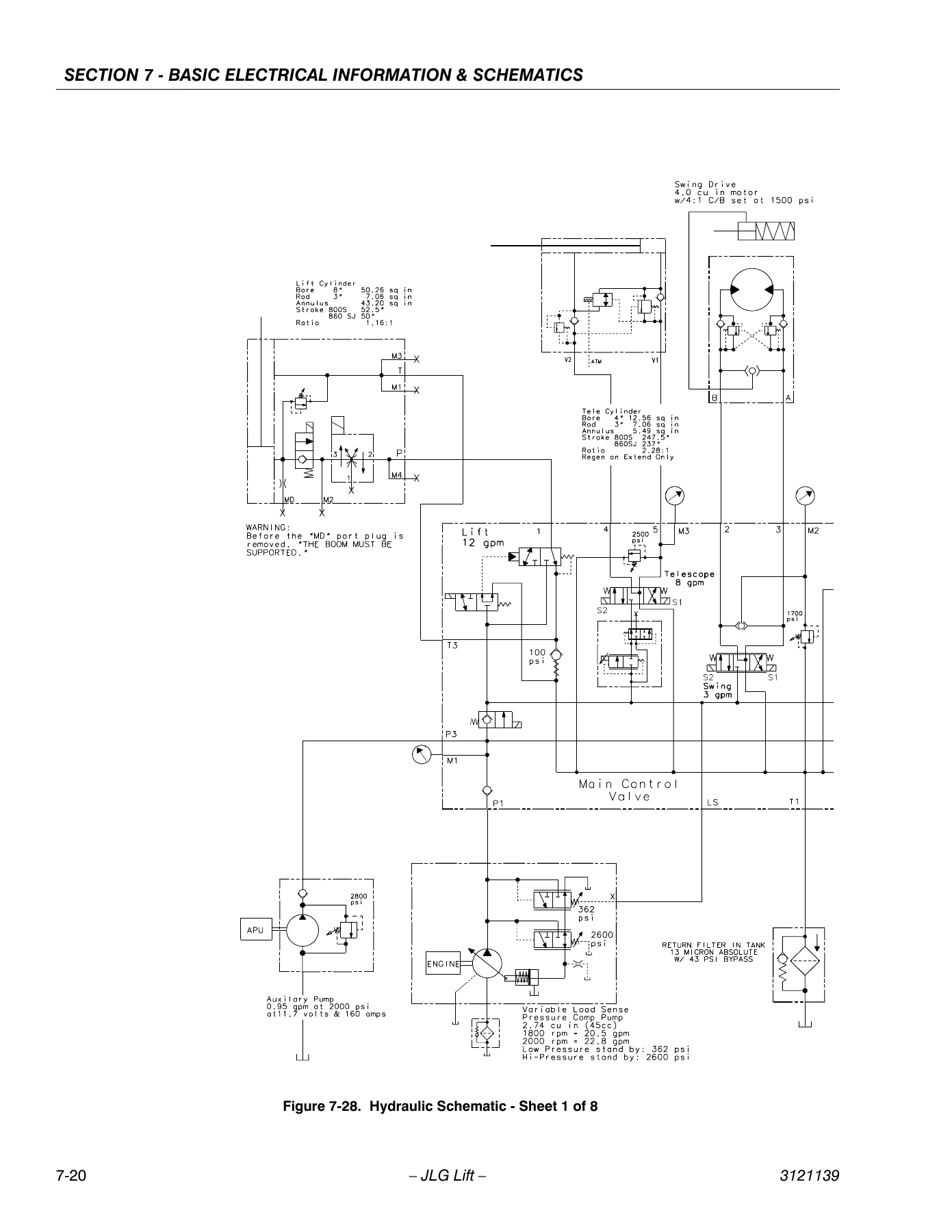
  • Section 7 – Basic Electrical Information & Schematics: Multimeter basics, silicone dielectric compound application, AMP and Deutsch connectors, electrical component installation, full electrical schematics, full hydraulic schematics

Complete PDF Bookmark Tree

Complete Bookmarks

The complete bookmarks in the “JLG 800S 860SJ Service and Maintenance Manual – 3121139 PDF” are as follows:

Section 1. Specificationsp. 17
1.1 Operating specificationsp. 17
1.2 Specifications and Performance Datap. 17
1.3 Capacitiesp. 18
1.4 Component Datap. 18
Engine Datap. 18
Batteryp. 19
1.5 Tiresp. 19
1.6 Function Speedsp. 19
Machine Orientation When Doing Speed Testsp. 19
Test Notesp. 20
1.7 Torque Requirementsp. 20
1.8 Lubricationp. 20
Hydraulic Oilp. 20
1.9 Pressure Settingsp. 21
1.10 Major Component Weightsp. 21
1.11 Operator Maintenancep. 22
Draining Oil Build Up From The Propane Regulatorp. 26
Propane Fuel Filter Replacementp. 27
Propane Fuel System Pressure Reliefp. 28
1.12 Serial Number Locationp. 28
Section 2. Generalp. 35
2.1 Machine Preparation, Inspection, and Maintenancep. 35
Generalp. 35
Preparation, Inspection, and Maintenancep. 35
Pre-Start Inspectionp. 35
Pre-Delivery Inspection and Frequent Inspectionp. 35
Annual Machine Inspectionp. 35
Preventative Maintenancep. 35
2.2 Service and Guidelinesp. 36
Generalp. 36
Safety and Workmanshipp. 36
Cleanlinessp. 36
Components Removal and Installationp. 36
Component Disassembly and Reassemblyp. 37
Pressure-Fit Partsp. 37
Bearingsp. 37
Gasketsp. 37
Bolt Usage and Torque Applicationp. 37
Hydraulic Lines and Electrical Wiringp. 37
Hydraulic Systemp. 37
Lubricationp. 37
Batteryp. 37
Lubrication and Servicingp. 37
2.3 Lubrication and Informationp. 38
Hydraulic Systemp. 38
Hydraulic Oilp. 38
Changing Hydraulic Oilp. 38
Lubrication Specificationsp. 38
2.4 Cylinder Drift Testp. 38
Platform Driftp. 38
Cylinder Driftp. 39
2.5 Pins and Composite Bearing Repair Guidelinesp. 39
2.6 Welding on JLG Equipmentp. 39
Do the Following When Welding on JLG Equipmentp. 39
Do NOT Do the Following When Welding on JLG Equipmentp. 39
Section 3. Chassis & Turntablep. 47
3.1 Tires & Wheelsp. 47
Tire Inflationp. 47
Tire Damagep. 47
Tire Replacementp. 47
Wheel Replacementp. 47
Wheel Installationp. 48
3.2 Wheel Drive Assembly, 2WDp. 48
Removal and Disassemblyp. 48
Assembly and Installationp. 49
3.3 Drive Motor – 2WD (Prior to S/N 83331)p. 50
Replacing the Drive Shaft Sealp. 50
Disassemblyp. 51
Assemblyp. 55
3.4 Drive Motor (S/N 83331 to Present)p. 57
Descriptionp. 57
Shaft Seal Replacementp. 57
Loop Flushing Valvep. 58
Troubleshootingp. 59
Disassemblyp. 60
Inspectionp. 64
Assemblyp. 66
Initial Start-up Proceduresp. 71
3.5 Torque Hubp. 72
Disassemblyp. 72
Cleaning and Inspectionp. 72
Repairp. 73
Assemblyp. 75
3.6 Wheel Drive Assembly, 4WDp. 80
Removal and Disassemblyp. 80
Assembly and Installationp. 80
3.7 Torque Hub (4WD Machines W/ Integral Brake)p. 81
Roll, Leak and Brake Testingp. 81
Tightening and Torquing Boltsp. 81
Main Disassemblyp. 82
Input Carrier Disassemblyp. 84
Output Carrier Disassemblyp. 85
Housing-Spindle Disassemblyp. 86
Spindle-Brake Disassemblyp. 87
Input Carrier Sub-Assemblyp. 88
Output Carrier Sub-Assemblyp. 90
Spindle-Brake Sub-Assemblyp. 92
Housing-Spindle Sub-Assemblyp. 94
DW2B Integral Brake Checkp. 94
Main Assemblyp. 96
3.8 Drive Brake, 2WD – Mico (Prior to S/N 83331)p. 108
Disassemblyp. 108
Assemblyp. 108
Bleedingp. 110
3.9 Re-Aligning torque hub input couplingp. 111
Equipment Requiredp. 111
Procedurep. 111
3.10 Oscillating Axle Bleeding Procedure and Lockout Testp. 111
Lockout Cylinder Bleedingp. 111
Oscillating Axle Lockout Testp. 112
3.11 Swing Drive Hubp. 113
Disassemblyp. 113
Main Assembly Procedurep. 113
Hub Shaft Sub-Assemblyp. 116
Carrier Sub-Assemblyp. 118
3.12 Swing Brake – Mico (Prior to S/N 66417)p. 121
Disassemblyp. 121
Assemblyp. 121
Bleedingp. 123
3.13 Swing Motor (Prior to S/N 66417)p. 124
Disassemblyp. 124
Inspection and Cleaningp. 126
Assemblyp. 126
Timing Procedurep. 128
3.14 Swing Motor (S/N 66417 to Present)p. 131
Disassembly and inspectionp. 131
Assemblyp. 138
One Piece Stator Constructionp. 145
3.15 Procedure For Setting Gear Backlashp. 146
3.16 Swing Bearingp. 150
Turntable Bearing Mounting Bolt Condition Checkp. 150
Wear Tolerancep. 153
Swing Bearing Removalp. 153
Swing Bearing Installationp. 156
Swing Bearing Torque Valuesp. 156
3.17 Rotary Couplingp. 157
3.18 Generatorp. 160
Every 250 hoursp. 160
Every 500 hoursp. 160
Overload Protectionp. 161
Inspecting Brushes, Replacing Brushes, and Cleaning Slip Ringsp. 161
3.19 Ford EFI Enginep. 163
Performing Diagnosticsp. 163
EFI Diagnosticsp. 163
ECM and Sensorsp. 164
Fuel Systemp. 170
3.20 Deutz EMR 2 (S/N 85332 to Present)p. 175
3.21 GM Engine General Maintenancep. 188
Maintenance of the Drive Beltp. 188
Engine Electrical System Maintenancep. 188
Checking/Filling Engine Oil Levelp. 188
Changing The Engine Oilp. 189
Coolant Fill Procedure – Dual Fuel Enginep. 189
3.22 GM Engine Dual Fuel Systemp. 190
Fuel Filterp. 191
Electric Lock Offp. 191
EPR Assemblyp. 191
Low Pressure Regulator (LPR)p. 192
Air Fuel Mixerp. 192
Electronic Throttle Control (ETC)p. 193
Engine Control Modulep. 193
Heated Exhaust Gas Oxygen Sensorp. 194
Gasoline Multi Point Fuel Injection System (MPFI)p. 194
Gasoline Fuel Pumpp. 194
Gasoline Pressure And Temperature Sensor Manifoldp. 194
Fuel Filterp. 195
Fuel Injector Railp. 195
Fuel Injectorp. 195
3.23 GM Engine Fuel System Repairp. 195
Propane Fuel System Pressure Reliefp. 195
Propane Fuel System Leak Testp. 195
Propane Fuel Filter Replacementp. 196
Electronic Pressure Regulator (EPR) Assembly Replacementp. 196
Temperature Manifold Absolute Pressure (TMAP) Sensorp. 198
Electronic Throttle Control Replacementp. 198
Mixer Replacementp. 199
Coolant Hose Replacementp. 200
Vapor Hose Replacementp. 200
Engine Control Module Replacementp. 200
Heated Exhaust Gas Oxygen Sensor Replacementp. 200
3.24 GM Engine LPG Fuel System Diagnosisp. 201
Fuel System Descriptionp. 201
Diagnostic Aidsp. 201
Section 4. Boom & Platformp. 217
4.1 Boom Maintenancep. 217
Removalp. 217
Boom Disassemblyp. 218
Inspectionp. 225
Assemblyp. 225
Installationp. 230
Telescope Cylinder/Boom Cable Removalp. 230
Telescope Cylinder/Boom Cable Installationp. 232
Lift Cylinder Removalp. 234
Lift Cylinder Installationp. 234
4.2 Wire Ropep. 235
Inspectionp. 235
Three Month Inspectionp. 235
Seven Year Inspectionp. 235
Replacement Criteriap. 235
4.3 Boom Rope Torquing Proceduresp. 236
Torque Proceduresp. 236
4.4 Elevation & Capacity Switches – 800Sp. 237
4.5 Elevation, Dual Capacity, & Transport Switch – 860SJp. 239
4.6 Electronic Platform Levelingp. 241
Descriptionp. 241
Normal Operationp. 244
Platform Leveling Faultp. 245
CAN Errorsp. 247
Replacing the Level Sensorsp. 247
Additional Platform and Jib Valvesp. 247
Platform Leveling Calibration Procedurep. 247
4.7 Powertrack Maintenancep. 249
One Piece Bracket Maintenancep. 249
Two Piece Bracket Maintenancep. 251
Snap Rings and Screwsp. 253
4.8 Helac Rotary actuatorp. 254
Theory of Operationp. 254
Tools Required for Assembly/Disassemblyp. 257
Disassemblyp. 257
Inspectionp. 261
Assemblyp. 261
Installing Counterbalance Valvep. 265
Testing the Actuatorp. 266
Installation and Bleedingp. 266
Troubleshootingp. 267
4.9 Load Sensing devicep. 268
Calibrating the Load Sensorp. 268
Section 5. Hydraulicsp. 271
5.1 Lubricating O-Rings in the Hydraulic Systemp. 271
Cup and Brushp. 271
Dip Methodp. 272
Spray Methodp. 272
Brush-on Methodp. 272
5.2 Cylinder Repairp. 273
Disassemblyp. 273
Cleaning and Inspectionp. 274
Assemblyp. 275
Steer Cylinder Seal Repair Instructionsp. 278
5.3 Pressure Setting Procedurep. 281
Set Up of the Function Pumpp. 281
Adjustments Made at the Main Valve Blockp. 282
Adjustments Made at the Platform Valve Assemblyp. 283
5.4 Start Up Proceduresp. 288
Start Up After Overhaul or Replacement of Componentsp. 288
Section 6. JLG Control Systemp. 289
6.1 Introductionp. 289
To Connect the JLG Control System Analyzerp. 291
Using the Analyzerp. 291
Changing the Access Level of the Hand Held Analyzerp. 293
Adjusting Parameters Using the Hand Held Analyzerp. 295
Machine Setupp. 296
Level Vehicle Descriptionp. 296
Machine Personality Settingsp. 305
Analyzer Diagnostics Menu Structurep. 337
Section 7. Basic Electrical information & schematicsp. 343
7.1 Generalp. 343
7.2 Multimeter Basicsp. 343
Groundingp. 343
Backprobingp. 343
Min/Maxp. 343
Polarityp. 343
Scalep. 343
Voltage Measurementp. 343
Resistance Measurementp. 344
Continuity Measurementp. 344
Current Measurementp. 345
7.3 Applying Silicone Dielectric Compound to Electrical Connectionsp. 345
7.4 AMP Connectorp. 346
Applying Silicone Dielectric Compound to AMP Connectorsp. 346
Assemblyp. 346
Disassemblyp. 348
Wedge Lockp. 348
Service – Voltage Readingp. 348
7.5 Deutsch Connectorsp. 350
DT/DTP Series Assemblyp. 350
DT/DTP Series Disassemblyp. 350
HD30/HDP20 Series Assemblyp. 351
HD30/HDP20 Series Disassemblyp. 351

Between the covers, this JLG 800S 860SJ service manual walks through every system that keeps these telescopic boom lifts running. The chassis and turntable section alone spans more than 160 pages, covering the wheel drive assembly on both 2WD and 4WD machines, the Fairfield and Mico torque hub rebuilds, drive and swing brake service, swing bearing replacement with torque sequencing, rotary coupling seal kit installation, and full step-by-step teardown of the swing drive hub and swing motor. Engine coverage is split by manufacturer and serial number, with dedicated Ford EFI diagnostics, Deutz EMR 2 fault code lookup and vehicle/engine pin identification, and complete GM dual fuel system repair covering the EPR, LPR, mixer, ETC, TMAP and HEGO sensors.

Engines and Serial Number Coverage

The engine chapters are separated so you can match the exact procedure to the machine on the bench. Ford LRG-425 gasoline and dual fuel diagnostics run through DTC tables, ECM and sensor theory (CKP, CMP, ECT, IAT, MAP, TP, HO2S), fuel metering, open/closed loop operation and electronic ignition. Deutz EMR 2 coverage (S/N 85332 to present) includes the full troubleshooting flow chart, engine-side and vehicle-side connection diagrams, engine and vehicle plug pin identification, and a five-sheet fault code table cross-referencing fault numbers, SPN and FMI codes. GM 3.0L engines get general maintenance, drive belt tensioning, oil change procedure, dual fuel component layout, coolant fill procedure specific to dual fuel engines, and full LPG fuel system diagnosis with symptom tables covering no-start, hard start, cut-out, hesitation, backfire, lack of power, poor fuel economy and rough idle.

Diagnostics, Schematics and Control System Coverage

The JLG Control System section explains how to connect the hand-held analyzer, change access levels using the 33271 password, adjust personality parameters, navigate the machine setup menu, and read the diagnostics menu structure. It also walks through the EPBCS block diagram, analyzer connecting points and control module locations. The back of the book is filled with the schematic set: six sheets of electrical schematic covering Deutz EMR2, GM and CAT variants, plus eight sheets of hydraulic schematic. Whether you need to trace a throttle actuator signal, identify a boom capacity switch, or check a platform level valve circuit, the diagrams are printed alongside the procedures that reference them.

IMAGES PREVIEW

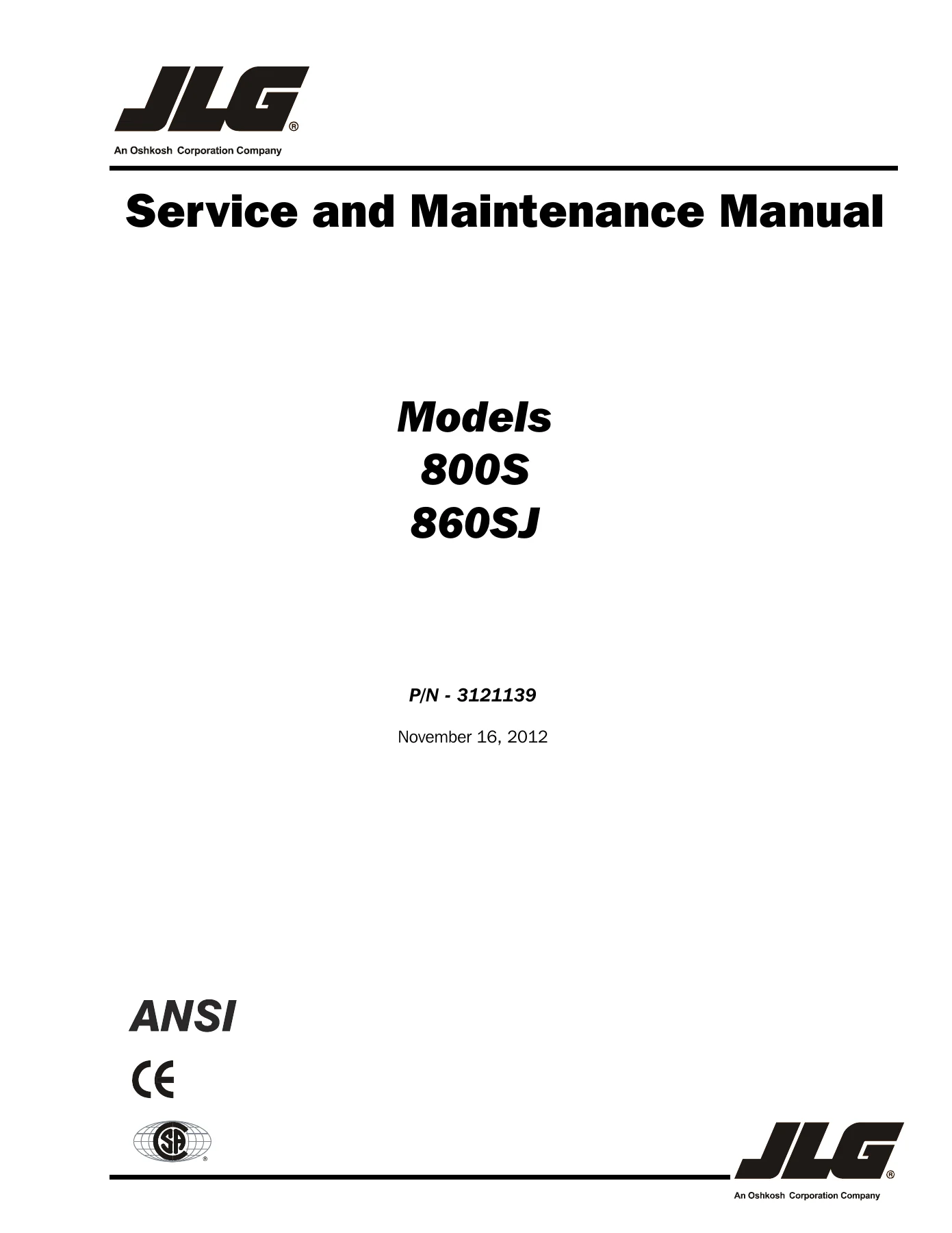
JLG 800S 860SJ Service and Maintenance Manual - 3121139 PDF — PDF page 1 preview
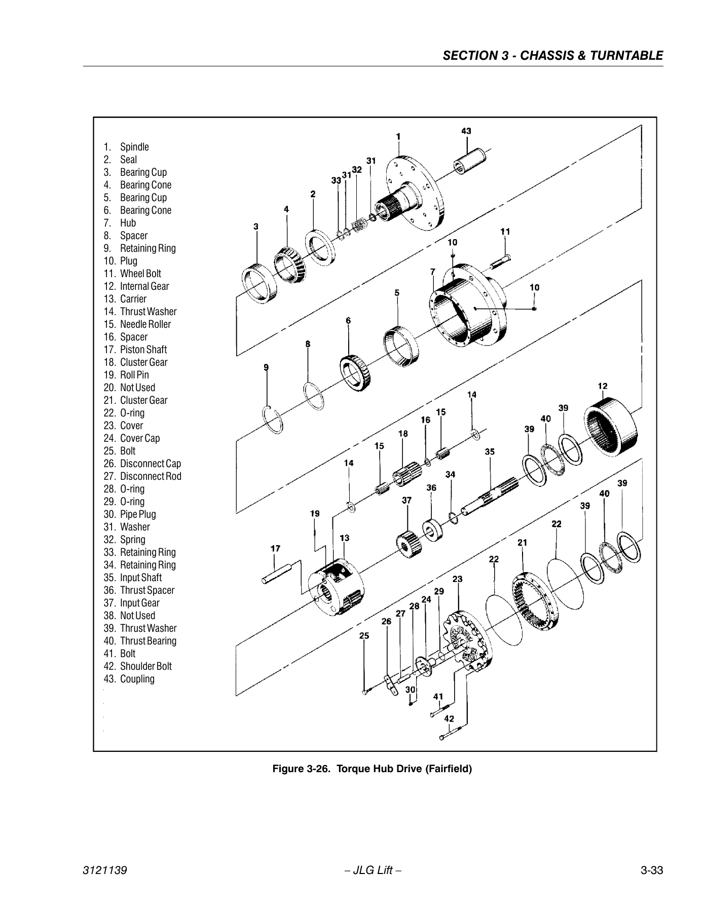
JLG 800S 860SJ Service and Maintenance Manual - 3121139 PDF — PDF page 79 preview
JLG 800S 860SJ Service and Maintenance Manual - 3121139 PDF — PDF page 362 preview

Who This Manual Is For

Independent mechanics, fleet maintenance departments, rental companies and owner-operators of JLG 800S and 860SJ lifts will all find this JLG 800S 860SJ maintenance manual directly usable. Torque values, hydraulic pressure settings, bearing tolerance limits, wire rope replacement criteria, cylinder drift limits and diagnostic fault code tables are all in one place. Because it covers multiple serial number ranges and multiple engine options, one PDF works across a whole fleet of 800S and 860SJ machines rather than just a single unit.

Get the JLG 800S 860SJ Manual Today

With this JLG 800S 860SJ service and maintenance manual at hand you can carry out scheduled maintenance, rebuild a torque hub or swing drive, replace swing bearing bolts to correct torque, set gear backlash, troubleshoot a Ford EFI or Deutz EMR 2 fault, diagnose a GM LPG fuel system complaint, trace an electrical fault from the schematic, and rebuild a hydraulic cylinder – all using the manufacturer’s own procedures and specifications instead of guesswork. Getting a torque value or pressure setting wrong on a boom lift is not a small thing; the manual is what makes sure the job is done right the first time. The file is delivered instantly as a PDF download, no shipping or waiting, and can be opened on a laptop, tablet or phone in the workshop or printed and kept in the service truck. Order the JLG 800S 860SJ Service and Maintenance Manual – 3121139 now and have the full manual in your hands in minutes.
Reviews

There are no reviews yet.

Be the first to review “JLG 800S 860SJ Service and Maintenance Manual – 3121139 PDF”

What Our Customers Say

★★★★★ Live reviews from customers
Loading customer reviews...
0
    0
    Your Cart
    Your cart is emptyReturn to Shop
    🛒
    Recently Purchased
    🕒 verified order