★ TRUSTED BY 321,897+ PROFESSIONALS WORLDWIDE
🏢
Trusted Business
Verified & Licensed
🛡️
Virus Free Files
100% Safe Downloads
🔒
Secure Payment
SSL Protected
Instant Delivery
Available Immediately
Sale!

Bobcat S650 Skid-Steer Loader Service Manual – 6990746enUS

Original price was: $34.95.Current price is: $21.95.

Complete factory service manual for the Bobcat S650 Skid-Steer Loader (Publication 6990746enUS, October 2018). Covers serial numbers ALJ811001 & Above, S1ML11001 & Above, and B2LA11001 & Above with comprehensive maintenance, full hydraulic and hydrostatic overhaul procedures, testing specs, and system schematics.

Instant PDF Download
Available immediately
💾
Save to Your Device
Download & keep forever
🛡️
Antivirus Scanned
100% virus-free
🌍
Trusted Worldwide
175,000+ customers

Description

Bobcat S650 Skid-Steer Loader Service Manual – 6990746enUS

The Bobcat S650 Skid-Steer Loader Service Manual – 6990746enUS is the complete workshop guide designed for mechanics, technicians, and equipment owners carrying out maintenance, troubleshooting, and complete system overhauls. Covering machines within serial number ranges ALJ811001 & Above, S1ML11001 & Above, and B2LA11001 & Above, this manual provides factory-grade technical data, step-by-step assembly and disassembly procedures, tightening specifications, and hydraulic schematics for standard and high-flow configurations.

File Details

  • Manual Type: Workshop Service Manual
  • Brand: Bobcat
  • Model: S650 Skid-Steer Loader
  • Applicable Serial Numbers: S/N ALJ811001 & Above, S/N S1ML11001 & Above, S/N B2LA11001 & Above
  • Publication Number: 6990746enUS (10-18) (G)
  • Publication Date: October 2018
  • Language: English
  • Page Count: 1170
  • File Format: PDF

Chapters & Sections Covered

  • Safety & Maintenance: Safe lifting and blocking procedures; lift arm support device installation and removal; operator cab (ROPS/FOPS Level I and II) raising, lowering, and hardware torquing; cab door sensor operation; Special Applications Kit and Forestry Door/Window Kit inspection and cleaning; trailer transport and tie-down locations; towing precautions; Remote Start Tool Kits (MEL1563, MEL1566 harness communicator, and 7217666 service tool kit); scheduled maintenance intervals from 10-hour checks to 1500-hour coolant replacement; dual-element air cleaner servicing; engine cooling system maintenance and radiator/cooler cleanout; propylene glycol coolant draining and refilling; fuel system requirements (Ultra Low Sulfur Diesel ASTM D975, EN590, and B5/B7 biodiesel considerations), fuel filter replacement, and system bleeding; engine lubrication requirements (API CJ-4 / ACEA E9), drain hose routing, and filter replacement; hydraulic/hydrostatic reservoir checking, fluid replacement, main canister filter, charge filter, and breather cap servicing; final drive chaincase fluid levels and draining; Bob-Tach (hand lever and Power Bob-Tach) wedge engagement and inspection; machine grease lubrication points; tire maintenance, rotation, and wheel nut torquing (217 N•m / 160 ft-lb); pivot pin inspection (48–54 N•m / 35–40 ft-lb); machine storage and return-to-service protocols; emergency exits (rear window removal via latches or rubber pull cord, front door release); and seat belt inspection.
  • Hydraulic System: Full glossary of hydraulic and hydrostatic ISO schematic symbols; complete hydraulic diagnostic troubleshooting guide; lift cylinder testing, removal, teardown, rebuild, piston nut torquing (1491 N•m / 1100 ft-lb), and gland nut assembly (373 N•m / 275 ft-lb); tilt cylinder testing, removal, pivot pin extraction, parts identification for earlier and later production, piston repacking, and nut torquing (1152 N•m / 850 ft-lb earlier, 1491 N•m / 1100 ft-lb later); Power Bob-Tach hydraulic cylinder testing, removal, and overhaul (190 N•m / 140 ft-lb piston nut torque); main relief valve testing with pressure gauge MEL1355-3, pressure adjustment (24132 kPa / 3500 psi standard; 25511–26200 kPa / 3700–3800 psi with auxiliary relief), and cartridge replacement; auxiliary relief valve adjustment (23787–24476 kPa / 3450–3550 psi); Standard Hydraulic Control Valve complete teardown, load check valves, anti-cavitation valves, port relief valves (27579 kPa / 4000 psi), spool centering blocks, detent sleeve orientation (radius vs. vertical lift pattern), centering spring assembly, auxiliary pilot solenoids, BICS lock valves, and bypass orifice; Advanced Control System (ACS) and Selectable Joystick Control (SJC) control valve configurations, actuator removal and replacement (in-machine and bench), actuator linkage pins, and calibration notices.
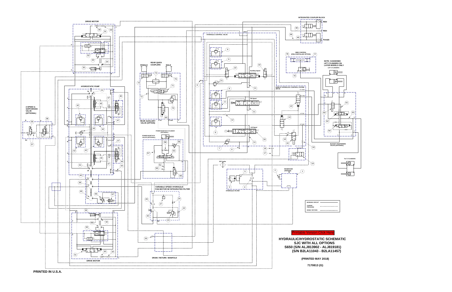
  • Hydraulic & Hydrostatic Schematics: Full-page engineering circuit schematics with detailed legends covering Manual Controls with No Options, Manual Controls with All Options (across serial breakpoints ALJ811001–ALJ813901, ALJ813902–ALJ819181, ALJ819182 & Above, B2LA11001–B2KZ11042, B2LA11043–B2LA11457, B2LA11458 & Above), SJC with No Options, and SJC with All Options (incorporating High Flow pump circuits, 2-Speed & SAPR brake valve, reversing fan motor, ride control accumulator, and bucket positioning valves).

IMAGES PREVIEW

Bobcat S650 Skid-Steer Loader Service Manual - 6990746enUS — PDF page 1 preview
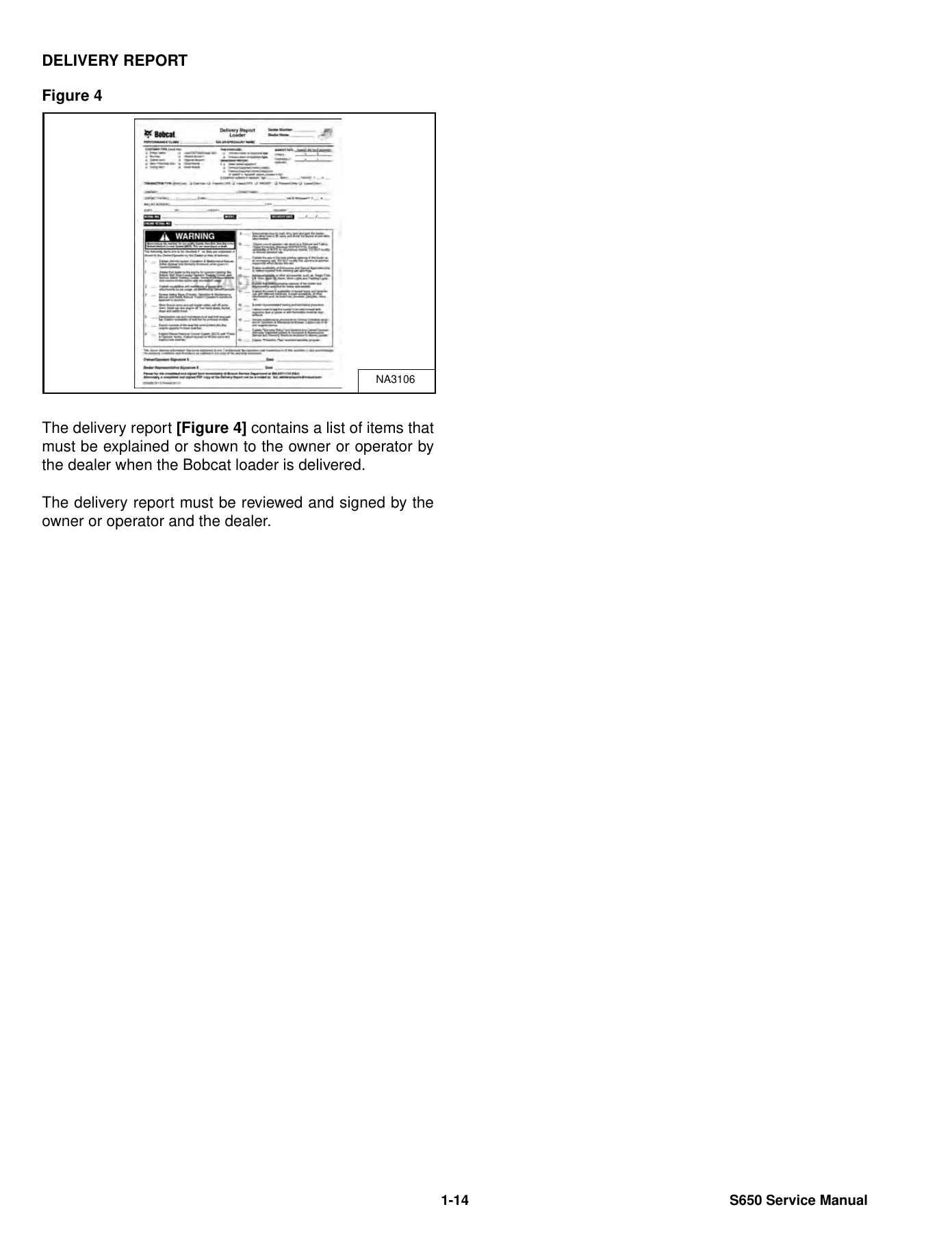
Bobcat S650 Skid-Steer Loader Service Manual - 6990746enUS — PDF page 16 preview
Bobcat S650 Skid-Steer Loader Service Manual - 6990746enUS — PDF page 124 preview

Together, these comprehensive chapters equip service personnel with exact factory disassembly sequences, component identification charts, diagnostic pathways, and factory torque limits required to perform repairs safely and accurately on the Bobcat S650 loader.

Preventative Maintenance & Machine Servicing

Routine service intervals detailed in the Bobcat S650 Skid-Steer Loader Service Manual – 6990746enUS ensure maximum uptime and operational safety. Detailed procedures guide you through every critical checkpoint, including checking fluid levels, purging air from fuel lines via the priming bulb, and properly servicing both inner and outer air cleaner elements based on instrument cluster service codes ([AIRF] and [M0117]). The manual highlights essential cooling system requirements, specifying factory-filled propylene glycol mixtures (47% water and 53% propylene glycol providing freeze protection down to -37°C / -34°F) to avoid catastrophic mixing with ethylene glycol formulations.

Technicians working on shop diagnostics benefit from complete instructions on utilizing specialized tools, including the MEL1563 Remote Start Tool and the 7217666 Service Tool Kit. These tools allow mechanics to start the machine, override traction lock systems, and operate auxiliary hydraulics safely with the operator cab raised during linkage adjustments, electrical testing, and pressure diagnostics.

Hydraulic Cylinder Rebuilding & Control Valve Overhaul

Hydraulics form the core of the S650 skid-steer loader, and this workshop manual provides deep component-level servicing details. Mechanics will find complete procedures for testing lift and tilt cylinders for internal bypass leaks before performing teardown. Step-by-step rebuilding sequences detail the use of specialized seal expanders (MEL1396-1), piston ring compressors (MEL1396-2), and gland nut spanner tools (MEL1075).

The manual provides explicit torque benchmarks, requiring 1491 N•m (1100 ft-lb) on the lift cylinder piston nut and 373 N•m (275 ft-lb) on the cylinder head. For the main hydraulic control valve, detailed cross-sectional layouts show the placement of all internal components—from the lift circuit detent mechanism to the Bobcat Interlock Control System (BICS) solenoids and lock valves. Resistance values for electronic solenoid coils (16.02–19.58 ohms for spool lock solenoids; 5.1 ohms for auxiliary proportional coils; 9.5–10.08 ohms for general coils) allow electrical faults to be pinpointed immediately.

Complete PDF Bookmark Tree

Complete Bookmarks

The complete bookmarks in the “Bobcat S650 Skid-Steer Loader Service Manual – 6990746enUS” are as follows:

MAINTENANCE SAFETYp. 3
CONTENTSp. 5
FOREWORDp. 7
FOREWORDp. 9
SAFETY INSTRUCTIONSp. 11
FIRE PREVENTIONp. 13
Maintenancep. 13
Operationp. 13
Electricalp. 13
Hydraulic Systemp. 13
Fuelingp. 13
Startingp. 13
Spark Arrester Exhaust Systemp. 13
Welding And Grindingp. 14
Fire Extinguishersp. 14
SERIAL NUMBER LOCATIONSp. 15
Loader Serial Numberp. 15
Engine Serial Numberp. 15
DELIVERY REPORTp. 16
LOADER IDENTIFICATIONp. 17
SAFETY & MAINTENANCEp. 19
LIFTING AND BLOCKING THE LOADERp. 23
Procedurep. 23
LIFT ARM SUPPORT DEVICEp. 25
Descriptionp. 25
Installingp. 26
Removingp. 27
OPERATOR CABp. 29
Descriptionp. 29
Raisingp. 30
Loweringp. 31
Cab Door Sensorp. 32
Special Applications Kitp. 33
Special Applications Kit Inspection And Maintenancep. 33
Forestry Door And Window Kitp. 34
Forestry Door And Window Kit Inspection And Maintenancep. 34
TRANSPORTING LOADER ON A TRAILERp. 35
Loading And Unloadingp. 35
Fasteningp. 35
TOWING THE LOADERp. 37
Procedurep. 37
REMOTE START TOOL KIT – MEL1563p. 39
Remote Start Tool – MEL1563p. 39
Service Tool Harness Communicator – MEL1566p. 41
Remote Start Procedurep. 41
REMOTE START TOOL (SERVICE TOOL) KIT – 7217666p. 45
Descriptionp. 45
Remote Start Tool (Service Tool) – 7022042p. 46
Loader Service Tool Harness – 6689747p. 47
Computer Service Tool Harness – 6689746p. 48
Remote Start Procedurep. 49
SERVICE SCHEDULEp. 53
Maintenance Intervalsp. 53
AIR CLEANER SERVICEp. 55
Replacing Filter Elementsp. 55
ENGINE COOLING SYSTEMp. 57
Maintenance Platformp. 57
Cleaningp. 57
Checking Levelp. 60
Removing And Replacing Coolantp. 61
FUEL SYSTEMp. 63
Fuel Specificationsp. 63
Biodiesel Blend Fuelp. 63
Filling The Fuel Tankp. 64
Fuel Filterp. 65
Removing Air From The Fuel Systemp. 66
ENGINE LUBRICATION SYSTEMp. 67
Checking And Adding Engine Oilp. 67
Engine Oil Chartp. 67
Removing And Replacing Oil And Filterp. 68
HYDRAULIC / HYDROSTATIC SYSTEMp. 71
Checking And Adding Fluidp. 71
Hydraulic / Hydrostatic Fluid Chartp. 71
Removing And Replacing Hydraulic Fluidp. 72
Hydraulic / Hydrostatic Filter Identificationp. 74
Removing And Replacing Hydraulic / Hydrostatic Filter (Earlier Models)p. 75
Removing And Replacing Hydraulic / Hydrostatic Filter (Later Models)p. 76
Removing And Replacing Hydraulic Charge Filterp. 77
Replacing Reservoir Breather Capp. 79
FINAL DRIVE TRANSMISSION (CHAINCASE)p. 81
Checking And Adding Fluidp. 81
Removing And Replacing Fluidp. 81
BOB-TACH (HAND LEVER)p. 83
Inspection And Maintenancep. 83
BOB-TACH (POWER)p. 85
Inspection And Maintenancep. 85
LUBRICATING THE LOADERp. 87
Lubrication Locationsp. 87
TIRE MAINTENANCEp. 91
Wheel Nutsp. 91
Rotatingp. 91
Mountingp. 92
PIVOT PINSp. 93
Inspection And Maintenancep. 93
LOADER STORAGE AND RETURN TO SERVICEp. 95
Storagep. 95
Return To Servicep. 95
STOPPING THE ENGINE AND LEAVING THE LOADERp. 97
Procedurep. 97
EMERGENCY EXITp. 99
Rear Window Identificationp. 99
Rear Window Removal (Latches)p. 99
Rear Window Removal (Rubber Cord)p. 99
External Access (Rear Window With Latches)p. 100
External Access (Rear Window With Rubber Cord)p. 100
Front Doorp. 100
SEAT BELTp. 103
Inspection And Maintenancep. 103
HYDRAULIC SYSTEMp. 105
HYDRAULIC / HYDROSTATIC SCHEMATICSp. 111
HYDRAULIC SYSTEM INFORMATIONp. 127
Glossary Of Hydraulic / Hydrostatic Symbolsp. 127
Troubleshootingp. 131
CYLINDER (LIFT)p. 133
Testingp. 133
Removal And Installationp. 134
Parts Identificationp. 138
Disassemblyp. 139
Assemblyp. 140
CYLINDER (TILT)p. 143
Testingp. 143
Removal And Installationp. 144
Base End Pivot Pin Removal And Installationp. 145
Parts Identification (Earlier Models)p. 146
Parts Identification (Later Models)p. 147
Disassemblyp. 148
Assemblyp. 150
CYLINDER (BOB-TACH)p. 153
Testingp. 153
Removal And Installationp. 154
Parts Identificationp. 155
Disassemblyp. 156
Assemblyp. 157
MAIN RELIEF VALVEp. 161
Descriptionp. 161
Testingp. 162
Main Relief Valve Adjustmentp. 164
Main Relief Valve Removal And Installationp. 164
Auxiliary Relief Valve Adjustmentp. 165
Auxiliary Relief Valve Removal And Installationp. 166
HYDRAULIC CONTROL VALVE (STANDARD)p. 167
Descriptionp. 167
Removal And Installationp. 168
Mount Bracket Removal And Installationp. 172
Identification Chartp. 173
Lift Load Check Valve Removal And Installationp. 174
Load Check Valve Removal And Installation (Tilt And Auxiliary)p. 175
Anti-Cavitation Valve Removal And Installation (Lift, Rod End)p. 176
Port Relief / Anti-Cavitation Valve Removal And Installation (Lift, Base End)p. 176
Port Relief / Anti-Cavitation Valve Removal And Installation (Tilt, Base End)p. 177
Port Relief / Anti-Cavitation Valve Removal And Installation (Tilt, Rod End)p. 177
Port Relief Valve Removal And Installationp. 178
Plug Removal And Installationp. 180
Rubber Boot Removal And Installationp. 181
End Cap Block Removal And Installationp. 181
Lift Spool And Detent Removal And Installationp. 182
Tilt Spool Removal And Installationp. 190
Auxiliary Spool Removal And Installationp. 192
Auxiliary Solenoid Removal And Installationp. 193
Solenoid Removal And Installationp. 194
Lock Valve Removal And Installationp. 195
Lift Arm Bypass Orifice Removal And Installationp. 197
Main Relief Valve Removal And Installationp. 197
Auxiliary Relief Valve Removal And Installationp. 198
Check Valve Removal And Installationp. 198
HYDRAULIC CONTROL VALVE (ACS) OR (SJC)p. 201
Descriptionp. 201
Removal And Installationp. 201
Actuator Removal And Installation (In Loader)p. 206
Actuator Removal And Installation (Out Of Loader)p. 207
Identification Chartp. 210
Mount Bracket Removal And Installationp. 211
Lift Load Check Valve Removal And Installationp. 211
Load Check Valve Removal And Installation (Tilt And Auxiliary)p. 212
Anti-Cavitation Valve Removal And Installation (Lift, Rod End)p. 213
Port Relief / Anti-Cavitation Valve Removal And Installation (Lift, Base End)p. 213
Port Relief / Anti-Cavitation Valve Removal And Installation (Tilt, Base End)p. 214
Port Relief / Anti-Cavitation Valve Removal And Installation (Tilt, Rod End)p. 214
Port Relief Valve Removal And Installationp. 215
Plug Removal And Installationp. 217
End Cap Block Removal And Installationp. 218
Lift Spool Removal And Installationp. 218
Lift Spool Disassembly And Assemblyp. 220
Tilt Spool Removal And Installationp. 221
Tilt Spool Disassembly And Assemblyp. 222
Auxiliary Spool Removal And Installationp. 223
Auxiliary Solenoid Removal And Installationp. 224
Solenoid Removal And Installationp. 225
Lock Valve Removal And Installationp. 226
Lift Arm Bypass Orifice Removal And Installationp. 228
Main Relief Valve Removal And Installationp. 228
Auxiliary Relief Valve Removal And Installationp. 229
Check Valve Removal And Installationp. 229
LIFT ARM BYPASS CONTROL VALVEp. 231
Descriptionp. 231
Removal And Installationp. 232
Bracket Removal And Installationp. 233
Disassembly And Assemblyp. 233
HYDRAULIC PUMPp. 235
Descriptionp. 235
Pump Test At Quick Couplersp. 235
Direct Pump Test (Standard Section)p. 236
Direct Pump Test (Charge Section)p. 238
Removal And Installationp. 240
Hydraulic Pump Startupp. 242
Parts Identificationp. 243
Disassembly And Assemblyp. 244
HYDRAULIC PUMP (HIGH FLOW)p. 245
Descriptionp. 245
Pump Test At Quick Couplersp. 245
Direct Pump Test (Standard Section)p. 246
Direct Pump Test (Charge Section)p. 247
Direct Pump Test (High Flow Section)p. 249
High Flow Relief Valve Adjustmentp. 251
High Flow Relief Valve Removal And Installationp. 252
Solenoid Removal And Installationp. 253
Removal And Installationp. 254
Hydraulic Pump Startupp. 256
Parts Identificationp. 257
Disassembly And Assemblyp. 258
HYDRAULIC / HYDROSTATIC FILTERS (EARLIER MODELS)p. 259
Descriptionp. 259
Housing Removal And Installationp. 259
HYDRAULIC / HYDROSTATIC FILTERS (LATER MODELS)p. 261
Descriptionp. 261
Housing Removal And Installationp. 261
HYDRAULIC FLUID RESERVOIRp. 263
Descriptionp. 263
Removal And Installationp. 263
Hydraulic Fluid Screenp. 264
OIL COOLERp. 265
Descriptionp. 265
Removal And Installationp. 265
BUCKET POSITION VALVEp. 267
Descriptionp. 267
Solenoid Removal And Installationp. 267
Solenoid Testingp. 269
Removal And Installationp. 269
Disassembly And Assemblyp. 272
REAR AUXILIARY DIVERTER VALVEp. 273
Descriptionp. 273
Solenoid Testingp. 273
Removal And Installationp. 274
Disassembly And Assemblyp. 276
BOB-TACH (POWER) BLOCK (S/N ALJ811001 – ALJ813901)p. 283
Descriptionp. 283
Removal And Installationp. 283
Disassembly And Assemblyp. 285
BOB-TACH (POWER) BLOCK (S/N ALJ813902 & ABOVE)p. 293
Descriptionp. 293
Testing Relief Valvep. 294
Removal And Installationp. 296
Disassembly And Assemblyp. 298
FRONT AUXILIARY HYDRAULIC COUPLER BLOCKp. 303
Descriptionp. 303
Removal And Installationp. 304
Disassembly And Assembly (FFI/FI)p. 304
Disassembly And Assembly (FFH/FH)p. 306
AUTOMATIC RIDE CONTROLp. 309
Descriptionp. 309
Removal And Installationp. 310
Checking The Pressure In The Accumulatorp. 313
Adding Nitrogen To The Accumulatorp. 315
HYDROSTATIC SYSTEMp. 317
HYDROSTATIC SYSTEM INFORMATIONp. 319
Troubleshootingp. 319
Descriptionp. 320
HYDROSTATIC DRIVE MOTORp. 321
Descriptionp. 321
Removal And Installationp. 322
Parts Identificationp. 324
Disassembly And Assemblyp. 325
HYDROSTATIC DRIVE MOTOR (TWO-SPEED)p. 329
Descriptionp. 329
Removal And Installationp. 329
Parts Identificationp. 332
Disassemblyp. 333
Assemblyp. 339
HYDROSTATIC MOTOR CARRIERp. 345
Descriptionp. 345
Removal And Installationp. 346
Parts Identificationp. 347
Disassemblyp. 348
Assemblyp. 350
HYDROSTATIC MOTOR CARRIER (SJC)p. 353
Descriptionp. 353
Removal And Installationp. 354
Parts Identificationp. 356
Disassemblyp. 356
Assemblyp. 359
CHARGE PRESSUREp. 361
Descriptionp. 361
Testingp. 361
Sender Removal And Installation (Earlier Models)p. 363
Sender Removal And Installation (Later Models)p. 363
Adjustingp. 364
HYDROSTATIC PUMPp. 367
Descriptionp. 367
Removal And Installationp. 368
Hydrostatic Pump Startupp. 369
Replenishing / High Pressure Relief Valve Removal And Installationp. 369
Parts Identification (Left Half)p. 370
Parts Identification (Right Half)p. 371
Disassemblyp. 372
Assemblyp. 379
HYDROSTATIC PUMP (SJC)p. 387
Descriptionp. 387
Hydraulic Controller Removal And Installationp. 388
Removal And Installationp. 390
Hydrostatic Pump Startupp. 391
Parts Identificationp. 392
High Pressure Relief And Bypass Valvep. 393
Charge Relief Valvep. 394
Disassembly And Assemblyp. 395
Mechanical Neutral Adjustmentp. 408
Hydraulic Controller Neutral Adjustmentp. 411
DRIVE BELTp. 415
Belt Adjustmentp. 415
Stop Adjustmentp. 415
Belt Replacementp. 416
Tensioner Pulley Removal And Installation (Earlier Models)p. 418
Tensioner Pulley Disassembly And Assemblyp. 418
Tensioner Pulley Removal And Installation (Later Models)p. 419
Tensioner Pulley Disassembly And Assemblyp. 419
TWO-SPEED / BRAKE VALVEp. 421
Descriptionp. 421
Valve Block Removal And Installationp. 422
Valve Block Disassembly And Assemblyp. 424
DRAIN MANIFOLDp. 427
Descriptionp. 427
Drain Manifold Removal And Installationp. 427
DRIVE SYSTEMp. 429
BRAKE (SINGLE SPEED)p. 431
Descriptionp. 431
Disc Removal And Installationp. 431
BRAKE (TWO-SPEED)p. 433
Descriptionp. 433
DRIVE COMPONENTSp. 435
Descriptionp. 435
Axle Seal Removal And Installationp. 436
Axle, Sprocket And Bearings Removal And Installationp. 438
Chain Removal And Installationp. 441
CHAINCASEp. 443
Descriptionp. 443
Front Cover Removal And Installationp. 443
Center Cover Removal And Installationp. 444
Rear Cover Removal And Installationp. 445
MAINFRAMEp. 447
SEAT BARp. 451
Descriptionp. 451
Removal And Installationp. 451
Disassembly And Assemblyp. 452
Compression Spring Disassembly And Assemblyp. 453
OPERATOR CABp. 455
Gas Spring Removal And Installationp. 455
Gas Spring Bracket Disassembly And Assemblyp. 456
Removal And Installationp. 457
OPERATOR SEATp. 459
Removal And Installationp. 459
Seat Belt Removal And Installation (Retractable)p. 459
Seat Belt And Bracket Removal And Installation (Standard)p. 459
Seat Belt Bracket Removal And Installationp. 459
OPERATOR SEAT (SUSPENSION)p. 461
Removal And Installationp. 461
Slide Rail Removal And Installationp. 461
Seat Belt Removal And Installationp. 462
Lower Cushion Removalp. 462
Lower Cushion Installationp. 463
Back Cushion Removal And Installationp. 463
Shock Removal And Installationp. 464
3-Point Seat Belt Removal And Installationp. 464
BOB-TACH (HAND LEVER)p. 467
Descriptionp. 467
Removal And Installationp. 467
Lever And Wedge Disassembly And Assemblyp. 469
Pivot Pin Bushing And Seal Removal And Installationp. 472
BOB-TACH (POWER)p. 473
Descriptionp. 473
Removal And Installationp. 473
Lever And Wedge Disassembly And Assemblyp. 476
Pivot Pin Bushing And Seal Removal And Installationp. 478
LIFT ARMSp. 479
Stabilizer Bar Removal And Installationp. 479
Link Removal And Installationp. 480
Removal And Installationp. 481
REAR GRILLEp. 485
Removingp. 485
Installingp. 486
Shield Removal And Installationp. 487
REAR DOOR (TAILGATE)p. 489
Removal And Installationp. 489
Striker Removal And Installationp. 490
Striker Disassembly And Assemblyp. 490
Striker (Adjusting)p. 490
Latch Removal And Installationp. 491
FUEL TANKp. 493
Removal And Installationp. 493
Fuel Level Sender Removal And Installationp. 495
Fuel Fill Screen Removal And Installationp. 495
CONTROL PEDALS AND LINKAGESp. 497
Descriptionp. 497
Pedal Removal And Installationp. 497
Linkage Removal And Installationp. 498
Pedal (Adjusting)p. 499
Floor Pan Removal And Installationp. 500
CONTROL PEDALS AND LINKAGES (ACS)p. 501
Descriptionp. 501
Pedal Removal And Installationp. 501
Linkage Removal And Installationp. 502
Pedal (Adjusting)p. 502
Floor Pan Removal And Installationp. 503
CONTROL PANELp. 505
Descriptionp. 505
Removal And Installationp. 506
Disassembly And Assemblyp. 508
Linkage Removal And Installationp. 512
Pintle Arm Disassembly And Assemblyp. 515
Linkage Neutral (Adjusting)p. 516
Linkage Travel (Adjusting)p. 520
Shock Removal And Installationp. 524
CONTROL PANEL (SJC)p. 525
Descriptionp. 525
Removal And Installationp. 525
CONTROL HANDLE / LEVERp. 527
Descriptionp. 527
Lever Removal And Installationp. 527
Boot Removal And Installationp. 527
CONTROL HANDLE / LEVER (ACS)p. 529
Descriptionp. 529
Handle Sensor Removal And Installationp. 529
Handle Removal And Installationp. 532
Handle Disassembly And Assemblyp. 533
Lever Removal And Installationp. 533
Boot Removal And Installationp. 534
CONTROL HANDLE / LEVER (SJC)p. 535
Descriptionp. 535
Joystick Testingp. 535
Joystick Removal And Installationp. 536
ACCESS PANEL (INSIDE)p. 537
Removal And Installation (Left)p. 537
Removal And Installation (Right)p. 537
ACCESS PANEL (INSIDE) (SJC)p. 539
Removal And Installation (Left)p. 539
Removal And Installation (Right)p. 539
WINDOW (REAR)p. 541
Rear Window Identificationp. 541
Removal And Installation (Latches)p. 541
Disassembly And Assembly (Latches)p. 542
Removal (Rubber Cord)p. 543
Installation (Rubber Cord)p. 544
WINDOW (TOP)p. 547
Removal And Installationp. 547
WINDOW (SIDE)p. 549
Removal And Installationp. 549
CAB DOORp. 551
Descriptionp. 551
Removal And Installationp. 551
Disassembly And Assemblyp. 552
Aligningp. 553
Adjustingp. 554
Checking Operationp. 554
ARMRESTp. 555
Descriptionp. 555
Removal And Installationp. 555
Disassembly And Assemblyp. 556
LEFT SIDE LOWER PANELp. 559
Removal And Installationp. 559
Disassembly And Assemblyp. 562
RIGHT SIDE LOWER PANELp. 563
Removal And Installationp. 563
Disassembly And Assemblyp. 565
HEADLINERp. 567
Removal And Installationp. 567
FAN DUCT PANELSp. 569
Removal And Installationp. 569
ELECTRICAL SYSTEMp. 571
ELECTRICAL SCHEMATICSp. 577
ELECTRICAL SYSTEM INFORMATIONp. 749
Glossary Of Electrical Symbolsp. 749
Standard Cab Harness Connectorsp. 752
Deluxe Cab Harness Connectorsp. 753
Mainframe Harness Connectors – Manual Controlsp. 754
Mainframe Harness Connectors – SJCp. 755
Engine Harness Connectorsp. 756
Descriptionp. 757
Troubleshootingp. 758
Fuse And Relay Location / Identificationp. 759
Solenoid Testingp. 764
BATTERYp. 765
Removal And Installationp. 765
Servicingp. 766
Maintaining Battery Charge Levelp. 766
Battery Service During Machine Storagep. 766
Battery Testingp. 767
Battery Chargingp. 767
Using A Booster Battery (Jump Starting)p. 768
ALTERNATORp. 769
Belt Adjustmentp. 769
Belt Replacementp. 769
Charging System Inspectionp. 770
Alternator Voltage Testingp. 771
Low Voltage Testingp. 771
High Voltage Testingp. 772
Removal And Installationp. 773
Parts Identificationp. 775
STARTERp. 777
Testingp. 777
Removal And Installationp. 777
Parts Identificationp. 778
INSTRUMENT PANEL IDENTIFICATIONp. 779
Left Panelp. 779
Display Screenp. 781
Right Panel (Standard Key Panel)p. 782
Right Panel (Keyless Start Panel)p. 783
Right Panel (Deluxe Instrumentation Panel)p. 784
Left Switch Panelp. 786
Right Switch Panelp. 786
Left Side Lower Panelp. 787
Right Side Lower Panelp. 787
Left Panel Removal And Installationp. 788
Right Panel (Standard Key Panel) Removal And Installationp. 788
Right Panel (Keyless Start Panel) Removal And Installationp. 789
Right Panel (Deluxe Instrumentation Panel) Removal And Installationp. 789
Key Switch Disassembly And Assemblyp. 790
Alarm Disassembly And Assemblyp. 790
Left Switch Panel Removal And Installationp. 790
Right Switch Panel Removal And Installationp. 791
LIGHTSp. 793
Front Removal And Installationp. 793
Rear Removal And Installationp. 794
Cab Light Removal And Installation (Earlier Models)p. 794
Cab Light Removal And Installation (Later Models)p. 795
BOBCAT CONTROLLERS (GATEWAY AND AUXILIARY)p. 797
Descriptionp. 797
Connector Identificationp. 798
Removal And Installationp. 804
BOBCAT CONTROLLER (ACS)p. 805
Descriptionp. 805
Connector And Wire Identificationp. 806
Removal And Installationp. 807
BOBCAT CONTROLLER (SJC) (DRIVE)p. 809
Descriptionp. 809
Connector Identificationp. 810
Removal And Installationp. 812
ENGINE CONTROL UNIT (ECU)p. 813
Descriptionp. 813
Cleaningp. 814
Removal And Installationp. 815
DIAGNOSTIC SERVICE CODESp. 817
Viewing Service Codesp. 817
Service Codes Listp. 818
BOBCAT INTERLOCK CONTROL SYSTEM (BICS™)p. 827
Descriptionp. 827
Inspecting The BICS™ (Engine STOPPED – Key ON)p. 828
Inspecting Deactivation Of The Auxiliary Hydraulics System (Engine STOPPED – Key ON)p. 828
Inspecting The Seat Bar Sensor (Engine RUNNING)p. 828
Inspecting The Traction Lock And Parking Brake (Engine RUNNING)p. 828
Inspecting The Lift Arm Bypass Controlp. 828
Inspecting Deactivation Of Lift And Tilt Functions (ACS And SJC)p. 828
Troubleshootingp. 829
SEAT BAR SENSORp. 831
Descriptionp. 831
Troubleshootingp. 831
Testingp. 832
Removal And Installationp. 833
Bobcat Interlock Control System (BICS™) Circuit Testp. 836
TRACTION LOCKp. 839
Descriptionp. 839
Troubleshootingp. 840
Inspectingp. 841
CONTROL SYSTEM (ACS)p. 843
Descriptionp. 843
Troubleshootingp. 843
Handle Sensor Connector Disassembly And Assemblyp. 844
Switch Handle Removalp. 845
Switch Handle Installationp. 848
Actuator Connector Disassembly And Assemblyp. 850
Handle Lock Solenoid Removal And Installationp. 851
Handle Lock Solenoid Disassembly And Assemblyp. 851
Foot Sensor Removal And Installationp. 852
Foot Sensor Disassembly And Assemblyp. 853
Foot Sensor Lock Solenoid Removal And Installationp. 853
ELECTRICAL / HYDRAULIC CONTROLSp. 855
Identification Chartp. 855
Descriptionp. 856
Identification Chart ACD Group 0p. 857
Identification Chart ACD Group 1p. 858
Identification Chart ACD Group 2p. 859
Identification Chart ACD Group 3p. 860
ELECTRICAL / HYDRAULIC CONTROLS (ACS)p. 861
Identification Chartp. 861
Descriptionp. 862
Identification Chart ACD Group 0p. 863
Identification Chart ACD Group 1p. 864
Identification Chart ACD Group 2p. 865
Identification Chart ACD Group 3p. 866
ELECTRICAL / HYDRAULIC CONTROLS (SJC)p. 867
Identification Chartp. 867
Descriptionp. 868
Identification Chart ACD Group 0p. 869
Identification Chart ACD Group 1p. 870
Identification Chart ACD Group 2p. 871
Identification Chart ACD Group 3p. 872
SERVICE PC (LAPTOP COMPUTER)p. 873
Connecting Remote Start Toolp. 873
Connecting Remote Start Tool (Service Tool)p. 873
CALIBRATIONp. 875
Descriptionp. 875
Actuator Testingp. 875
Lift And Tilt Calibration (SJC)p. 877
Hydrostatic Pump Calibration (SJC)p. 879
Lift And Tilt Calibration (ACS)p. 884
STEERING DRIFT COMPENSATION (OPERATOR MODE)p. 887
Descriptionp. 887
Operationp. 887
STEERING DRIFT COMPENSATION (SERVICE MODE)p. 889
Descriptionp. 889
Operationp. 889
CONTROL PANEL SETUPp. 891
Right Panel Setup (Deluxe Instrumentation Panel)p. 891
PASSWORD SETUP (DELUXE INSTRUMENTATION PANEL)p. 895
Password Descriptionp. 895
Changing The Owner Passwordp. 895
Changing The User Passwordsp. 896
Password Lockout Featurep. 896
PASSWORD SETUP (KEYLESS START PANEL)p. 897
Password Descriptionp. 897
Changing The Owner Passwordp. 897
Password Lockout Featurep. 897
MAINTENANCE CLOCKp. 899
Descriptionp. 899
Setupp. 900
Resetp. 903
BACK-UP ALARM SYSTEMp. 905
Descriptionp. 905
Inspectingp. 905
Adjusting Switch Positionp. 906
Troubleshooting (Standard And ACS)p. 907
Troubleshooting (Joystick)p. 908
Alarm Removal And Installationp. 909
Switch Removal And Installationp. 909
FRONT HORNp. 911
Removal And Installationp. 911
Troubleshootingp. 912
Troubleshooting (Joystick)p. 913
ENGINE SPEED CONTROL (HAND)p. 915
Removal And Installationp. 915
ENGINE SPEED CONTROL (FOOT)p. 917
Removal And Installationp. 917
Disassembly And Assemblyp. 918
Foot Throttle Calibrationp. 920
CAMSHAFT AND CRANKSHAFT POSITION SENSORp. 923
Removal And Installationp. 923
TELEMATICSp. 925
Descriptionp. 925
Removal And Installationp. 925
Procedurep. 926
ENGINE SERVICEp. 927
ENGINE INFORMATIONp. 931
Descriptionp. 931
Specificationsp. 932
Sensor Locationp. 934
Torque Valuesp. 940
Troubleshootingp. 942
Engine Removal And Installationp. 944
Engine Mount Replacementp. 953
Compression – Testingp. 955
Injector Signal – Testingp. 957
Injector Signal – Testing (In-Line)p. 959
Oil Pressure Testing (At Oil Sensor On Block)p. 961
Oil Pressure Testing (At Turbocharger Oil Inlet)p. 963
DIESEL OXIDATION CATALYST (DOC)p. 965
Removal And Installationp. 965
AIR CLEANERp. 967
Housing Removal And Installationp. 967
ENGINE COOLING SYSTEM (EARLIER MODELS)p. 969
Radiator / Oil Cooler Removal And Installationp. 969
Hydraulic Fan Descriptionp. 972
Fan Duct Removal And Installationp. 972
Hydraulic Fan Motor Assembly Removal And Installationp. 973
Hydraulic Fan Motor Removal And Installationp. 974
Hydraulic Fan Motor Disassembly And Assemblyp. 975
Blower Housing Removal And Installationp. 977
Water Pump Removal And Installationp. 978
Thermostat Housing Removal And Installationp. 979
Thermostat-Testingp. 980
ENGINE COOLING SYSTEM (LATER MODELS)p. 981
Radiator / Oil Cooler Removal And Installationp. 981
Hydraulic Fan Descriptionp. 984
Reversible Hydraulic Fan Descriptionp. 984
Fan Duct Removal And Installationp. 984
Hydraulic Fan Motor Assembly Removal And Installationp. 985
Hydraulic Fan Motor Removal And Installationp. 986
Hydraulic Fan Motor Disassembly And Assemblyp. 988
Blower Housing Removal And Installationp. 996
Water Pump Removal And Installationp. 997
Thermostat Housing Removal And Installationp. 998
Thermostat-Testingp. 999
LUBRICATION SYSTEMp. 1001
Descriptionp. 1001
Oil Pan Removal And Installationp. 1002
Oil Pump Removal And Installationp. 1003
Oil Pump Relief Valve Descriptionp. 1003
Oil Pump Relief Valve Removal And Installationp. 1003
Oil Cooler Removal And Installationp. 1004
Oil Filter Head Removal And Installationp. 1004
Oil Cooler Bypass Descriptionp. 1005
Oil Cooler Bypass Removal And Installationp. 1005
FUEL SYSTEMp. 1007
Descriptionp. 1007
Transfer Pump / High Pressure Pump Removal And Installationp. 1008
Fuel Temperature Sensor Removal And Installationp. 1010
Fuel Cooler Removal And Installationp. 1011
Fuel Bypass Valve Removal And Installationp. 1011
Fuel Recirculation Valve Removal And Installationp. 1012
Fuel Rail Assembly Removal And Installationp. 1013
Fuel Injector Removal And Installationp. 1014
Injector Codingp. 1016
Removing Air From The Fuel Systemp. 1018
CYLINDER HEADp. 1021
Glow Plugs Testingp. 1021
Glow Plug Removal And Installationp. 1022
Valve Clearance Adjustmentp. 1023
Cylinder Head Removal And Installationp. 1025
Cylinder Head Disassembly And Assemblyp. 1029
Cylinder Head Inspectionp. 1030
Cylinder Head Top Clearancep. 1031
Valve Step Heightp. 1032
Valve Stem Heightp. 1032
Valve Guidep. 1033
Valvep. 1033
Valve Springp. 1034
Rocker Arm Shaft Disassembly And Assemblyp. 1035
Rocker Arm Shaft Inspectionp. 1036
Push Rod Inspectionp. 1036
CRANKSHAFT AND PISTONSp. 1037
Piston And Connecting Rod Removal And Installationp. 1037
Piston And Connecting Rod Inspectionp. 1038
Crankshaft Removal And Installationp. 1040
Cylinder Block Inspectionp. 1043
Crankshaft Inspectionp. 1045
Connecting Rod Inspectionp. 1045
Engine Component Classp. 1046
CAMSHAFTp. 1049
Removal And Installationp. 1049
Inspectingp. 1050
GEARCASEp. 1053
Gearcase Cover Removal And Installationp. 1053
Gear Backlashp. 1054
Gear Timingp. 1055
Idle Gear Removal And Installationp. 1056
Idle Gear Inspectionp. 1056
TURBOCHARGERp. 1057
Descriptionp. 1057
Removal And Installationp. 1057
Inspectionp. 1060
FLYWHEEL AND HOUSINGp. 1061
Flywheel Removal And Installationp. 1061
Ring Gear Removal And Installationp. 1062
Housing Removal And Installationp. 1062
EXHAUST GAS RECIRCULATION (EGR) SYSTEMp. 1063
Descriptionp. 1063
Removal And Installationp. 1064
Disassembly And Assemblyp. 1068
HEATING, VENTILATION AND AIR CONDITIONING (HVAC)p. 1071
AIR CONDITIONING SYSTEM FLOWp. 1073
Descriptionp. 1073
Chartp. 1074
Componentsp. 1075
Safety Equipmentp. 1078
REGULAR MAINTENANCEp. 1079
Filtersp. 1079
Belt Adjustmentp. 1080
Belt Replacementp. 1080
Condenserp. 1080
Air Conditioning Lubricationp. 1080
Air Conditioning Service Chartp. 1081
Evaporator / Heater Coilp. 1082
TROUBLESHOOTINGp. 1083
Blower Motor Does Not Operatep. 1083
Blower Motor Operates Normally, But Air Flow Is Insufficientp. 1083
Insufficient Cooling Although Air Flow And Compressor Operation Are Normalp. 1083
The Compressor Does Not Operate At All, Or Operates Improperlyp. 1083
Gauge Pressure Related Troubleshootingp. 1084
Troubleshooting Treep. 1086
Temperature / Pressure Chartp. 1090
Poor A/C Performancep. 1092
HVAC Repair And Leaksp. 1093
Electrical Systemp. 1094
Engine Coolant Bypassing The Heater Valvep. 1100
Heater Valve Not Opening Or Closingp. 1101
SYSTEM CHARGING AND RECLAMATIONp. 1103
Refrigerant Identificationp. 1103
Reclamation And Charging With Recovery / Charging Unitp. 1104
COMPRESSORp. 1107
Removal And Installationp. 1107
Oilp. 1108
Oil Checkp. 1109
CONDENSERp. 1111
Removal And Installationp. 1111
RECEIVER / DRIERp. 1113
Receiver / Drier Removal And Installationp. 1113
Pressure Switch Removal And Installationp. 1114
Schrader® Valve Removal And Installationp. 1114
EVAPORATOR / HEATER UNITp. 1115
Removal And Installationp. 1115
THERMOSTATp. 1117
Descriptionp. 1117
Removal And Installationp. 1118
EXPANSION VALVEp. 1119
Removal And Installationp. 1119
EVAPORATOR COILp. 1121
Removal And Installationp. 1121
HEATER COILp. 1123
Removal And Installationp. 1123
BLOWER FANp. 1125
Removal And Installationp. 1125
Disassembly And Assemblyp. 1126
HEATER VALVEp. 1129
Removal And Installationp. 1129
EVAPORATOR / HEATER COVERp. 1131
Removingp. 1131
Installingp. 1131
SPECIFICATIONSp. 1133
(S650) LOADER SPECIFICATIONSp. 1135
Machine Dimensionsp. 1135
Performancep. 1136
Enginep. 1136
Drive Systemp. 1137
Controlsp. 1137
Hydraulic Systemp. 1138
Electrical Systemp. 1139
Capacitiesp. 1139
Tiresp. 1140
TECHINCAL SERVICE GUIDE SPECIFICATIONSp. 1141
Enginep. 1141
Engine Torquesp. 1141
Cooling Systemp. 1141
Loader Torquesp. 1142
Hydraulic / Hydrostatic Systemp. 1142
Fuel Consumptionp. 1142
TORQUE SPECIFICATIONS FOR BOLTSp. 1143
Torque For General SAE Boltsp. 1143
Torque For General Metric Boltsp. 1144
HYDRAULIC CONNECTION SPECIFICATIONSp. 1145
Straight Thread O-ring Fittingp. 1145
Flare Fittingp. 1146
Tubelines And Hosesp. 1146
HYDRAULIC / HYDROSTATIC FLUID SPECIFICATIONSp. 1147
Specificationsp. 1147
CONVERSIONSp. 1149
Decimal And Millimeter Equivalent Chartp. 1149
U.S. To Metric Conversion Chartp. 1149
SERVICE TOOLS REQUIREDp. 1151
Remote Start Toolsp. 1151
Hydraulic Toolsp. 1152
Mainframe And Drive Toolsp. 1155
Electrical Toolsp. 1158
Engine Toolsp. 1159
HVAC Toolsp. 1164
ALPHABETICAL INDEXp. 1165

Complete Technical Schematics & Relief Valve Settings

Accurate pressure diagnostics require precise baselines. This manual supplies exact factory settings across all circuits: main relief pressure of 24132 kPa (3500 psi) at the front quick couplers, secondary main relief setting of 25511–26200 kPa (3700–3800 psi) on models equipped with an auxiliary relief valve, charge inlet pressure of 3034 ± 344 kPa (440 ± 50 psi) on manual machines and 3413 ± 172 kPa (495 ± 25 psi) on SJC machines, port relief valves at 27579 kPa (4000 psi), and hydrostatic high-pressure replenishment valves set at 36500 kPa (5294 psi).

Clear schematics trace circuit flows across standard flow, optional high-flow gear pumps (28.4 L/min / 7.5 U.S. gpm), spring-applied pressure-release (SAPR) brake systems, two-speed transmission directional valves, and automatic ride control accumulators.

Professional Equipment Servicing at Your Fingertips

The Bobcat S650 Skid-Steer Loader Service Manual – 6990746enUS delivers the detailed technical foundation required to diagnose complex hydraulic failures, perform preventative maintenance schedules, and overhaul key mechanical systems with confidence. Having factory-accurate assembly instructions, exact bolt torques, and true schematic paths protects expensive hydraulic and hydrostatic components against improper adjustments and premature failure.

Delivered as an instant PDF download, this manual provides immediate digital access without shipping delays or backorders. Compatible with Windows, macOS, Android, iOS, and Linux devices, the file allows you to zoom in on intricate hydraulic diagrams in the shop, carry troubleshooting checklists directly to the job site on a mobile tablet, or print clean working pages whenever hands-on repairs begin.
Reviews

There are no reviews yet.

Be the first to review “Bobcat S650 Skid-Steer Loader Service Manual – 6990746enUS”

What Our Customers Say

★★★★★ Live reviews from customers
Loading customer reviews...
0
    0
    Your Cart
    Your cart is emptyReturn to Shop
    🛒
    Recently Purchased
    🕒 verified order