
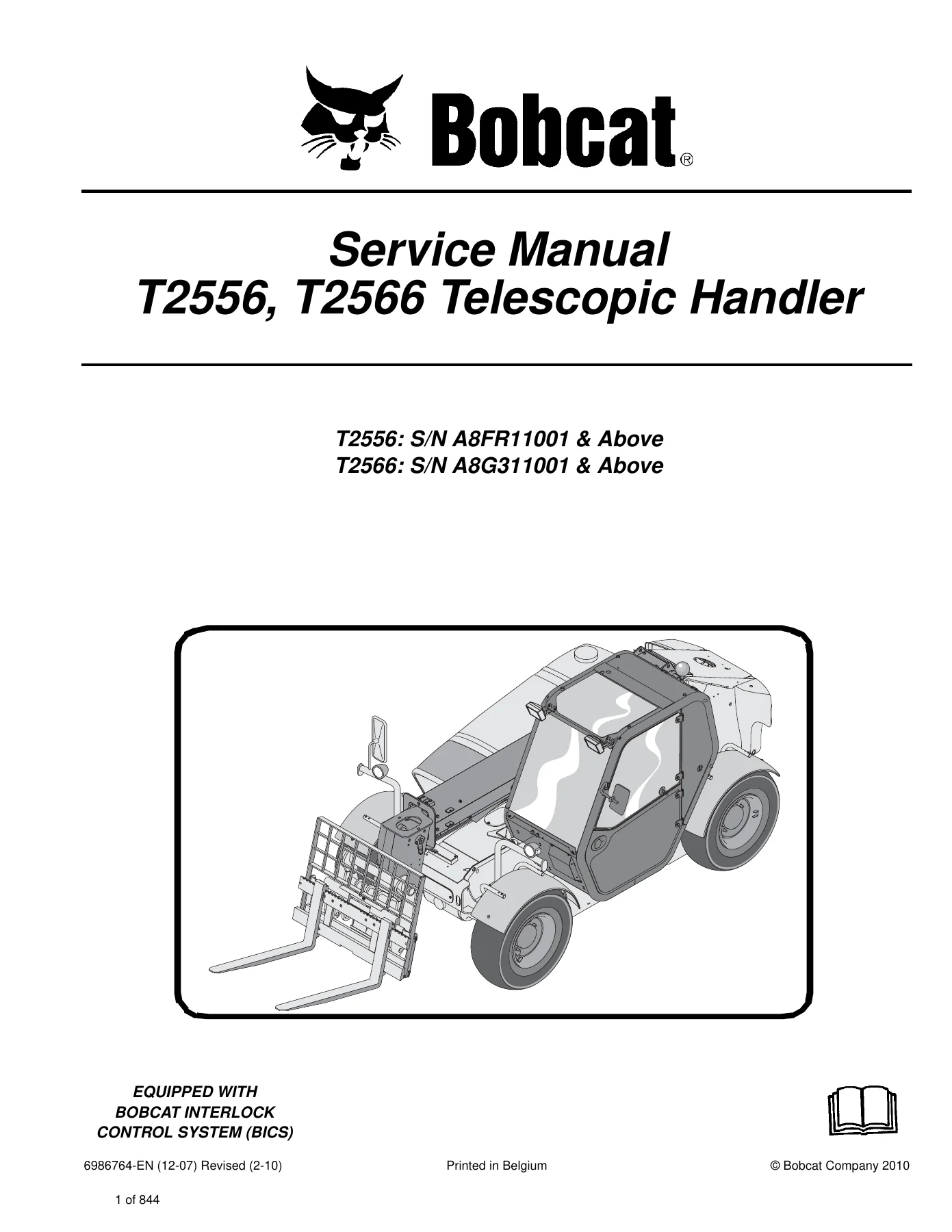
Bobcat T2556 T2566 Telescopic Handler Service Manual 6986764 Revised 2010 PDF
$49.95 Original price was: $49.95.$29.95Current price is: $29.95.
Complete 844-page service manual for Bobcat T2556 and T2566 Telescopic Handlers, covering servicing, adjustment, troubleshooting, hydraulic and hydrostatic systems, drive components, electrical analysis, engine service, HVAC and specifications. Applies to T2556 S/N A8FR11001 & Above and T2566 S/N A8G311001 & Above.
Description
Bobcat T2556 T2566 Telescopic Handler Service Manual 6986764 Revised 2010 PDF
The Bobcat T2556 T2566 Telescopic Handler Service Manual 6986764 Revised 2010 PDF is an extensive mechanic’s service reference for the T2556 and T2566 telescopic handlers. At 844 pages, it provides the servicing and adjustment procedures needed for the machine and its component parts and systems, with detailed photographs, component illustrations, hydraulic diagrams, troubleshooting information, test procedures, removal and installation instructions, and component disassembly and assembly sequences.
Coverage applies to T2556 S/N A8FR11001 & Above and T2566 S/N A8G311001 & Above. The manual also identifies the machines as equipped with the Bobcat Interlock Control System (BICS). Throughout the manual, procedures are organized by service section so technicians can move from routine maintenance and system diagnosis into individual component repair and adjustment work.
File Details
- Manual type: Service Manual
- Brand: Bobcat
- Models: T2556, T2566 Telescopic Handler
- Document number: 6986764-EN (12-07)
- Revision: Revised (2-10)
- Copyright: Bobcat Company 2010
- Language: English
- Pages: 844
- File format: PDF
- Applicable serial numbers: T2556 S/N A8FR11001 & Above; T2566 S/N A8G311001 & Above
Workshop Procedures and Diagnostic Coverage
This Bobcat T2556 and T2566 service manual goes well beyond routine maintenance. Major hydraulic cylinders and valves are covered with removal and installation procedures, parts identification, disassembly, inspection and assembly information. The hydraulic section includes procedures for the lift cylinder, bucket positioning cylinder, extension cylinder, tilt cylinder, front and rear steering cylinders, quick tach cylinder, steering valve and hydraulic control valve. Detailed exploded component illustrations help identify seals, O-rings, wear rings, pistons, rods, head glands, springs, spools and related internal components during repair.
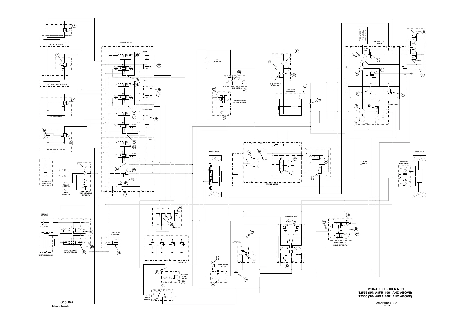
Hydraulic diagnosis is supported by troubleshooting charts, system schematics, testing instructions and adjustment procedures. The manual includes main relief valve testing and adjustment, port relief valve adjustment, steering mode valve work, pilot pressure lock-out valve testing and other hydraulic control procedures. The hydraulic schematic identifies the boom, telescopic and tilt circuits, steering, service and parking brakes, travel motor, pumps, hydraulic reservoir, fan motor, quick tach and optional hydraulic functions.
The hydrostatic section provides troubleshooting for drive-system complaints and explains hydrostatic circuit functions, along with service information for the hydrostatic drive motor and pump. Procedures progress from fault diagnosis into removal, component identification, disassembly and reassembly where applicable. This makes the Bobcat T2556 T2566 Telescopic Handler Service Manual 6986764 Revised 2010 PDF useful when the repair involves more than replacing an external service item.
Maintenance and Machine Service Information
The maintenance section provides a structured service schedule and procedures for frequently serviced areas of the machine. It covers engine oil and filter replacement, air cleaner elements, fuel filters, engine cooling system care, hydraulic and hydrostatic fluid and filter service, axle and differential lubricant checks, lubrication points, tyre maintenance and attachment-frame inspection. It also explains safe lifting and blocking, use of the approved boom stop, machine transport and towing procedures.
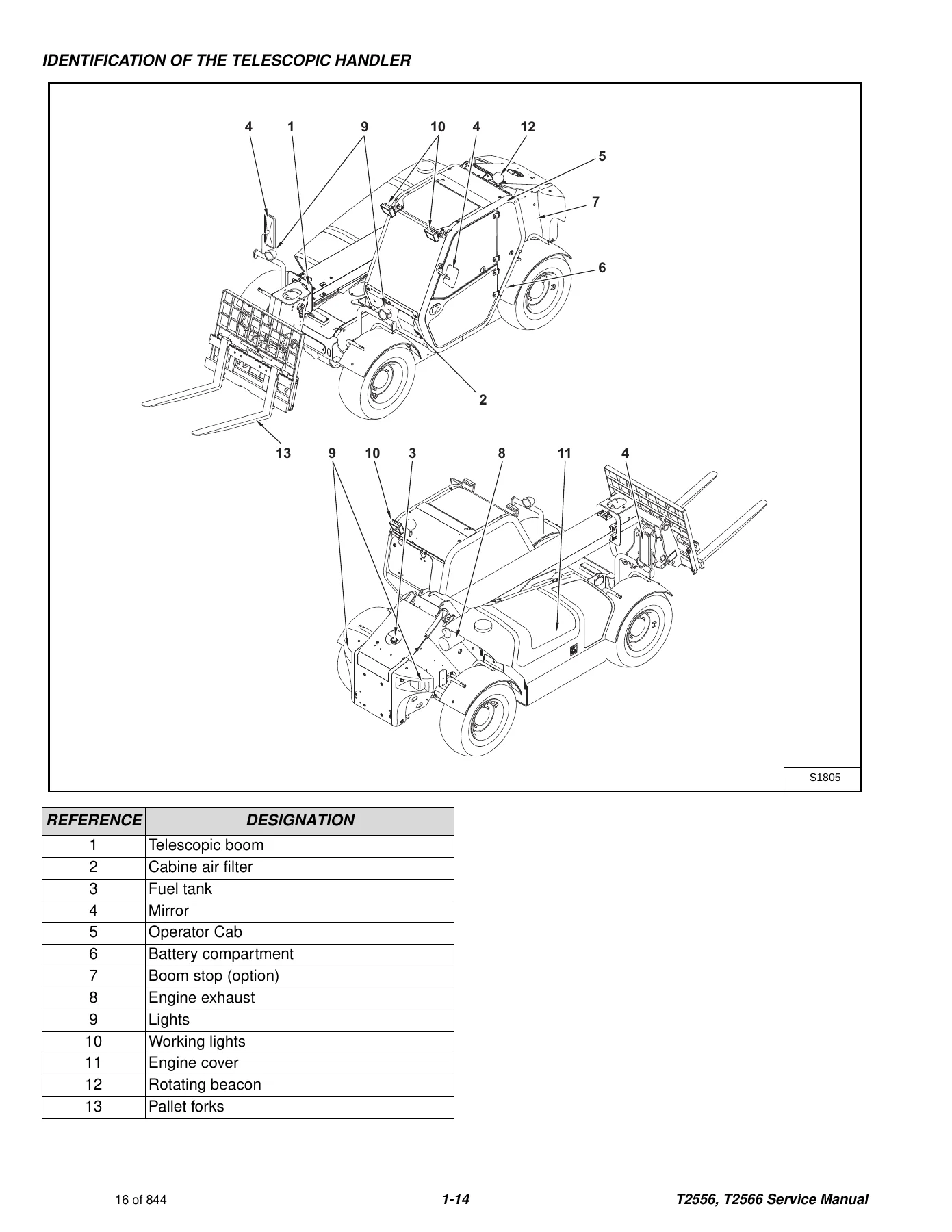
Service illustrations show the actual locations of filters, drains, fill points, cylinders, pivots, valves, electrical components and other service points. These visual references are particularly useful when dismantling assemblies or confirming hose, tubeline, connector and component locations before installation.
Chapters Covered
- Safety and Maintenance
- Lifting and blocking the telescopic handler; operator cab and emergency exit; transporting, loading, unloading and fastening; towing procedures; service schedule; air cleaner service; engine cooling system; fuel system; engine lubrication; hydraulic/hydrostatic fluid and filter service; front and rear axle lubrication; machine lubrication; attachment frame; tyre maintenance; spark arrester muffler; approved boom stop; engine cover.
- Hydraulic System
- Hydraulic system information and troubleshooting; lift cylinder; bucket positioning cylinder; extension cylinder and tubeline tray; tilt cylinder; front and rear steering cylinders; drive box; main relief valve; quick tach cylinder; port relief valves; steering mode valve block; brake valve; gear pump; fan motor; hydraulic reservoir; steering valve; hydraulic control valve; joystick; parking brake; pilot pressure lock out valve; accumulator; tow valve; front auxiliary hydraulic pressure release valve; flow control valve.
Complete PDF Bookmark TreeComplete Bookmarks
The complete bookmarks in the “Bobcat T2556 T2566 Telescopic Handler Service Manual 6986764 Revised 2010 PDF” are as follows:
MAINTENANCE SAFETYp. 3CONTENTSp. 5+FOREWORDp. 7
FOREWORDp. 9SAFETY INSTRUCTIONSp. 11+FIRE PREVENTIONp. 12
Maintenancep. 12Operationp. 12Electricalp. 12Hydraulic Systemp. 13Fuelingp. 13Startingp. 13Spark Arrester Exhaust Systemp. 13Welding And Grindingp. 13Fire Extinguishersp. 13+SERIAL NUMBER LOCATIONp. 14
Telescopic Handler Serial Numberp. 14Engine Serial Numberp. 14Other Serial Numbersp. 14DELIVERY REPORTp. 15IDENTIFICATION OF THE TELESCOPIC HANDLERp. 16+SAFETY AND MAINTENANCEp. 17
+LIFTING AND BLOCKING THE TELESCOPIC HANDLERp. 19
Procedurep. 19+OPERATOR CABp. 21
Emergency Exitp. 21Cab Doorp. 22Cab Door Windowp. 22+TRANSPORTING THE TELESCOPIC HANDLERp. 23
Loading And Unloadingp. 23Fasteningp. 23+TOWING THE TELESCOPIC HANDLERp. 25
Procedurep. 25SERVICE SCHEDULEp. 27+AIR CLEANER SERVICEp. 29
Replacing Filter Elementp. 29+ENGINE COOLING SYSTEMp. 31
Cleaning The Cooling Systemp. 31Checking The Coolant Levelp. 31Replacing The Coolantp. 32+FUEL SYSTEMp. 33
Fuel Specificationsp. 33Filling The Fuel Tankp. 33Fuel Filterp. 33+ENGINE LUBRICATION SYSTEMp. 35
Checking Engine Oilp. 35Oil Chartp. 35Replacing Oil And Filterp. 36+HYDRAULIC / HYDROSTATIC SYSTEMp. 37
Checking And Adding Fluidp. 37Replacing Hydraulic / Hydrostatic Filterp. 37Replacing Hydraulic Fluidp. 38+AXLES (FRONT AND REAR)p. 39
Checking Oil Level (Planetary Carrier)p. 39Draining Oil (Planetary Carrier)p. 39Checking Oil Level (Rear Differential)p. 40Draining Oil (Rear Differential)p. 40Checking Oil Level (Front Differential)p. 41Draining Oil (Front Differential)p. 41Checking Oil (Drive Box)p. 42Draining Oil (Drive Box)p. 42+LUBRICATIONp. 43
Procedurep. 43+ATTACHMENT FRAMEp. 47
Inspection And Maintenancep. 47+TYRE MAINTENANCEp. 49
Wheel Nutsp. 49Tyre Mountingp. 49Tyre Rotationp. 49+SPARK ARRESTER MUFFLERp. 51
Cleaningp. 51+APPROVED BOOM STOPp. 53
Installing The Approved Boom Stopp. 53Removing The Approved Boom Stopp. 53+ENGINE COVERp. 55
Opening And Closing The Engine Coverp. 55+HYDRAULIC SYSTEMp. 57
+HYDRAULIC SYSTEM INFORMATIONp. 64
Troubleshooting Chartp. 67HYDRAULIC SCHEMATICSp. 61Tightening Proceduresp. 68+LIFT CYLINDERp. 70
Removal And Installationp. 70Parts Identificationp. 75Disassemblyp. 76Assemblyp. 80+BUCKET POSITIONING CYLINDERp. 84
Removal And Installationp. 84Parts Identificationp. 89Disassemblyp. 90Assemblyp. 94+EXTENSION CYLINDERp. 98
Cylinder Group Removal And Installationp. 98Upper Tubeline Removalp. 100Upper Tubeline Installationp. 102Extension Cylinder Removal And Installationp. 104Tubeline Tray Disassemblyp. 106Tubeline Tray Assemblyp. 107Parts Identificationp. 110Disassemblyp. 111Assemblyp. 115+TILT CYLINDERp. 118
Removal And Installationp. 118+TILT CYLINDERp. 119
Parts Identificationp. 120Disassemblyp. 121Assemblyp. 126+STEERING CYLINDER (FRONT)p. 132
Removing The Steering Cylinderp. 132Installing The Steering Cylinderp. 133Disassembling The Steering Cylinderp. 135Assembling The Steering Cylinderp. 136+STEERING CYLINDER (REAR)p. 140
Removing The Steering Cylinderp. 140Installing The Steering Cylinderp. 141Disassembling The Steering Cylinderp. 143Assembling The Steering Cylinderp. 145+DRIVE BOXp. 148
Parts Identificationp. 148Disassemblyp. 149Assemblyp. 153Special Toolsp. 156+MAIN RELIEF VALVEp. 158
Testing And Adjustmentp. 158Removal And Installationp. 159+QUICK TACH CYLINDERp. 160
Removal And Installationp. 160Parts Identificationp. 162Disassemblyp. 163Assemblyp. 166+PORT RELIEF VALVESp. 168
Adjustment Procedurep. 168+STEERING MODE VALVE BLOCKp. 170
Removal And Installationp. 170Parts Identificationp. 172Disassemblyp. 173Solenoid Testingp. 175Assemblyp. 175+BRAKE VALVEp. 178
Removal And Installationp. 178Disassembly And Assemblyp. 179+GEAR PUMPp. 182
Removal And Installationp. 182Parts Identificationp. 184Disassembly And Assemblyp. 185+FAN MOTORp. 192
Removal And Installationp. 192Parts Identificationp. 196Disassembly And Assemblyp. 197+HYDRAULIC RESERVOIRp. 200
Removal And Installationp. 200+STEERING VALVEp. 202
Removal And Installationp. 202Parts Identificationp. 203Disassemblyp. 204Inspectionp. 210Assemblyp. 211+HYDRAULIC CONTROL VALVEp. 218
Troubleshooting Chart (Controllers)p. 218Telescoping Valve Section Troubleshootingp. 219Auxiliary Valve Section Troubleshootingp. 223Troubleshooting Chart (Control Valve)p. 227Removal And Installationp. 228Parts Identificationp. 232Disassembly And Assemblyp. 233End Housing Disassembly And Assemblyp. 234Lifting Valve Section Disassembly And Assemblyp. 235Tilting Valve Section Disassembly And Assemblyp. 240Telescoping Valve Section Disassembly And Assemblyp. 246Auxiliary Valve Section Disassembly And Assemblyp. 258Inlet-Outlet Valve Section Disassembly And Assemblyp. 269+JOYSTICKp. 274
Removal And Installationp. 274+PARKING BRAKEp. 276
Parking Brake Valve Removal And Installationp. 276Parking Brake Valve Disassembly And Assemblyp. 277+PILOT PRESSURE LOCK OUT VALVEp. 280
Testingp. 280Removal And Installationp. 281Disassembly And Assemblyp. 282+ACCUMULATORp. 284
Removal And Installationp. 284+TOW VALVEp. 286
Removal And Installationp. 286Disassembly And Assemblyp. 287+FRONT AUXILIARY HYDRAULIC PRESSURE RELEASE VALVEp. 292
Removal And Installationp. 292Disassembly And Assemblyp. 293+FLOW CONTROL VALVEp. 298
Removal And Installationp. 298+HYDROSTATIC SYSTEMp. 300
+HYDROSTATIC SYSTEM INFORMATIONp. 302
Troubleshooting Chartp. 302Replenishing Valve Functionp. 303+OIL COOLERp. 304
Descriptionp. 304+HYDROSTATIC DRIVE MOTORp. 306
Removal And Installationp. 306Parts Identificationp. 307Disassemblyp. 310Inspectionp. 321Assemblyp. 323+HYDROSTATIC PUMPp. 336
Removal And Installationp. 336Parts Identificationp. 337Disassemblyp. 342Inspectionp. 354Assemblyp. 358Charge pressure checking procedurep. 373Charge pressure adjusting procedurep. 373+DRIVE SYSTEMp. 374
+TROUBLESHOOTINGp. 376
Chartp. 376+AXLE AND DIFFERENTIAL (FRONT)p. 378
General Informationp. 378Planetary Carrier And Wheel Hub Parts Identificationp. 378Planetary Carrier Disassembly And Assemblyp. 379Wheel Hub Disassembly And Assemblyp. 381Steering Knuckle Disassembly And Assemblyp. 383Axle Housing / Drive Axle Disassemblyp. 385Brake Group Parts Identificationp. 389Brake Group Disassemblyp. 390Differential Parts Identificationp. 393Differential Disassembly And Assemblyp. 394Pinion Group Parts Identificationp. 397Pinion Group Disassemblyp. 398Pinion Group Assemblyp. 399Brake Group Assemblyp. 404Axle Housing / Drive Axle Assembyp. 407Special Toolsp. 410+AXLE AND DIFFERENTIAL (REAR)p. 412
General Informationp. 412Planetary Carrier And Wheel Hub Parts Identificationp. 412Planetary Carrier Disassemblyp. 413Steering Knuckle Parts Identificationp. 417Steering Knuckle Disassemblyp. 418Differential Parts Identificationp. 422Differential Disassemblyp. 423Bevel Pinion Parts Identificationp. 428Bevel Pinion Disassemblyp. 429Bevel Pinion Assemblyp. 433Differential Assemblyp. 442Steering Knuckle Assemblyp. 446Planetary Carrier Assemblyp. 452Special Toolsp. 457+FRONT AXLEp. 460
Removalp. 460Installationp. 465+AXLE TOE-INp. 470
Adjustmentp. 470+PARKING BRAKEp. 472
Releasing The Brake For Towingp. 472Re-Activating The Brakep. 473+STEERING ANGLE ADJUSTMENTp. 474
Adjustmentp. 474+DRIVESHAFTp. 476
Removal And Installationp. 476+SERVICE BRAKEp. 478
Descriptionp. 478Bleeding The Brake Circuitp. 478+REAR AXLEp. 480
Removalp. 480Installationp. 483+MAIN FRAMEp. 488
+OPERATOR CAB (S/N A8FR12999 & BELOW, S/N A8G312999 & BELOW)p. 490
Removal And Installationp. 490+OPERATOR CAB (S/N A8FR13000 & ABOVE, S/N A8G313000 & ABOVE)p. 498
Removal And Installationp. 498+OPERATOR SEATp. 506
Removal And Installationp. 506+BOOM ASSEMBLYp. 508
Removal And Installationp. 508+INNER BOOMp. 512
Removalp. 512Installationp. 514+WEAR PADS (FRONT)p. 516
Removal And Installationp. 516+WEAR PADS (REAR)p. 518
Removalp. 518Installationp. 518+ENGINE COVERp. 520
Gas Cylinder Removal And Installationp. 520Removal And Installationp. 520+AIR INTAKE COWLINGp. 522
Removal And Installationp. 522+FUEL TANKp. 524
Removal And Installationp. 524+QUICK TACHp. 528
Removal And Installationp. 528+REAR WEIGHTSp. 530
Removal And Installationp. 530+FENDERp. 532
Removal And Installationp. 532+JOYSTICK PANEL (S/N A8FR12999 & BELOW, S/N A8G312999 & BELOW)p. 534
Removal And Installationp. 534+JOYSTICK PANEL (S/N A8FR13000 & ABOVE, S/N A8G313000 & ABOVE)p. 536
Removal And Installationp. 536+DASH COVER / STEERING COLUMN COVER (S/N A8FR12999 & BELOW, S/N A8G312999 & BELOW)p. 538
Removal And Installationp. 538+DASH COVER / STEERING COLUMN COVER (S/N A8FR13000 & ABOVE, S/N A8G313000 & ABOVE)p. 542
Removal And Installationp. 542+ELECTRICAL SYSTEM AND ANALYSISp. 546
+ELECTRICAL SYSTEM INFORMATION (S/N A8FR12999 & BELOW, S/N A8G312999 & BELOW)p. 567
Troubleshooting Chartp. 567Descriptionp. 568Fuses, Diodes And Relaysp. 568ELECTRICAL SCHEMATICS (S/N 13000 & ABOVE)p. 548ELECTRICAL SCHEMATICS (S/N 12001 – 12999)p. 557+ELECTRICAL SYSTEM INFORMATION (S/N A8FR13000 & ABOVE, S/N A8G313000 & ABOVE)p. 571
Troubleshooting Chartp. 571Descriptionp. 572Fuses, Diodes And Relaysp. 572+BATTERYp. 575
Removal And Installationp. 575Servicingp. 576Using A Booster Battery (Jump Starting)p. 577+ALTERNATORp. 579
Removal And Installationp. 579Adjusting The Alternator Beltp. 580+STARTERp. 581
Removal And Installationp. 581Parts Identificationp. 582Disassemblyp. 583Inspection And Repairp. 588Assemblyp. 592+LIGHTSp. 597
Rear Light Removal And Installationp. 597Front Light Removal And Installationp. 598+TRAVEL / SIGNAL LEVER (S/N A8FR12999 & BELOW, S/N A8G312999 & BELOW)p. 601
Removal And Installationp. 601+TRAVEL / SIGNAL LEVER (S/N A8FR13000 & ABOVE, S/N A8G313000 & ABOVE)p. 603
Removal And Installationp. 603+INSTRUMENT PANELp. 605
Removal And Installationp. 605+SWITCH PANEL (S/N A8FR12999 & BELOW, S/N A8G312999 & BELOW)p. 607
Removal And Installationp. 607Parts descriptionp. 608+SWITCH PANEL (S/N A8FR13000 & ABOVE, S/N A8G313000 & ABOVE)p. 611
Removal And Installationp. 611Parts descriptionp. 612+BRAKE LIGHT SWITCHp. 615
Removal And Installationp. 615Adjustmentp. 615+FRONT WIPER MOTORp. 617
Removal And Installationp. 617+TOP WIPER MOTORp. 621
Removal And Installationp. 621+REAR WIPER MOTORp. 623
Removal And Installationp. 623+PEDAL ASSEMBLYp. 625
Removal And Installationp. 625Disassembly And Assemblyp. 626+INCHING SWITCHp. 631
Removal And Installationp. 631Adjustmentp. 631+SERVICE SOFTWAREp. 633
Connecting The Laptop Computerp. 633Entering The Service Softwarep. 634Monitor Screenp. 635Warnings Screenp. 637Calibrate Inch Pedalp. 638Calibrate Creep Potentiometerp. 639Program / Update Susmic Controllerp. 641+ENGINE SERVICEp. 643
+TROUBLESHOOTINGp. 647
Chartp. 647+ENGINE SPEED CONTROLp. 649
Removal And Installationp. 649+MUFFLERp. 651
Removal And Installationp. 651+AIR CLEANERp. 653
Housing Removal And Installationp. 653+OIL COOLER / RADIATORp. 655
Removal And Installationp. 655Disassembly And Assemblyp. 658+ENGINE AND ENGINE MOUNTSp. 661
Removal And Installationp. 661+ENGINE COMPONENTS AND TESTINGp. 665
Fuel Injection Pump Removalp. 665Fuel Injection Pump Installationp. 668Fuel Injectors Removal And Installationp. 671Checking The Fuel Lift Pumpp. 673Fuel Lift Pump Removal And Installationp. 674Compression Checkingp. 674Glow Plugs Checkingp. 675Glow Plugs Removal And Installationp. 676+ENGINE TIMINGp. 677
Procedurep. 677+ENGINE / HYDROSTAT ASSEMBLYp. 679
Removal And Installationp. 679+FLYWHEEL AND HOUSINGp. 693
Removal And Installationp. 693Ring Gear Removalp. 696Ring Gear Installationp. 696+RECONDITIONING THE ENGINEp. 697
Turbo Charger Troubleshootingp. 697Turbo Charger Descriptionp. 698Turbo Charger Removal And Installationp. 698Exhaust Manifold Removal And Installationp. 700Fuel Injector Cover Removal And Installationp. 700Rocker Cover Removal And Installationp. 701Cylinder Head Removalp. 702Cylinder Head Inspectionp. 704Cylinder Head Installationp. 705Rocker Shaft Disassembly And Assemblyp. 708Valve Removalp. 708Valve Springs Checkingp. 709Valve Depth Checkingp. 709Valve Guides Checkingp. 710Valve Guide Removalp. 711Valve Guide Installationp. 711Valves Checkingp. 712Cutting A Valve Seatp. 712Valve Seat Assemblyp. 713Changing Valve Springs (With Cylinder Head Installed)p. 714Valve Clearance Adjustmentp. 715Timing Case And Drive Assembly Descriptionp. 716Timing Cover Removalp. 716Timing Cover Installationp. 716Crankshaft Pulley Removal And Installationp. 716Front Oil Seal Removal And Installationp. 716Timing Case And Gear Removalp. 717Timing Case And Gear Installationp. 718Camshaft And Tappets Removalp. 720Camshaft And Tappets Installationp. 721Pistons And Connecting Rods Descriptionp. 722Pistons And Connecting Rods Removalp. 722Pistons And Connecting Rods Disassemblyp. 724Piston Ring End Gapp. 724Piston Ring Installationp. 724Piston Ring Groove Clearancep. 725Connecting Rod Inspectionp. 726Connecting Rod Bushing Replacementp. 726Piston And Connecting Rod Assemblyp. 726Piston And Connecting Rod Installationp. 726Checking Piston Heightp. 728Crankshaft And Bearings Descriptionp. 728Crankshaft And Bearings Removalp. 728Inspection Of Crankshaft And Bearingsp. 730Crankshaft And Bearings Installationp. 731Rear Oil Seal Removalp. 732Rear Oil Seal Housing Positioningp. 732Rear Oil Seal Installationp. 733Checking Crankshaft End Playp. 733Cooling System Descriptionp. 734Thermostat Removal and Installationp. 735Thermostat Testingp. 736Lubricating Oil Cooler Removal And Installationp. 736Water Pump Removalp. 736Water Pump Installationp. 736Engine Lubrication System Descriptionp. 737Oil Filter Adapter Removal And Installationp. 738Oil Pan Removal And Installationp. 738Oil Screen And Pick-up Tubep. 739Oil Pump Removalp. 739Oil Pump Installationp. 740Oil Pump Disassembly And Assemblyp. 741Oil Pressure Relief Valve Disassembly And Assemblyp. 741Engine Block Descriptionp. 742Engine Block Disassembly And Assemblyp. 742Piston Cooling Jet Removalp. 743Piston Cooling Jet Installationp. 743Piston Cooling Jet Alignmentp. 743Inspectionp. 743Cylinder Liner Inspectionp. 744Cylinder Liner Removalp. 745Cylinder Liner Installationp. 746+HEATING, VENTILATION, AIR CONDITIONINGp. 747
+AIR CONDITIONING SYSTEM FLOWp. 749
Principlesp. 749Chartp. 750+COMPONENTSp. 751
Identificationp. 751+SAFETYp. 755
Safety Equipmentp. 755+REGULAR MAINTENANCEp. 757
Filter Element Removal And Installationp. 757Compressor Drive Belt Inspectionp. 757Cleaning The Condenserp. 758+BASIC TROUBLESHOOTINGp. 759
Poor A/C Performancep. 759Compressor Drive Belt Inspectionp. 760Checking The Electrical Systemp. 761+GENERAL AIR CONDITIONING SERVICE GUIDELINESp. 769
Compressor Oilp. 769Compressor Oil Checkp. 769Component Replacement And Refrigeration Leaksp. 771SYSTEM TROUBLESHOOTING CHARTp. 773+TEMPERATURE / PRESSUREp. 777
Chartp. 777+AIR CONDITIONING SERVICEp. 779
Chartp. 779+SYSTEM CHARGING AND RECLAMATIONp. 781
Reclamation Procedurep. 781Charging Procedure With A Manifold Gauge Setp. 784Charging Procedurep. 785+COMPRESSORp. 787
Removal And Installationp. 787Compressor Clutch Disassembly And Assemblyp. 788+CONDENSER (S/N A8FR12999 & BELOW, S/N A8G312999 & BELOW)p. 793
Removal And Installationp. 793+CONDENSER (S/N A8FR13000 & ABOVE, S/N A8G313000 & ABOVE)p. 795
Removal And Installationp. 795+RECEIVER / DRIERp. 797
Removal And Installationp. 797+PRESSURE SWITCHp. 799
Removal And Installationp. 799+EVAPORATOR / BLOWER UNIT (S/N A8FR12999 & BELOW, S/N A8G312999 & BELOW)p. 801
Removal And Installationp. 801+EVAPORATOR / BLOWER / HEATER UNIT (S/N A8FR13000 & ABOVE, S/N A8G313000 & ABOVE)p. 803
Removal And Installationp. 803+EXPANSION VALVE (S/N A8FR12999 & BELOW, S/N A8G312999 & BELOW)p. 805
Removal And Installationp. 805+EXPANSION VALVE (S/N A8FR13000 & ABOVE, S/N A8G313000 & ABOVE)p. 807
Removal And Installationp. 807+HEATER ASSEMBLYp. 809
Removal And Installationp. 809Fan Removal And Installationp. 810Core Removal And Installationp. 811+SPECIFICATIONSp. 813
+TELESCOPIC HANDLER SPECIFICATIONSp. 815
Dimensional Specificationsp. 815Performance Specificationsp. 816Enginep. 816Fan Pumpp. 816Controlsp. 816Drive Systemp. 817Tyresp. 817Capacitiesp. 817Hydraulic Systemp. 818Electrical Systemp. 818Instrument Panelp. 818+ENGINE SPECIFICATIONSp. 819
Generalp. 819Cylinder Headp. 819Valve Guidesp. 819Exhaust Valvesp. 820Intake Valvesp. 820Valve Springsp. 820Rocker Shaft, Rockers And Bushingsp. 821Pistons And Piston Ringsp. 821Connecting Rods And Bearingsp. 822Crankshaftp. 822Crankshaft Re-Grind Datap. 823Main Bearingsp. 824Thrust Washersp. 824Camshaft And Thrust Washerp. 824Cylinder Blockp. 824Cylinder Linersp. 825Fuel Injection Pumpp. 825Fuel Injectorsp. 825Fuel Lift Pumpp. 825Timing Case And Timing Gearsp. 826Oil Pump, Gear And Relief Valvep. 827Turbochargerp. 827Flywheelp. 827Water Pump And Thermostatp. 828Engine Torque Componentp. 829+MACHINE TORQUE SPECIFICATIONSp. 831
Axlep. 831Boomp. 831Drive Boxp. 831Drive Motorp. 831Enginep. 832Hydraulic Pumpp. 832+TORQUE SPECIFICATIONS FOR BOLTSp. 833
Torque for General SAE Boltsp. 833Torque For General Metric Boltsp. 834+HYDRAULIC CONNECTION SPECIFICATIONSp. 835
O-ring Face Seal Connectionp. 835Straight Thread O-ring Fittingp. 835Tubelines And Hosesp. 835Port Seal Fittingp. 836+HYDRAULIC / HYDROSTATIC FLUID SPECIFICATIONSp. 837
Specificationsp. 837+CONVERSIONSp. 839
Decimal And Millimeter Equivalentsp. 839U.S. To Metric Conversionp. 839ALPHABETICAL INDEXp. 841+SERVICE MANUAL REVISIONp. 843
Revision No: T2556, T2566 – 1p. 843 - Hydrostatic System
- Hydrostatic system information and troubleshooting; replenishing valve function; oil cooler; hydrostatic drive motor; hydrostatic pump and related service procedures.
- Drive System
- Drive-system troubleshooting; axle and differential service, including front axle information; drive-system components and associated removal, installation and repair procedures.
- Main Frame
- Operator cab service with procedures divided by applicable serial-number groups, together with major frame-mounted machine components and assemblies.
- Electrical System and Analysis
- Electrical system information and troubleshooting; serial-number-specific electrical coverage; fuses, diodes and relays; charging, starting and wiring-related diagnosis; electrical component and circuit analysis.
- Engine Service
- Engine troubleshooting; engine speed control; engine-related service components; cooling and exhaust-related assemblies; engine/hydrostat assembly removal and installation; engine service procedures and torque data.
- Heating, Ventilation, Air Conditioning
- Air conditioning system flow and principles; HVAC component identification; safety; basic troubleshooting; electrical checks; general air-conditioning service; system charging and reclamation; compressor and heater-related service.
- Specifications
- Telescopic handler dimensional and performance specifications; engine information; machine torque specifications; hydraulic connection specifications; hydraulic/hydrostatic fluid information and other service specifications.
- Alphabetical Index
- Reference index for locating systems, components and procedures throughout the manual.
Together, these chapters provide a broad repair path from scheduled maintenance and initial fault finding through system testing, adjustment, component removal and internal repair. The manual repeatedly combines written procedures with photographs, illustrations, exploded views, schematics and specified measurements or torque values so work can be followed in the context of the actual T2556 and T2566 assemblies.
Hydraulic, Electrical and Engine Reference
The hydraulic information is particularly detailed. A full hydraulic schematic identifies the major pumps, valves, cylinders, motor and control circuits. The manual records a hydraulic reservoir system capacity of 31.7 Gal. (120 L), along with pump-flow and pressure information used during system diagnosis and adjustment. The main relief valve procedure includes use of a hydraulic tester, fluid warming and pressure testing rather than relying only on symptom descriptions.
Engine information identifies the PERKINS 1104D-44TA. The hydraulic schematic data records 74.5 kW @2200 rpm and 410 Nm @1400 rpm, with an engine speed range shown from 850 rpm minimum to 2400 rpm maximum. Engine service is integrated with the rest of the machine procedures, including the engine/hydrostat assembly, cooling, lubrication, fuel and related service work.
The electrical section provides separate information where the machine configuration changes by serial number. It covers the 12 volt negative-earth charging system, fuse, diode and relay locations, troubleshooting and circuit diagnosis. This is complemented by the HVAC section, where electrical checks, component identification and air-conditioning troubleshooting are included alongside mechanical service procedures.
Detailed Component Repair
A major strength of the Bobcat T2556 T2566 telescopic handler service manual is the amount of component-level work illustrated step by step. Cylinder sections show how assemblies are removed from the machine, how hoses and pivot pins are handled, how individual cylinders are dismantled, and where seals, wear rings, O-rings and internal components fit during assembly. Similar depth appears in drive box, valve and steering work.
IMAGES PREVIEW
The extension-cylinder section, for example, includes cylinder-group removal, upper tubeline removal and installation, tubeline tray disassembly and assembly, individual cylinder removal, parts identification, disassembly and reassembly. Correct tubeline positioning measurements and fastening instructions are included where required. Steering-cylinder procedures cover removal from the axle, tie-rod or steering-bar connections, internal sealing components and reassembly. The drive-box section provides an exploded parts identification drawing followed by disassembly, assembly and special-tool information.
Safety information is incorporated throughout the service procedures. Instructions address supporting the boom, depressurizing hydraulic components, protecting against fluid injection, handling batteries and fuel, welding precautions, machine blocking and checking correct function after repair. The manual’s foreword specifically directs operating instructions, starting procedures and daily checks to the separate Operation & Maintenance Manual; this service manual is focused on mechanic-level servicing, adjustment and repair of the machine and its systems.
Repair Your T2556 or T2566 with the Correct Service Information
The Bobcat T2556 T2566 Telescopic Handler Service Manual 6986764 Revised 2010 PDF gives you the procedures needed to diagnose system faults, perform scheduled service, remove and install assemblies, rebuild many hydraulic components, test and adjust hydraulic functions, trace electrical problems, service the drive and engine systems, and work with the heating and air-conditioning system. Having the correct procedures, diagrams, measurements, pressure settings and torque specifications available while the machine is being repaired helps reduce guesswork and provides a consistent reference from diagnosis through final assembly.
Your manual is supplied as an instant PDF download after purchase. There is no physical book and no shipping delay. Open the PDF on a computer, tablet or phone, keep it available in the workshop, and print the pages or procedures you need for the job.
What Our Customers Say
🌟 Related Products
Discover more professional manuals for your equipment


Reviews
There are no reviews yet.