
★ TRUSTED BY 321,897+ PROFESSIONALS WORLDWIDE
🏢
Trusted Business
Verified & Licensed
🛡️
Virus Free Files
100% Safe Downloads
🔒
Secure Payment
SSL Protected
Instant Delivery
Available Immediately
Sale!

Bobcat T40140 T40170 Telescopic Handler Service Manual 6986768 (2010)

Original price was: $41.95.Current price is: $24.95.

Shop service manual for Bobcat T40140 and T40170 telescopic handlers, S/N A8GA11001 and A8GB11001 and above. Covers maintenance, hydraulics, hydrostatic drive, axles, electrical analysis, Perkins 1104D-44TA engine work, HVAC, and specifications in an 862-page PDF.

Instant PDF Download
Available immediately
💾
Save to Your Device
Download & keep forever
🛡️
Antivirus Scanned
100% virus-free
🌍
Trusted Worldwide
175,000+ customers

Description

Bobcat T40140 T40170 Telescopic Handler Service Manual 6986768 (2010)

This Bobcat T40140 T40170 Telescopic Handler Service Manual 6986768 (2010) is written for the mechanic who services the T40140 and T40170 telescopic handlers. It gives servicing and adjustment procedures for the machine and its component parts and systems, and it is intended to be used together with the Operation and Maintenance Manual for starting, daily checks, and operator routines. Machines in this publication carry the Bobcat Interlock Control System (BICS) and are identified by serial numbers S/N A8GA11001 and above and S/N A8GB11001 and above. Publication 6986768-EN was issued 08-08 and revised 02-10, printed in Belgium, and copyrighted by Bobcat Company in 2010.

File Details

  • Manual type: Service Manual
  • Brand / models: Bobcat T40140 and T40170 telescopic handlers
  • Serial ranges: S/N A8GA11001 and above; S/N A8GB11001 and above
  • Language: English
  • Page count: 862
  • File format: PDF
  • Document number: 6986768-EN (08-08) Revised (02-10)
  • Copyright: Bobcat Company 2010

Machines And Systems Covered

Both models share the same Perkins 1104D-44TA turbo-charged four-cylinder diesel and the same hydrostatic four-wheel-drive layout. Rated capacity is 4000 kg on each machine. Lift height on tyres is 13430 mm on the T40140 and 17430 mm on the T40170; on stabilisers those figures become 13610 mm and 17180 mm. Maximum reach on tyres is 9800 mm versus 13730 mm. Unladen weight with no attachment is 10000 kg on the T40140 and 10790 kg on the T40170. The hydraulic pump is engine driven at 25 GPM (95 L/min) with system pressure of 3843 PSI (265 Bar). Travel is infinitely variable through a hydrostatic piston pump and one fully reversing hydrostatic motor, with low range 0-8 km/h and high range 0-30 km/h. Steering uses a wheel with three mode selections: front-wheel, all-wheel, and crab. Boom, tilt, and auxiliary functions are commanded from an electric joystick with switches. Standard tyres are four Dunlop 400/80 x 24 156B units, inflated to 4,25 bar on the T40140 and 4,75 bar on the T40170 when used with the rigid pallet frame and forks shown in the dimensional drawings.

Fluid capacities in the specification section are identical across both models: 140 L fuel tank (diesel Grade No. 2 or Grade No. 1), 145 L hydraulic/hydrostatic complete circuit and 77 L tank only (EQUIVIS ZS 46), 17 L engine cooling system with a 50/50 ethylene glycol mixture for -34°F (-37°C) freeze protection, 8,5 L engine lubrication circuit, 6,7 L front axle central casing, 6,6 L rear axle central casing, and 0,8 L each in the front reduction gearbox, front axle transfer box, and rear planetary carrier using Bobcat axle fluid P/N 100032-06A. The electrical system uses a 14,2 Volt 70 A alternator with internal regulator, a 12 V 105 Ah 720 A battery, and a 12 V 2,8 kW starter, with centralized fuse, relay and diode protection plus separate electronic boxes for hydrostatic transmission control and for stabiliser, CDDL and AMA functions.

Chapters Covered

  • Safety and Maintenance — lifting and blocking; operator cab emergency exit, door and window; transporting and fastening; towing and park-brake bypass; service schedule; air cleaner; engine cooling; fuel system; engine lubrication; hydraulic/hydrostatic fluid and filters; front and rear axle oils; lubrication; attachment frame; tyre maintenance; spark arrester muffler; approved boom stop; engine cover; telescoping chain tension and wear
  • Hydraulic System — system information and troubleshooting; lift, bucket positioning, extension, tilt, front and rear steering, quick tach, frame leveling and stabiliser cylinders; drive box; main relief, port relief, flow control, brake, steering, steering-mode, parking-brake, pressure-reducing, accumulator and tow valves; gear pump; fan motor; hydraulic reservoir; hydraulic control valve and joystick; stabiliser control valve
  • Hydrostatic System — troubleshooting and replenishing valve function; combined radiator/oil cooler; hydrostatic drive motor removal, inspection and assembly; hydrostatic pump removal, inspection and assembly
  • Drive System — troubleshooting; front and rear axle and differential teardown (planetary carriers, steering knuckles, drive axles, brake system, differential, bevel pinion); front and rear axle R&I; axle toe-in; parking brake release for towing; steering angle; driveshaft; service brake bleeding
  • Main Frame — operator cab (split at S/N A8GA12999 / A8GB12999 and A8GA13000 / A8GB13000); seat; boom assembly, end boom, intermediate boom (second intermediate boom on T40170), boom tray and pivot link; front and rear wear pads; engine cover and air intake cowling; fuel tank; Quick Tach; front and rear weights; fender; dash and joystick panel variants; stabiliser frame
  • Electrical System and Analysis — electrical information and troubleshooting by serial group; fuses, diodes and relays; battery and jump starting; alternator and belt; starter; wiring diagrams including radio and man-platform circuits; monitor functions and fault codes; frame-leveling related sensors
  • Engine Service — troubleshooting chart; speed control cable; muffler; air cleaner housing; oil cooler/radiator; engine and mounts; fuel injection pump, injectors, lift pump, compression and glow plugs; engine timing; engine/hydrostat assembly; flywheel and housing; full engine reconditioning (turbocharger, cylinder head, valves, timing case, camshaft, pistons, crankshaft, oil pump, liners)
  • Heating, Ventilation, Air Conditioning — R134a system flow; compressor, condenser, receiver/drier, expansion valve and evaporator; regular maintenance; charging and reclamation; receiver/drier and pressure switch
  • Specifications — dimensional and performance data for T40140 and T40170; engine, fan pump, controls, drive, tyres, capacities, hydraulic and electrical data; Perkins engine rebuild limits; machine and general bolt torques; hydraulic connection specs; fluid specifications; conversions
  • Alphabetical Index

Complete PDF Bookmark Tree

Complete Bookmarks

The complete bookmarks in the “Bobcat T40140 T40170 Telescopic Handler Service Manual 6986768 (2010)” are as follows:

MAINTENANCE SAFETYp. 3
CONTENTSp. 5
FOREWORDp. 7
FOREWORDp. 9
SAFETY INSTRUCTIONSp. 11
FIRE PREVENTIONp. 12
Maintenancep. 12
Operationp. 12
Electricalp. 12
Hydraulic Systemp. 13
Fuelingp. 13
Startingp. 13
Spark Arrester Exhaust Systemp. 13
Welding And Grindingp. 13
Fire Extinguishersp. 13
SERIAL NUMBER LOCATIONp. 14
Telescopic Handler Serial Numberp. 14
Engine Serial Numberp. 14
Other Serial Numbersp. 14
DELIVERY REPORTp. 15
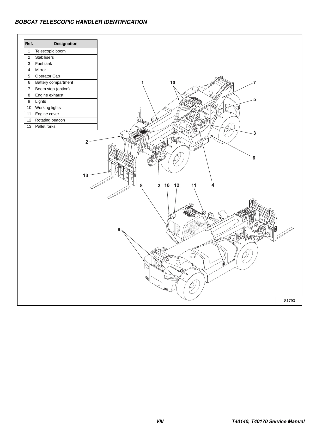
BOBCAT TELESCOPIC HANDLER IDENTIFICATIONp. 16
SAFETY AND MAINTENANCEp. 17
LIFTING AND BLOCKING THE TELESCOPIC HANDLERp. 19
Procedurep. 19
OPERATOR CABp. 21
Emergency Exitp. 21
Cab Doorp. 22
Cab Door Windowp. 22
TRANSPORTING THE TELESCOPIC HANDLERp. 23
Loading And Unloadingp. 23
Fasteningp. 23
TOWING THE TELESCOPIC HANDLERp. 25
Procedurep. 25
SERVICE SCHEDULEp. 27
AIR CLEANER SERVICEp. 29
Replacing Filter Elementp. 29
ENGINE COOLING SYSTEMp. 31
Cleaning The Cooling Systemp. 31
Checking The Coolant Levelp. 32
Replacing The Coolantp. 32
FUEL SYSTEMp. 35
Fuel Specificationsp. 35
Filling The Fuel Tankp. 35
Fuel Filterp. 35
ENGINE LUBRICATION SYSTEMp. 37
Checking Engine Oilp. 37
Oil Chartp. 37
Replacing Oil And Filterp. 38
HYDRAULIC / HYDROSTATIC SYSTEMp. 39
Checking And Adding Fluidp. 39
Replacing Hydraulic / Hydrostatic Filterp. 39
Replacing Hydraulic Fluidp. 40
AXLES (FRONT AND REAR)p. 41
Checking Oil Level (Planetary Carrier)p. 41
Draining Oil (Planetary Carrier)p. 41
Checking Oil Level (Rear Differential)p. 42
Draining Oil (Rear Differential)p. 42
Checking Oil Level (Front Differential)p. 42
Draining Oil (Front Differential)p. 43
LUBRICATIONp. 45
Procedurep. 45
ATTACHMENT FRAMEp. 49
Inspection And Maintenancep. 49
TYRE MAINTENANCEp. 51
Wheel Nutsp. 51
Tyre Mountingp. 51
Tyre Rotationp. 51
SPARK ARRESTER MUFFLERp. 53
Cleaningp. 53
APPROVED BOOM STOPp. 55
Installing The Approved Boom Stopp. 55
Removing The Approved Boom Stopp. 55
ENGINE COVERp. 57
Opening And Closing The Engine Coverp. 57
CHAIN CHECKING AND ADJUSTING PROCEDUREp. 59
Checking The Tension Of The Telescoping Chainsp. 59
HYDRAULIC SYSTEMp. 63
HYDRAULIC SCHEMATICSp. 67
HYDRAULIC SYSTEM INFORMATIONp. 69
Troubleshooting Chartp. 72
Tightening Proceduresp. 73
LIFT CYLINDERp. 75
Removal And Installationp. 75
Parts Identificationp. 78
Disassemblyp. 79
Assemblyp. 80
BUCKET POSITIONING CYLINDERp. 81
Removal And Installationp. 81
Parts Identificationp. 82
Disassemblyp. 83
Assemblyp. 83
EXTENSION CYLINDERp. 85
Cylinder Group Removal And Installationp. 85
Parts Identificationp. 88
Disassemblyp. 89
Assemblyp. 89
TILT CYLINDERp. 91
Removal And Installationp. 91
Parts Identificationp. 93
Disassemblyp. 94
Assemblyp. 94
STEERING CYLINDER (FRONT)p. 95
Removal And Installationp. 95
Disassemblyp. 97
Assemblyp. 98
STEERING CYLINDER (REAR)p. 103
Removalp. 103
Installationp. 105
Disassemblyp. 106
Assemblyp. 108
DRIVE BOXp. 111
Parts Identificationp. 111
Disassemblyp. 112
Assemblyp. 116
Special Toolsp. 119
MAIN RELIEF VALVEp. 121
Testingp. 121
Adjustmentp. 122
Removal and Installationp. 122
QUICK TACH CYLINDERp. 125
Removal And Installationp. 125
Parts Identificationp. 127
Disassemblyp. 128
Assemblyp. 128
FRAME LEVELING CYLINDERp. 129
Removal And Installationp. 129
Parts Identificationp. 131
Disassemblyp. 132
Assemblyp. 132
STEERING MODE VALVE BLOCKp. 133
Removal And Installationp. 133
Parts Identificationp. 135
Disassemblyp. 136
Solenoid Testingp. 138
Assemblyp. 138
BRAKE VALVEp. 141
Removal And Installationp. 141
Disassembly And Assemblyp. 142
GEAR PUMPp. 145
Removal And Installationp. 145
Parts Identificationp. 148
Disassembly And Assemblyp. 149
FAN MOTORp. 155
Removal And Installationp. 155
Parts Identificationp. 159
Disassembly And Assemblyp. 160
HYDRAULIC RESERVOIRp. 163
Removal And Installationp. 163
STEERING VALVEp. 165
Removal And Installationp. 165
Parts Identificationp. 166
Disassemblyp. 167
Inspectionp. 170
Assemblyp. 170
HYDRAULIC CONTROL VALVEp. 175
Checking Drain Pressurep. 175
Valve Section Troubleshooting (Auxiliary Section Example)p. 175
Removal And Installationp. 178
Parts Identificationp. 180
Section Removalp. 187
Section Disassembly And Assemblyp. 187
Inlet Section Disassembly And Assemblyp. 191
PORT RELIEF VALVESp. 195
Removal And Installationp. 195
FLOW CONTROL VALVEp. 197
Removal And Installationp. 197
JOYSTICKp. 199
Removal And Installationp. 199
PARKING BRAKEp. 201
Parking Brake Valve Removal And Installationp. 201
Parking Brake Valve Disassembly And Assemblyp. 202
PRESSURE REDUCING VALVEp. 205
Testingp. 205
Removal And Installationp. 206
ACCUMULATORp. 207
Removal And Installationp. 207
TOW VALVEp. 209
Removal And Installationp. 209
Disassembly And Assemblyp. 210
STABILISER CYLINDERp. 215
Removal And Installationp. 215
Parts Identificationp. 217
Disassemblyp. 218
Assemblyp. 219
STABILISER CONTROL VALVEp. 221
Parts Identificationp. 221
Removalp. 222
HYDROSTATIC SYSTEMp. 225
HYDROSTATIC SYSTEM INFORMATIONp. 227
Troubleshooting Chartp. 227
Replenishing Valve Functionp. 228
OIL COOLERp. 229
Descriptionp. 229
HYDROSTATIC DRIVE MOTORp. 231
Removal And Installationp. 231
Parts Identificationp. 232
Disassemblyp. 235
Inspectionp. 250
Assemblyp. 252
HYDROSTATIC PUMPp. 269
Removal And Installationp. 269
Parts Identificationp. 271
Disassemblyp. 275
Inspectionp. 285
Assemblyp. 289
DRIVE SYSTEMp. 303
TROUBLESHOOTINGp. 305
Chartp. 305
AXLE AND DIFFERENTIAL (FRONT)p. 307
General Informationp. 307
Planetary Carrier Parts Identificationp. 307
Planetary Carrier Disassemblyp. 308
Steering Knuckle And Drive Axle Parts Identificationp. 313
Steering Knuckle Disassemblyp. 314
Drive Axle Disassemblyp. 316
Brake System Parts Identificationp. 318
Brake System Disassemblyp. 319
Differential Parts Identificationp. 323
Differential Disassemblyp. 324
Bevel Pinion Parts Identificationp. 329
Bevel Pinion Disassemblyp. 330
Bevel Pinion Assemblyp. 333
Differential Assemblyp. 342
Brake System Assemblyp. 347
Drive Axle Assemblyp. 353
Steering Knuckle Assemblyp. 355
Planetary Carrier Assemblyp. 358
Special Toolsp. 362
AXLE AND DIFFERENTIAL (REAR)p. 363
General Informationp. 363
Planetary Carrier Parts Identificationp. 363
Steering Knuckle And Drive Axle Parts Identificationp. 369
Steering Knuckle Disassemblyp. 370
Differential And Bevel Pinion Parts Identificationp. 372
Differential Disassemblyp. 373
Bevel Pinion Disassemblyp. 377
Bevel Pinion Assemblyp. 380
Differential Assemblyp. 388
Steering Knuckle Assemblyp. 393
Planetary Carrier Assemblyp. 396
Special Toolsp. 400
FRONT AXLEp. 401
Removalp. 401
AXLE TOE-INp. 407
Adjustmentp. 407
PARKING BRAKEp. 409
Releasing The Brake For Towingp. 409
Re-Activating The Brakep. 410
STEERING ANGLE ADJUSTMENTp. 411
Adjustmentp. 411
DRIVESHAFTp. 413
Removal And Installationp. 413
SERVICE BRAKEp. 415
Descriptionp. 415
Bleeding The Brake Circuitp. 415
REAR AXLEp. 417
Removal And Installationp. 417
MAIN FRAMEp. 421
OPERATOR CAB (S/N A8GA12999 & BELOW, S/N A8GB12999 & BELOW)p. 423
Removal and Installationp. 423
OPERATOR CAB (S/N A8GA13000 & ABOVE, S/N A8GB13000 & ABOVE)p. 431
Removal And Installationp. 431
OPERATOR SEATp. 439
Removal And Installationp. 439
BOOM ASSEMBLYp. 441
Removal And Installationp. 441
END BOOMp. 445
Removalp. 445
Installationp. 447
WEAR PADS (FRONT)p. 449
Removalp. 449
Installationp. 450
WEAR PADS (REAR)p. 453
Removalp. 453
Installationp. 453
ENGINE COVERp. 455
Gas Cylinder Removal And Installationp. 455
Removal And Installationp. 455
AIR INTAKE COWLINGp. 457
Removal And Installationp. 457
FUEL TANKp. 459
Removal And Installationp. 459
QUICK TACHp. 463
Removal And Installationp. 463
REAR WEIGHTSp. 465
Removal And Installationp. 465
FENDERp. 467
Removal And Installationp. 467
FRONT WEIGHTp. 469
Removal And Installationp. 469
DASH COVER / STEERING COLUMN COVER (S/N A8GA12999 & BELOW, A8GB12999 & BELOW)p. 471
Removal And Installationp. 471
DASH COVER / STEERING COLUMN COVER (S/N A8GA13000 & ABOVE, S/N A8GB13000 & ABOVE)p. 475
Removal And Installationp. 475
JOYSTICK PANEL (S/N A8GA12999 & BELOW, A8GB12999 & BELOW)p. 479
Removal And Installationp. 479
JOYSTICK PANEL (S/N A8GA13000 & ABOVE, A8GB13000 & ABOVE)p. 481
Removal And Installationp. 481
INTERMEDIATE BOOMp. 483
Removal of the First Intermediate Boomp. 483
Installation of the First Intermediate Boomp. 484
Removal of the Second Intermediate Boom (T40170)p. 485
Installation of the Second Intermediate Boom (T40170)p. 486
BOOM TRAYp. 489
Removal And Installationp. 489
PIVOT LINKp. 493
Removal And Installationp. 493
STABILISER FRAMEp. 497
Removalp. 497
Installationp. 498
ELECTRICAL SYSTEM AND ANALYSISp. 501
ELECTRICAL SYSTEM INFORMATION (S/N A8HM12999 & BELOW, S/N A8HN12999 & BELOW)p. 579
Troubleshooting Chartp. 579
Descriptionp. 580
Fuses, Diodes And Relaysp. 580
Fuses And Diodesp. 582
Relaysp. 582
ELECTRICAL SCHEMATICS (S/N 13000 & ABOVE)p. 503
ELECTRICAL SCHEMATICS (S/N 12001 – 12999)p. 522
ELECTRICAL SCHEMATICS (S/N 11001 – 11999)p. 541
ELECTRICAL SYSTEM INFORMATION (S/N A8GA13000 & ABOVE, S/N A8GB13000 & ABOVE)p. 585
Troubleshooting Chartp. 585
Descriptionp. 586
Fuses, Diodes And Relaysp. 586
BATTERYp. 589
Removal And Installationp. 589
Servicingp. 590
Using A Booster Battery (Jump Starting)p. 591
ALTERNATORp. 593
Removal And Installationp. 593
Adjusting The Alternator Beltp. 594
STARTERp. 595
Removal And Installationp. 595
Parts Identificationp. 596
Disassemblyp. 597
Inspection And Repairp. 602
Assemblyp. 606
LIGHTSp. 611
Rear Light Removal And Installationp. 611
Front Light Removal And Installationp. 612
TRAVEL / SIGNAL LEVER (S/N A8GA12999 & BELOW, S/N A8GB12999 & BELOW)p. 615
Removal And Installationp. 615
TRAVEL / SIGNAL LEVER (S/N A8GA13000 & ABOVE, S/N A8GB13000 & ABOVE)p. 617
Removal And Installationp. 617
INSTRUMENT PANELp. 619
Removal And Installationp. 619
SWITCH PANEL (S/N A8GA12999 & BELOW, A8GB12999 & BELOW)p. 621
Removal And Installationp. 621
Parts descriptionp. 622
SWITCH PANEL (S/N A8GA13000 & ABOVE, A8GB13000 & ABOVE)p. 625
Removal And Installationp. 625
Parts descriptionp. 626
BRAKE LIGHT SWITCHp. 629
Removal And Installationp. 629
Adjustmentp. 629
FRONT WIPER MOTORp. 631
Removal And Installationp. 631
TOP WIPER MOTORp. 635
Removal And Installationp. 635
REAR WIPER MOTORp. 637
Removal And Installationp. 637
PEDAL ASSEMBLYp. 639
Removal And Installationp. 639
Disassembly And Assemblyp. 640
INCHING SWITCHp. 645
Removal And Installationp. 645
Adjustmentp. 645
SERVICE SOFTWAREp. 647
Connecting The Laptop Computerp. 647
Entering The Service Softwarep. 648
Monitor Screenp. 649
Warnings Screenp. 651
Calibrate Inch Pedalp. 652
Calibrate Creep Potentiometerp. 653
Program / Update Susmic Controllerp. 655
FRAME LEVEL SPEED SWITCHp. 657
Descriptionp. 657
Removalp. 657
Installationp. 658
ENGINE SERVICEp. 659
TROUBLESHOOTINGp. 663
Chartp. 663
ENGINE SPEED CONTROLp. 665
Removal And Installationp. 665
MUFFLERp. 667
Removal And Installationp. 667
AIR CLEANERp. 669
Housing Removal And Installationp. 669
OIL COOLER / RADIATORp. 671
Removal And Installationp. 671
Disassembly And Assemblyp. 674
ENGINE AND ENGINE MOUNTSp. 677
Removal And Installationp. 677
ENGINE COMPONENTS AND TESTINGp. 681
Fuel Injection Pump Removalp. 681
Fuel Injection Pump Installationp. 684
Fuel Injectors Removal And Installationp. 687
Checking The Fuel Lift Pumpp. 689
Fuel Lift Pump Removal And Installationp. 690
Compression Checkingp. 690
Glow Plugs Checkingp. 691
Glow Plugs Removal And Installationp. 692
ENGINE TIMINGp. 693
Procedurep. 693
ENGINE / HYDROSTAT ASSEMBLYp. 695
Removal And Installationp. 695
FLYWHEEL AND HOUSINGp. 709
Removal And Installationp. 709
Ring Gear Removalp. 712
Ring Gear Installationp. 712
RECONDITIONING THE ENGINEp. 713
Turbo Charger Troubleshootingp. 713
Turbo Charger Descriptionp. 714
Turbo Charger Removal And Installationp. 714
Exhaust Manifold Removal And Installationp. 716
Fuel Injector Cover Removal And Installationp. 716
Rocker Cover Removal And Installationp. 717
Cylinder Head Removalp. 718
Cylinder Head Inspectionp. 720
Cylinder Head Installationp. 721
Rocker Shaft Disassembly And Assemblyp. 724
Valve Removalp. 724
Valve Springs Checkingp. 725
Valve Depth Checkingp. 725
Valve Guides Checkingp. 726
Valve Guide Removalp. 727
Valve Guide Installationp. 727
Valves Checkingp. 728
Cutting A Valve Seatp. 728
Valve Seat Assemblyp. 729
Changing Valve Springs (With Cylinder Head Installed)p. 730
Valve Clearance Adjustmentp. 731
Timing Case And Drive Assembly Descriptionp. 732
Timing Cover Removalp. 732
Timing Cover Installationp. 732
Crankshaft Pulley Removal And Installationp. 732
Front Oil Seal Removal And Installationp. 732
Timing Case And Gear Removalp. 734
Timing Case And Gear Installationp. 735
Camshaft And Tappets Removalp. 737
Camshaft And Tappets Installationp. 738
Pistons And Connecting Rods Descriptionp. 739
Pistons And Connecting Rods Removalp. 739
Pistons And Connecting Rods Disassemblyp. 741
Piston Ring End Gapp. 741
Piston Ring Installationp. 741
Piston Ring Groove Clearancep. 742
Connecting Rod Inspectionp. 743
Connecting Rod Bushing Replacementp. 743
Piston And Connecting Rod Assemblyp. 743
Piston And Connecting Rod Installationp. 743
Checking Piston Heightp. 745
Crankshaft And Bearings Descriptionp. 745
Crankshaft And Bearings Removalp. 745
Inspection Of Crankshaft And Bearingsp. 747
Crankshaft And Bearings Installationp. 748
Rear Oil Seal Removalp. 749
Rear Oil Seal Housing Positioningp. 749
Rear Oil Seal Installationp. 750
Checking Crankshaft End Playp. 750
Cooling System Descriptionp. 751
Thermostat Removal and Installationp. 752
Thermostat Testingp. 753
Lubricating Oil Cooler Removal And Installationp. 753
Water Pump Removalp. 753
Water Pump Installationp. 753
Engine Lubrication System Descriptionp. 754
Oil Filter Adapter Removal And Installationp. 755
Oil Pan Removal And Installationp. 755
Oil Screen And Pick-up Tubep. 756
Oil Pump Removalp. 756
Oil Pump Installationp. 757
Oil Pump Disassembly And Assemblyp. 758
Oil Pressure Relief Valve Disassembly And Assemblyp. 758
Engine Block Descriptionp. 759
Engine Block Disassembly And Assemblyp. 759
Piston Cooling Jet Removalp. 760
Piston Cooling Jet Installationp. 760
Piston Cooling Jet alignmentp. 760
Inspectionp. 760
Cylinder Liner Inspectionp. 761
Cylinder Liner Removalp. 762
Cylinder Liner Installationp. 763
HEATING, VENTILATION, AIR CONDITIONINGp. 765
AIR CONDITIONING SYSTEM FLOWp. 767
Principlesp. 767
Chartp. 768
COMPONENTSp. 769
Identificationp. 769
SAFETYp. 773
Safety Equipmentp. 773
REGULAR MAINTENANCEp. 775
Filter Element Removal And Installationp. 775
Compressor Drive Belt Inspectionp. 775
Cleaning The Condenserp. 776
BASIC TROUBLESHOOTINGp. 777
Poor A/C Performancep. 777
Compressor Drive Belt Inspectionp. 778
Checking The Electrical Systemp. 779
GENERAL AIR CONDITIONING SERVICE GUIDELINESp. 785
Compressor Oilp. 785
Compressor Oil Checkp. 785
Component Replacement And Refrigeration Leaksp. 787
SYSTEM TROUBLESHOOTING CHARTp. 789
TEMPERATURE / PRESSUREp. 793
Chartp. 793
AIR CONDITIONING SERVICEp. 795
Chartp. 795
SYSTEM CHARGING AND RECLAMATIONp. 797
Reclamation Procedurep. 797
Charging Procedure With A Manifold Gauge Setp. 800
Charging Procedurep. 801
COMPRESSORp. 803
Removal And Installationp. 803
Compressor Clutch Disassembly And Assemblyp. 804
CONDENSER (S/N A8GA12999 & BELOW, S/N A8GB12999 & BELOW)p. 809
Removal And Installationp. 809
CONDENSER (S/N A8GA13000 & ABOVE, S/N A8GB13000 & ABOVE)p. 811
Removal And Installationp. 811
RECEIVER / DRIERp. 813
Removal And Installationp. 813
PRESSURE SWITCHp. 815
Removal And Installationp. 815
EVAPORATOR / BLOWER UNIT (S/N A8GA12999 & BELOW, S/N A8GB12999 & BELOW)p. 817
Removal And Installationp. 817
EVAPORATOR / BLOWER/HEATER UNIT (S/N A8GA13000 & ABOVE, S/N A8GB13000 & ABOVE)p. 819
Removal And Installationp. 819
EXPANSION VALVE (S/N A8GA12999 & BELOW, S/N A8GB12999 & BELOW)p. 821
Removal And Installationp. 821
EXPANSION VALVE (S/N A8GA13000 & ABOVE, A8GB13000 & ABOVE)p. 823
Removal And Installationp. 823
HEATER ASSEMBLYp. 825
Removal And Installationp. 825
Fan Removal And Installationp. 826
Core Removal And Installationp. 827
SPECIFICATIONSp. 829
TELESCOPIC HANDLER SPECIFICATIONSp. 831
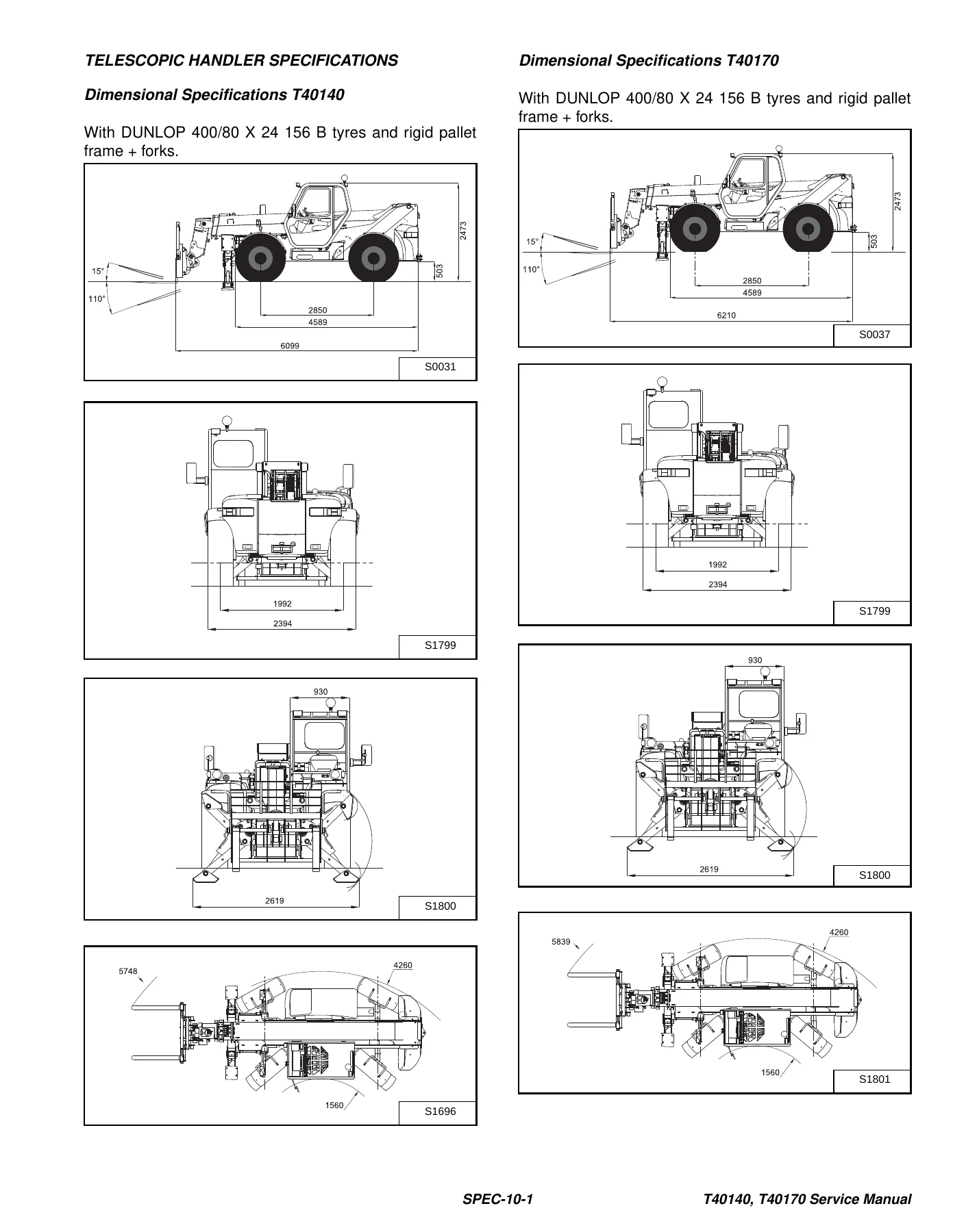
Dimensional Specifications T40140p. 831
Dimensional Specifications T40170p. 831
Performance Specificationsp. 832
Enginep. 832
Fan Pumpp. 832
Controlsp. 833
Drive Systemp. 833
Tyresp. 833
Capacitiesp. 834
Hydraulic Systemp. 834
Electrical Systemp. 834
Instrument Panelp. 834
ENGINE SPECIFICATIONSp. 835
Generalp. 835
Cylinder Headp. 835
Valve Guidesp. 835
Exhaust Valvesp. 836
Intake Valvesp. 836
Valve Springsp. 836
Rocker Shaft, Rockers And Bushingsp. 837
Pistons And Piston Ringsp. 837
Connecting Rods And Bearingsp. 838
Crankshaftp. 838
Crankshaft Re-Grind Datap. 839
Main Bearingsp. 840
Thrust Washersp. 840
Camshaft And Thrust Washerp. 840
Cylinder Blockp. 840
Cylinder Linersp. 841
Fuel Injection Pumpp. 841
Fuel Injectorsp. 841
Fuel Lift Pumpp. 841
Timing Case And Timing Gearsp. 842
Oil Pump, Gear And Relief Valvep. 843
Turbochargerp. 843
Flywheelp. 843
Water Pump And Thermostatp. 844
Engine Torque Componentp. 845
MACHINE TORQUE SPECIFICATIONSp. 847
Axlep. 847
Boomp. 847
Drive Boxp. 847
Drive Motorp. 847
Enginep. 848
Hydraulic Pumpp. 848
TORQUE SPECIFICATIONS FOR BOLTSp. 849
Torque for General SAE Boltsp. 849
Torque For General Metric Boltsp. 850
HYDRAULIC CONNECTION SPECIFICATIONSp. 851
O-ring Face Seal Connectionp. 851
Straight Thread O-ring Fittingp. 851
Tubelines And Hosesp. 851
Port Seal Fittingp. 852
HYDRAULIC / HYDROSTATIC FLUID SPECIFICATIONSp. 853
Specificationsp. 853
CONVERSIONSp. 855
Decimal And Millimeter Equivalentsp. 855
U.S. To Metric Conversionp. 855
ALPHABETICAL INDEXp. 857
SERVICE MANUAL REVISIONp. 861
Revision No: T40140, T40170 – 1p. 861

Taken together, the Bobcat T40140 T40170 Telescopic Handler Service Manual 6986768 (2010) is a shop-level repair book rather than an operator handbook. A technician can lift and block the machine, release the spring-applied front-axle park brake and turn the tow valve for short-distance recovery, then return those adjustments before returning the handler to work. The same book walks through boom-stop installation before major work, cab and boom removal (with serial-split cab and dash procedures), wear-pad and telescoping-chain service, complete cylinder and valve work, hydrostatic pump and motor overhaul, front and rear axle rebuilds with special tools, electrical diagnosis, Perkins 1104D-44TA in-frame and out-of-frame engine work, and R134a air-conditioning service.

Maintenance Intervals And Daily Work

The service schedule in the Bobcat T40140 T40170 service manual groups tasks at 10, 50, 100, 250, 500 and 1000 hours (or 12 months at the last interval). Daily and short-interval items include engine oil and hydraulic fluid level checks, lubrication of articulation pins, king pins, axle oscillation, attachment-frame pivots, tilt/lift cylinders, boom pivot, self-levelling/side-shift cylinder and structure, telescopic boom slides, door hinges and stabiliser cylinders, plus inspection of safety signs, treads, mirrors, seat belt, brakes, tyres, air filter indicator, cooling pack and hydraulic lines. Wheel nuts are specified at 221 ft.-lb. (300 N·m), with a first-24-hour check every 8 hours. Engine oil and filter, outer air filter, primary and secondary fuel filters, and the hydraulic filter are first-time-then-interval items. Hydraulic fluid and filter, axle fluid, boom wear blocks, pivot pins and bushings, and engine valve lash appear at the longer intervals. Coolant freeze protection is checked at -34°F (-30°C) in the schedule table, with a flush and premix replacement every two years. Air-cleaner service is condition-indicator driven: replace the outer element when the red ring shows, and replace the inner safety element every third outer change or if the indicator still flags after an outer change.

Hydraulic, Hydrostatic And Drive Work

Hydraulic chapters in this T40140 T40170 workshop manual cover more than hose replacement. Each major cylinder has removal, parts identification, disassembly and assembly steps. The drive box, gear pump and fan motor are fully torn down. Main relief testing and adjustment, control-valve drain-pressure checks, auxiliary-section troubleshooting, port relief and flow-control valves, the three-mode steering valve block with solenoid testing, brake valve, parking-brake valve, pressure-reducing valve, accumulator and tow valve are all documented. Stabiliser cylinders and the stabiliser control valve are included for machines so equipped. Hydrostatic work goes through replenishing-valve function, then complete disassembly, inspection and assembly of the drive motor (mounting bolts 140-155 ft.-lb. / 190-210 N·m) and the hydrostatic pump. Drive-system pages rebuild the front axle including the wet brake pack and bevel pinion, rebuild the rear axle and differential, set toe-in and steering angle, service the driveshaft, and bleed the service-brake circuit. Only the front axle has brakes; park-brake release for towing is a four-bolt, quarter-turn procedure with a matching reactivation sequence.

IMAGES PREVIEW

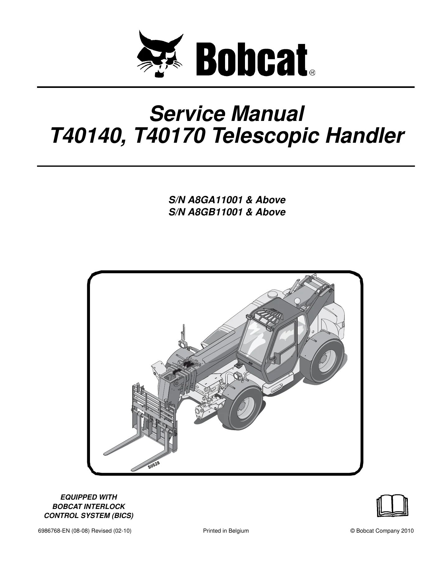
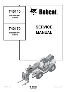
Bobcat T40140 T40170 Telescopic Handler Service Manual 6986768 (2010) — PDF page 1 preview
Bobcat T40140 T40170 Telescopic Handler Service Manual 6986768 (2010) — PDF page 16 preview
Bobcat T40140 T40170 Telescopic Handler Service Manual 6986768 (2010) — PDF page 831 preview

Engine, Electrical And Cab Climate

The Perkins 1104D-44TA section matches the performance sheet: turbo-charged, liquid-cooled diesel, 100 HP (74,5 kW) SAE net, four cylinders in line, 4.133 in. (105 mm) bore, 5.000 in. (127 mm) stroke, 18.2:1 compression, 269 in³ (4,4 L) displacement, firing order 1-3-4-2, clockwise rotation from the front, direct injection, maximum torque 410 N·m at 1400 rpm. Engine service in the Bobcat T40140 T40170 Telescopic Handler Service Manual 6986768 (2010) includes injection-pump R&I with TDC number-one timing pins, injector and lift-pump work, compression comparison between cylinders, glow-plug checks, combined engine/hydrostat removal, flywheel and ring-gear work, and a long reconditioning chapter covering turbocharger diagnosis, cylinder head and valve service (valves that fail spec are replaced, not ground), timing case and gears, camshaft and tappets, pistons and rings, crankshaft and bearings with re-grind data, oil pump and relief valve, piston cooling jets, and cylinder liner inspection and replacement. Electrical analysis covers charging and starting faults, fuse and relay maps, booster-battery procedure, alternator belt deflection, hydrostatic monitor screens (engine RPM, travel control position, battery voltage, propel curve, sensor voltage, brake-release switch) and related fault codes. HVAC pages explain R134a high- and low-side state changes through compressor, condenser, receiver/drier, expansion valve and evaporator, then move into belt and condenser service, electrical checks, reclamation and charging, and component replacement. Compressor oil is specified as 150-170 cc of PAG oil from the factory fill.

Use This Manual On The Job

The Bobcat T40140 T40170 Telescopic Handler Service Manual 6986768 (2010) supports scheduled maintenance, leak and overheating diagnosis, boom and attachment-frame work, cylinder and valve overhaul, hydrostatic pump and motor rebuild, axle and brake service, cab and boom structural R&I, electrical troubleshooting, Perkins 1104D-44TA testing and reconditioning, and R134a climate-system service. Following the printed pressures, torques, wear limits and serial-split procedures keeps lift capacity, travel control and interlock function inside the values Bobcat published for these handlers. After payment you receive the PDF immediately—no shipping—so you can open it on a phone, tablet or shop computer and print the pages you need at the machine.
Reviews

There are no reviews yet.

Be the first to review “Bobcat T40140 T40170 Telescopic Handler Service Manual 6986768 (2010)”

What Our Customers Say

★★★★★ Live reviews from customers
Loading customer reviews...
0
    0
    Your Cart
    Your cart is emptyReturn to Shop
    🛒
    Recently Purchased
    🕒 verified order