
Boonton 102D FM-AM Signal Generator Instruction Manual – PDF Download
Original price was: $34.95.$19.95Current price is: $19.95.
Complete Boonton 102D FM-AM Signal Generator instruction manual covering operation, theory, maintenance, calibration, troubleshooting, parts, and schematics. Instant PDF download.
Description
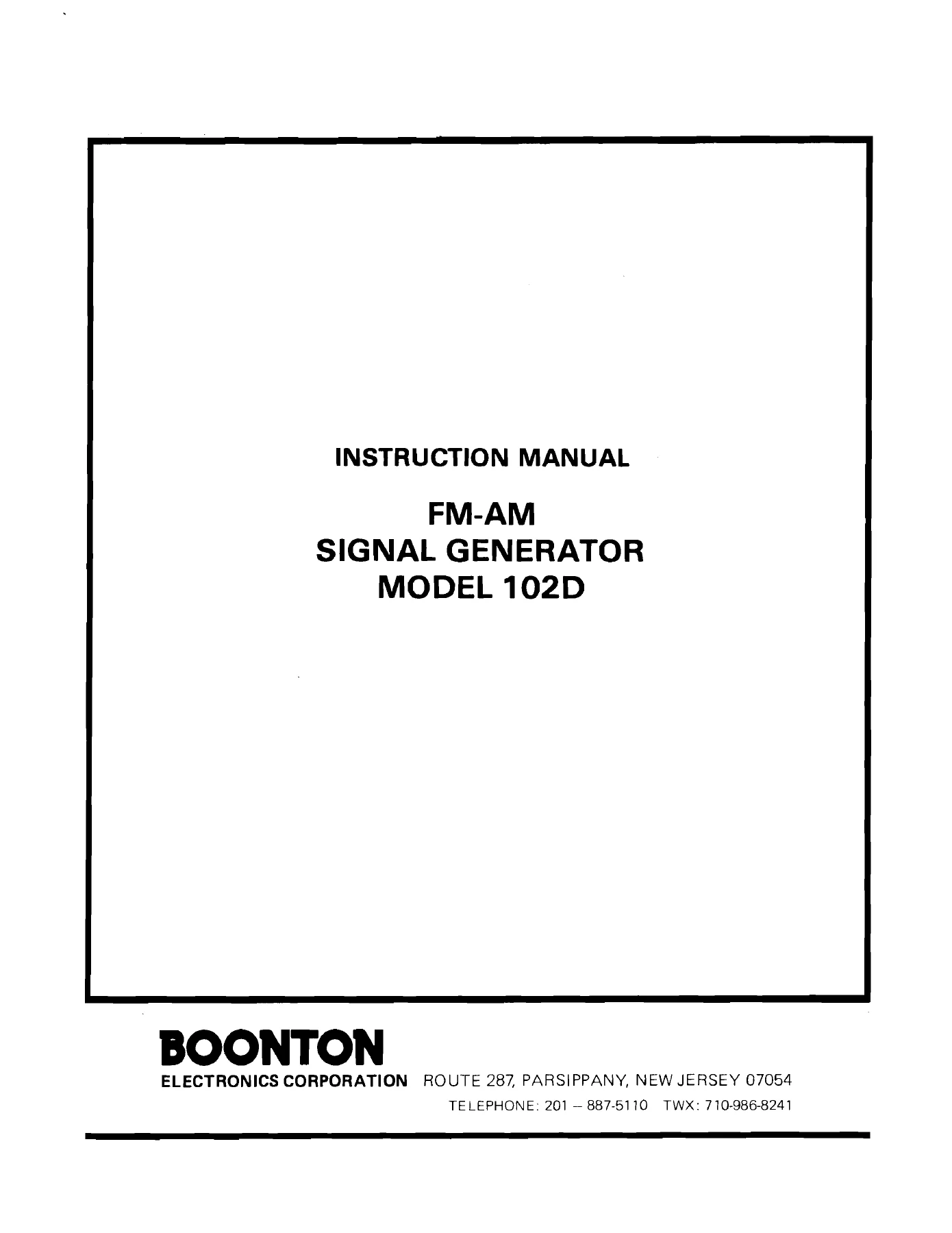
This Boonton 102D FM-AM Signal Generator Instruction Manual is the complete technical document for the Boonton Electronics Model 102D FM-AM signal generator. It covers the 0.45 to 520 MHz frequency range across five bands and provides the original operating, theory, maintenance, calibration, troubleshooting, parts, and schematic information needed to understand, operate, and service this precision instrument. Whether you are running performance checks, aligning the VFO, troubleshooting phase-lock circuits, or looking up a component on a schematic, this manual gives you the detailed guidance.
File Details
- Manual type: Instruction Manual
- Brand: Boonton Electronics Corporation
- Model: 102D FM-AM Signal Generator
- Language: English
- Page count: 130
- File format: PDF
Chapters Covered
- Section I – Introduction: Scope of Manual, Purpose and Use of Equipment, Options, Specifications, Outline Dimensions
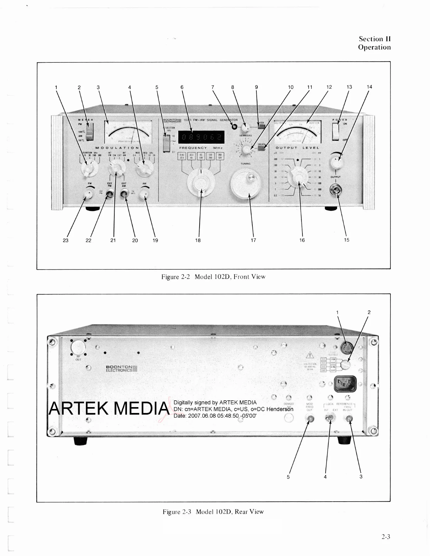
- Section II – Operation: Installation, Unpacking, Mounting, Power Requirements, Cable Connections, Operating Controls, Indicators and Connectors, Power Application, Preliminary Check, Operating Procedure, Output Frequency Selection, Phase-Locked Operation, Modulation Mode Selection, Adjustment of Modulation Levels, Adjustment of Output Level, Application Notes, Impedance Matching, IF Response, Avoidance and Identification of Harmonics, Visual Frequency Response Checks, EIA Sensitivity Measurement, Minimum Performance Checks, Frequency Accuracy Check, Frequency Range Check, Output Level Accuracy Check, Output Leveling Check, Spurious Output Check, Modulation Oscillator Output Check, Modulation Frequency Accuracy Check, Modulation Oscillator Distortion Check, FM Measurements, AM Measurements, Incidental AM with FM Check, Incidental FM with AM Check, Residual FM Check, Output Impedance Check, RF Leakage Check, Frequency Stability Check, Frequency Counter Stability Check, Single Sideband Total Noise Check
- Section III – Theory of Operation: Simplified Block Diagram, Frequency Generating Circuits, Phase-Lock Circuits, Signal Processing Circuits, Output Circuits, Modulation Circuits, Frequency Counter Circuits, Power Supply Circuits, Detailed Theory of Operation for each circuit group
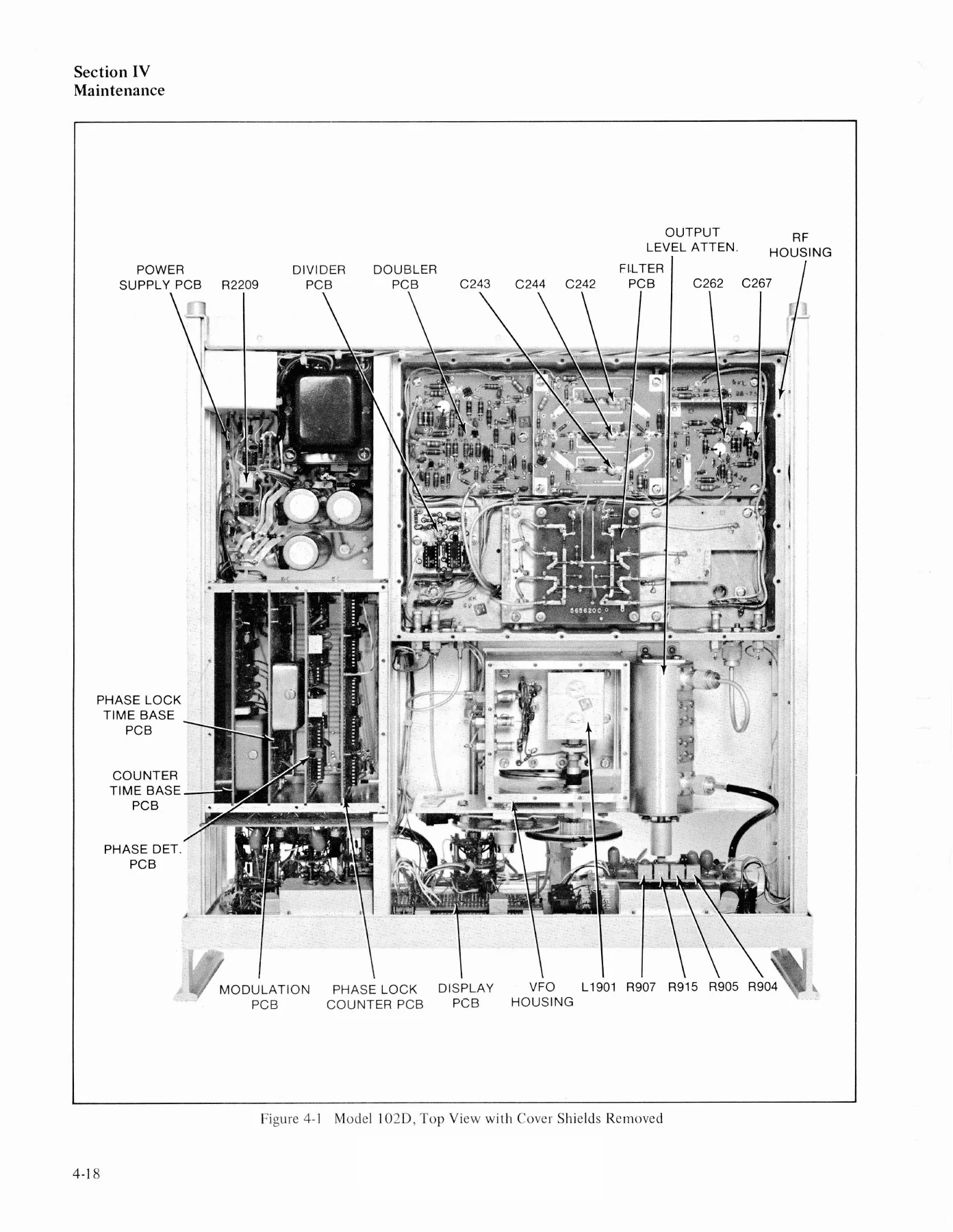
- Section IV – Maintenance: Test Equipment Required, Preliminary Inspection, Visual Check, Power Supply Check, Major Assembly Location, Trouble Localization, Symptomatic Troubleshooting, Systematic Troubleshooting, Alignment and Adjustment Procedures, Power Supply Adjustments, Modulation Oscillator Amplitude Adjustment, Counter Amplifier Gain Adjustment, Clock Frequency Adjustment, FM Deviation Tracking and Calibration, Band-Pass Filter Alignment, Band 5 Driver Adjustment, Band 1 Converter Alignment, Output Level Calibration, AM Calibration, Parts Removal, VFO Variable Inductor Removal, TUNING Control Drive Dial Cord Replacement, Varactor Tracking Capacitor Dial Cord Replacement, Voltage Measurements
- Section V – Parts List: Replaceable parts for frame, sub panel, rear panel, deviation switch, modulation switch, band switch, doubler PCB, VFO board, meter PCB, power supply PCB, output PCB, converter PCB, divider PCB, phase detector PCB, phase lock counter PCB, wide band amplifier PCB, and more
- Section VI – Schematic Diagrams: Main Frame, VFO Housing, Modulation PCB, Display PCB, Meter PCB, Power Supply PCB, RF Housing Interconnection, Doubler PCB, Filter Switch PCB, Converter PCB, Output PCB, Divider PCB, Phase-Lock Master PCB, Display Time Base PCB, Phase-Lock Time Base PCB, Phase Detector PCB, Phase-Lock Counter PCB, Wide Band Amplifier
The Boonton 102D FM-AM Signal Generator Instruction Manual is far more than a quick-start guide. It walks through the full signal path from the VFO and phase-lock circuits through signal processing, output leveling, modulation, frequency counting, and power supply. Maintenance chapters give systematic troubleshooting charts, voltage tables, alignment steps, and dial-cord replacement procedures. The parts list and full schematics make component-level repair practical. This is the document you want when the instrument needs calibration, when a band drops out, when phase lock will not hold, or when you need to verify performance against the original specifications.
What You Can Do With This Manual
Use the Boonton 102D FM-AM Signal Generator Instruction Manual to set up and operate the generator correctly, select output frequency and modulation modes, perform phase-locked operation, and adjust output level. It also supports detailed performance verification: frequency accuracy, frequency range, output level accuracy and leveling, spurious output, modulation oscillator output and distortion, FM sensitivity, FM bandwidth, AM sensitivity, AM bandwidth, AM accuracy, AM distortion, incidental AM and FM, residual FM, output impedance, RF leakage, frequency stability with and without phase lock, frequency counter stability, and single-sideband total noise. When repair is needed, the maintenance section helps you localize trouble by symptom, work through systematic troubleshooting charts for frequency generating, signal processing, output, modulation, frequency counter, and phase-lock circuits, then align and calibrate the instrument after repairs.
Why This Manual Matters
Working on a Boonton 102D without the original manual means guessing at test setups, control settings, voltage readings, and adjustment points. This manual provides the exact procedures, typical voltage measurements, component references, and schematic diagrams needed to do the job correctly. It covers options such as external modulation connectors, special internal modulation frequencies, demodulated AM output, RF output fusing, high-impedance AM and FM inputs, and external time base operation. The theory of operation explains how the VFO, binary divider, crystal oscillator, PIN diode switches, doublers, filters, and phase-lock loop work together, so troubleshooting is based on understanding rather than trial and error. The parts list and schematics help identify replacements and trace signals through every board.
Get the Boonton 102D FM-AM Signal Generator Instruction Manual Today
IMAGES PREVIEW
This Boonton 102D FM-AM Signal Generator Instruction Manual is delivered as an instant PDF download, so there is no shipping wait and no physical media to handle. Read it on a computer, tablet, or phone, and print the pages you need for the bench. With complete coverage of operation, theory, maintenance, calibration, troubleshooting, parts, and schematics, this manual helps you keep the Boonton 102D performing to specification and get it back on the bench quickly when problems arise.
Reviews
There are no reviews yet.