
IFR FM/AM-500A Communications Service Monitor Maintenance Manual 1984 PDF
Original price was: $39.95.$23.95Current price is: $23.95.
Complete 362-page IFR FM/AM-500A maintenance manual covering theory of operation, performance evaluation, calibration, troubleshooting, module testing, disassembly and full circuit schematics for the FM/AM-500A and FM/AM-500 service monitors.
Description
IFR FM/AM-500A Communications Service Monitor Maintenance Manual
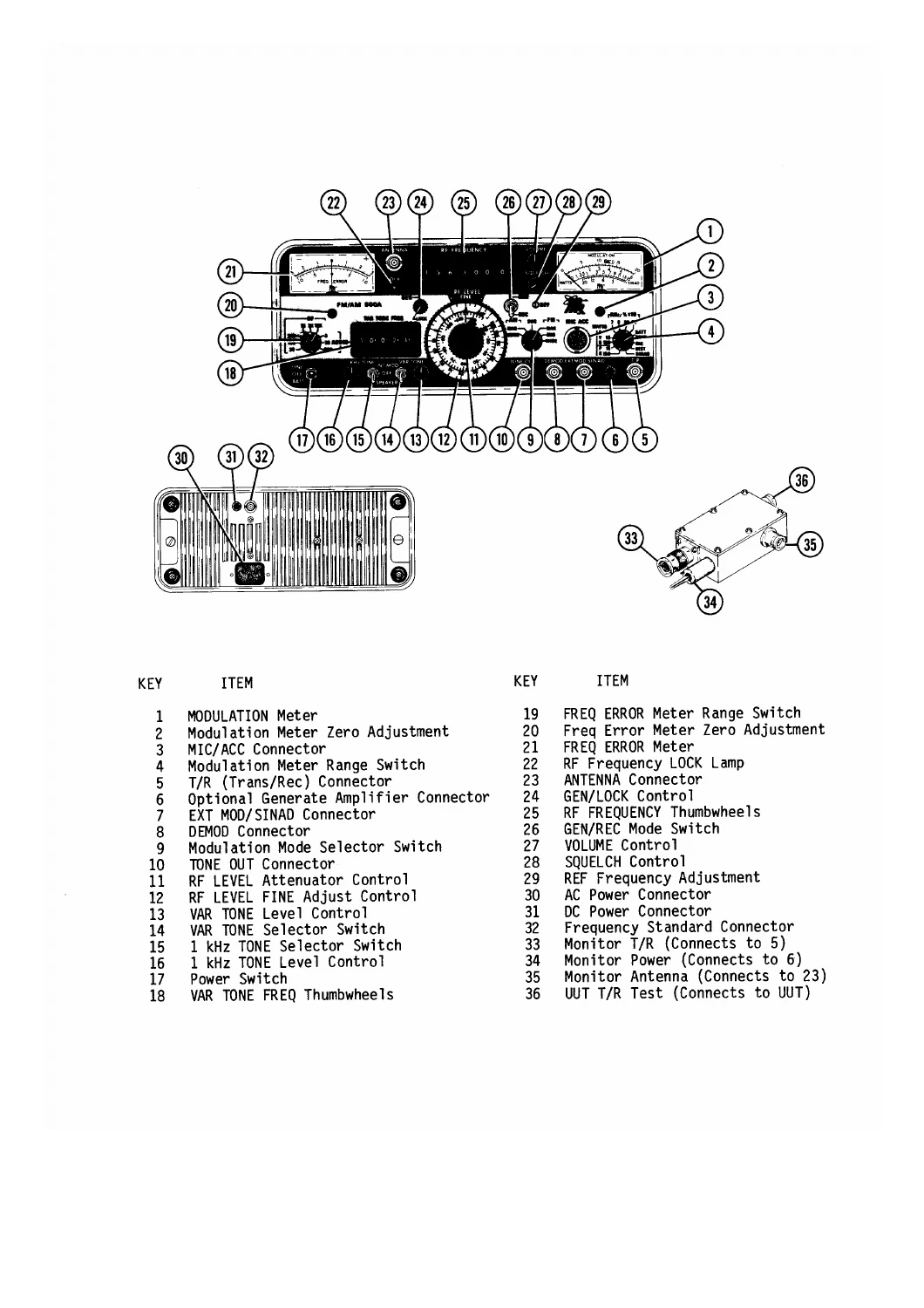
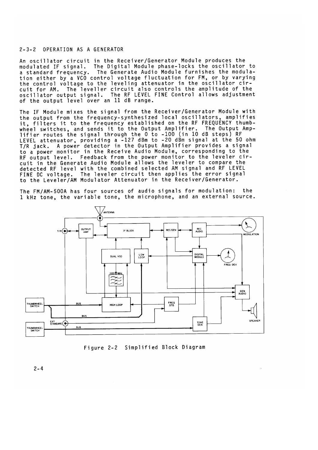
The IFR FM/AM-500A is a compact, lightweight communications service monitor built to generate and analyse both RF and audio frequencies, and this 362-page maintenance manual is the document that keeps it on the bench. It walks a technician through the set at every level: from a simplified signal-flow description of the whole instrument, down to individual circuits inside the enclosed modules, and back out again to the calibration and performance checks that prove the unit is working to specification.
Written around the FM/AM-500A but equally applicable to the FM/AM-500 where noted, this IFR FM/AM-500A maintenance manual is aimed at the person who has to service, test, repair or replace a major assembly or module within the test set, keep the operating condition at expected performance standards, and understand how the principles of operation relate both to the overall set and to individual circuits.
What This IFR FM/AM-500A Manual Covers
The manual opens by describing the electrical and mechanical configuration of the set so the technician can become familiar with its overall structure before touching a single adjustment. From there it moves into circuit theory on a simplified level using the accompanying block diagrams, then into practical bench work: functional checkout in generate and receive operation, step-by-step calibration for normal intervals or after parts replacement, and logical tabular troubleshooting procedures for isolating fault conditions inside the major electrical circuits.
Because the FM/AM-500A uses a modular electronic design, with circuits isolated inside mechanical module assemblies for shielding and access, a large part of this manual is devoted to getting those modules out and back in correctly, and to testing them on the bench once they are out. Mechanical assembly drawings are provided for all modules, along with component layout drawings for every PC board assembly and full circuit schematics for the module set.
Chapters and Sections Included
- Section 1 – Introduction: general description, electrical description, frequency selectors, meters, mode/bandwidth control, RF output level control, power requirements, frequency standards, mechanical design, reference designators, corrective maintenance procedures
- Section 2 – Theory of Operation: simplified theory of operation, intermodule systems theory, reference frequencies, frequency conversion modules, audio system, frequency error display, phase lock indicator circuit
- Section 3 – Performance Evaluation: test equipment requirements, mobile performance evaluation procedures, laboratory performance evaluation procedures for the tone generators, receiver, generate system, frequency error meters, modulation and power meter, SINAD meter and power meter
- Section 4 – Calibration: safety precautions, disassembly requirements, recommended calibration sequence, mechanical zeroing of the modulation and frequency error meters, power supply, 10 MHz oscillator, variable tone generator, frequency error meter, modulation meter, SINAD meter, power meter and generate output level
- Section 5 – Troubleshooting: how to use the tabular flowcharts, troubleshooting hints, safety precautions, power supply faults, receiver sensitivity and demodulation faults, generator carrier amplitude and frequency faults, variable generator control response, and phase lock system faults for the lock light, high loop and low loop
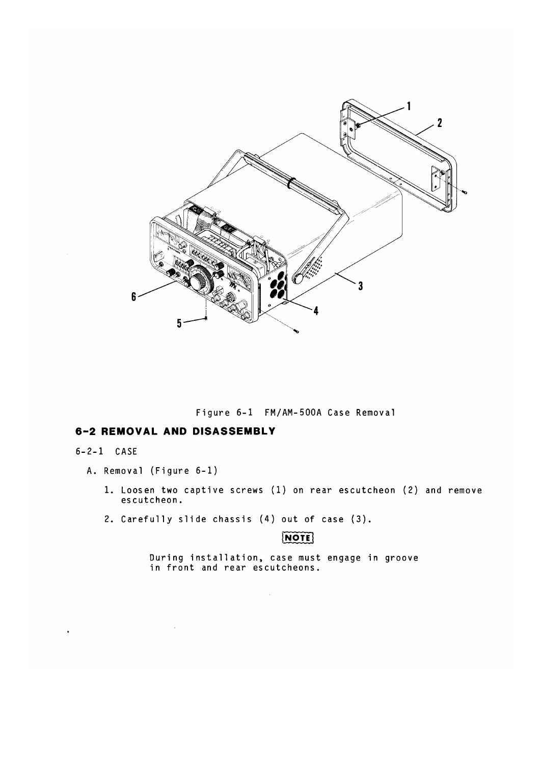
- Section 6 – Disassembly/Reassembly Procedures: case, battery, oven oscillator, frequency standard PC board, power supply PC board, 1120 MHz low pass filter, speaker, motherboard, audio PC boards, enclosed modules, output amplifier, IF module, dual VCO, rear panel, front panel, generate amplifier and RF level attenuator assembly
- Section 7 – Module Testing: power supply, IF module, dual VCO, high loop synthesizer, low loop synthesizer, receiver/generator, frequency standard, digital module, receive audio, generate audio, output amplifier, variable tone generator and optional generate amplifier
- Section 8 – Preventive Maintenance: external cleaning, internal cleaning and visual inspection
- Section 9 – PC Board Assemblies: component layout drawings for every PC board assembly in the set
- Section 10 – Circuit Schematics: coax interconnect, electrical interconnect, motherboard, power supply, frequency standard, front panel, switch assemblies, output amplifier, IF module, high loop, dual VCO, low loop, receiver/generator, receive audio, generate audio, variable tone generator, digital module and generate amplifier
- Appendices: specifications, test equipment, special test equipment, abbreviations and symbols, and repacking for shipment
Altogether this is a full maintenance document rather than a quick-start guide. It assumes a technician with a bench, a signal generator, a spectrum analyser and a frequency counter, and it gives that technician the block diagrams, calibration points, test connections, trimpot references and meter tolerances needed to bring an FM/AM-500A back to spec instead of guessing at it.
Coverage and Applicability
The designation “FM/AM-500A” is used throughout the manual when the discussion applies to both the FM/AM-500 and the FM/AM-500A. Where information applies to only one model, it is identified as “FM/AM-500 only” or “FM/AM-500A only”, so an owner of either set can use the same book. Certain procedures are further split by serial number — the output amplifier, for example, is documented separately for sets through S/N 3224 and for S/N 3225 and on, and the electrical interconnect schematics are divided prior to SN 2501 and SN 2501 and on.
The set itself covers RF frequency selection from 100 kHz to 999.9999 MHz in 100 Hz increments, a variable tone generator adjustable between 10 Hz and 9999.9 Hz in 0.1 Hz steps, an RF output level controlled by a 10 dB step attenuator with an 11 dB vernier, and a 10 MHz reference derived from a temperature-compensated crystal oscillator with optional oven oscillator or external standard. The maintenance manual addresses the circuitry behind all of it.
Why This IFR FM/AM-500A Maintenance Manual Matters
Correct procedures and correct specifications are the difference between a service monitor that returns to full accuracy and one that drifts quietly out of tolerance. This manual supplies the actual calibration sequence for interactive modules, the module replacement and alignment requirements, the specific output voltages expected at the power supply connector pins, the RF frequency error tolerances at each range setting, and the audio frequency error tolerances down to fractions of a hertz. Troubleshooting is handled as logical tabular flowcharts that lead from a symptom to a repairable module or PC board rather than to a pile of guesswork.
Safety content is included where it is needed, including warnings about the rear panel transformer carrying 120 or 240 VAC whenever the power cord is connected, and about the 12 VDC potential that exists at various rear panel points whenever the battery is installed or external AC or DC power is applied, regardless of the front panel power switch position.
Get the IFR FM/AM-500A Communications Service Monitor Maintenance Manual
With this IFR FM/AM-500A Communications Service Monitor Maintenance Manual on hand you can run performance evaluations in generate and receive modes, calibrate the 10 MHz oscillator, frequency error meter, modulation meter, SINAD meter, power meter and generate output level, isolate faults in the power supply, receiver, generator and phase lock system, test individual modules on the bench, and strip the set down to the chassis and build it back up using the assembly drawings. Whether you are maintaining a single unit in a workshop or supporting several FM/AM-500 and FM/AM-500A sets, having the genuine maintenance procedures with the correct diagrams saves hours of diagnostic time.
IMAGES PREVIEW
Delivery is instant. The manual is supplied as a PDF download — no shipping, no waiting, no binder to lose. Open it on a laptop, tablet or phone at the bench, print the pages you need for a specific job, and keep the schematics and flowcharts where you can actually reach them while the set is powered up and open.
Reviews
There are no reviews yet.