Brother HL-1660e Laser Printer Service Manual PDF DOWNLOAD
Original price was: $95.00.$15.95Current price is: $15.95.
Download the Brother HL-1660e service manual PDF, a detailed Brother HL-1660e repair guide PDF covering theory of operation, electrical system, mechanical disassembly, maintenance, and troubleshooting image defects. This Brother laser printer HL-1660e maintenance manual includes specifications, safety info, and PCB diagrams for the HL-1660e printer service manual. Ideal for technicians seeking a PDF manual for Brother HL-1660e laser printer repairs. High-quality scanned PDF with 117 pages from 1997.
Description
Brother HL-1660e Laser Printer Service Manual PDF DOWNLOAD
Description
The Brother HL-1660e Service Manual PDF is a comprehensive resource for servicing and repairing the HL-1660e laser printer. This Brother HL-1660e repair guide PDF provides in-depth coverage of features, specifications, theory of operation, electrical systems including main PCB and power supplies, mechanical disassembly/reassembly, maintenance schedules, and troubleshooting for image defects and malfunctions. Whether you’re diagnosing paper jams, adjusting components, or replacing parts like the EP-ED cartridge, this Brother laser printer HL-1660e maintenance manual offers step-by-step procedures, diagrams, and reference values to maintain high printing quality.
Key highlights include laser safety information, effective printable areas for various paper sizes, and appendices with engine block diagrams and PCB circuitry. The manual emphasizes user-replaceable components and simple cleaning to ensure reliable performance.
File Details:
- Manual Name: Mechanics & Electronics Service Manual for Laser Printer
- Models Covered: HL-1660e
- Year: 1997
- Manual PDF Quality: High-quality scanned PDF
- Number of Pages: 117
Table of Contents (Extracted and Categorized):
- Chapter I: General
- Features (I-1)
- Specifications (I-1)
- Safety Information (I-6)
- Laser Safety (110-120V Model only) (I-6)
- CDRH Regulations (110-120V Model only) (I-7)
- Additional Information (I-7)
- Parts of the Printer (I-8)
- External Views (I-8)
- Cross Sectional View (I-9)
- Storage and Handling of EP-ED Cartridges (I-10)
- Storage of Sealed EP-ED Cartridges (I-10)
- Storage of Unsealed EP-ED Cartridges (I-10)
- Chapter II: Theory of Operation
- Basic Operations (II-1)
- Mechanical Configuration (II-1)
- Main Drive (II-2)
- Basic Sequence of Operations (II-3)
- Laser/Scanner System (II-4)
- Image Formation System (II-5)
- Outline (II-5)
- Printing Process (II-5)
- Electrostatic Latent Image Formation Stage (II-6)
- Developing Stage (II-8)
- Transfer Stage (II-9)
- Fixing Stage (II-10)
- Drum Cleaning Stage (II-10)
- Operation (II-11)
- Paper Pick-up/Feed System (II-12)
- Outline (II-12)
- Cassette Feed (II-13)
- MP Tray Feed (II-14)
- Paper Jam Detection (II-15)
- Basic Operations (II-1)
- Chapter III: Electrical System
- Main PCB (III-1)
- Outline (III-1)
- Video Controller Circuit (III-2)
- Engine Controller Circuit (III-7)
- Paper Feed Drive Circuit (III-9)
- Display Circuit (III-11)
- Outline (III-11)
- Operation (III-11)
- Low-Voltage Power Supply Assy (III-12)
- Outline (III-12)
- Protection Functions (III-12)
- High-Voltage Power Supply Assy (III-14)
- Outline (III-14)
- Operation of the Components of the High-Voltage Power Supply Assy (III-14)
- Main PCB (III-1)
- Chapter IV: Mechanical System
- Printer Disassembling Procedure Printer Body
- Configuration (IV-3)
- Toner Cartridge Lid (IV-3)
- Side Cover L (IV-3)
- Font Cover Assy (IV-4)
- Upper Cover Assy, Rear Cover Assy (IV-4)
- Upper Cover Assy, Rear Cover Assy (IV-4)
- Changeover Guide, Jam Remove Cover (IV-5)
- Side Cover R (IV-5)
- DC Fan Motor (IV-6)
- Main PCB (IV-6)
- Control Panel Unit (IV-8)
- Scanner Unit (IV-9)
- Cartridge Stopper Assy (IV-9)
- Paper Feed Chassis Unit (IV-10)
- Separation Pad Assy (IV-11)
- MP PE Sub Actuator (IV-12)
- P Feed /Size-SW PCB Assy (IV-12)
- Side-Switch Spring (IV-12)
- Regist Sensor Actuator (IV-13)
- MP Paper Detection Actuator (IV-13)
- PE Sensor Actuator MP (IV-13)
- Tray Sensor Holder (IV-14)
- Roller Holder (IV-14)
- Paper Pick-up Roller Assy, Bearing (IV-15)
- Paper Pick-up Solenoid (IV-16)
- Paper Feed Motor Assy (IV-16)
- MP Tray Cover (IV-17)
- MP Tray Assy (IV-17)
- Paper Path Separation Plate, Paper Path Separation Film (IV-18)
- Latch (IV-19)
- Fixing Unit (for both 120V and 230V, the only difference is the halogen heater) (IV-19)
- Transfer Unit (IV-22)
- DC Gear Holder Assy (IV-23)
- PS Switch Wire, Remote Switch (IV-23)
- High-Voltage Power Supply PCB Assy (IV-24)
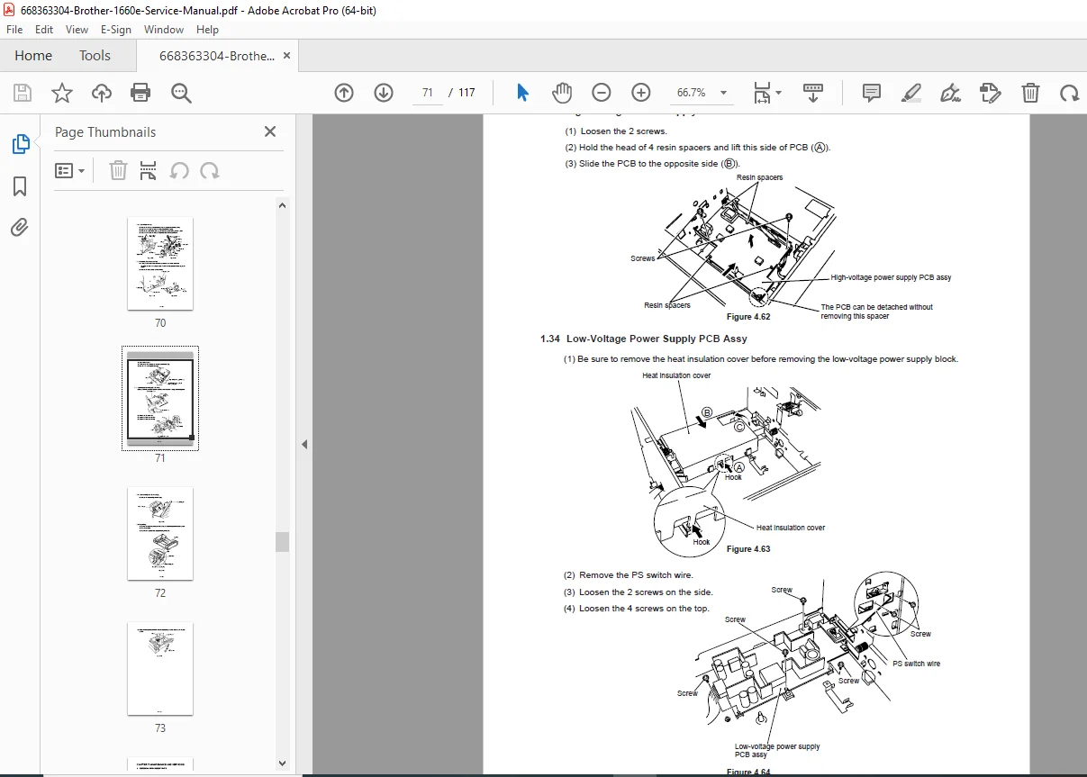
- Low-Voltage Power Supply PCB Assy (IV-24)
- Toner Cartridge (EP-ED Cartridge) (IV-25)
- Paper Tray (IV-25)
- Printer Disassembling Procedure Printer Body
- Chapter V: Maintenance and Servicing
- Periodical Replacement Parts (V-1)
- Consumable Parts Standard Endurance Table (V-1)
- List of Standard Tools (V-2)
- List of Lubricants and Cleaners (V-3)
- Chapter VI: Troubleshooting
- Introduction (VI-1)
- Initial Check (VI-1)
- Basic Procedure (VI-2)
- Test Printing and Mechanical Check (VI-2)
- Test Printing (VI-2)
- Image Defects (VI-3)
- Image Defect Examples (VI-3)
- Troubleshooting Image Defects (VI-4)
- Troubleshooting of Malfunctions (VI-11)
- Troubleshooting Paper Transport Problems (VI-19)
- Paper Jams (VI-19)
- Incomplete Paper Feed (VI-22)
- Operation (VI-23)
- Line Inspection Mode Procedure (VI-23)
- DRAM Test (VI-25)
- Status Message List (VI-26)
- Introduction (VI-1)
- Appendices
- Engine Block Diagram (A-1)
- Paper Feed/Size-SW PCB Circuitry Diagram (1/1) (A-2)
- Main PCB Circuitry Diagram (1/7 to 7/7) (A-3 to A-9)
- Control Panel PCB Circuitry Diagram (1/1) (A-10)
- Scanner LD PCB Circuitry Diagram (1/1) (A-11)
Effective Printable Area Table (Plain Paper, from Page I-9):
| Size | A (mm) | B (mm) | C (mm) | D (mm) | E (mm) |
|---|---|---|---|---|---|
| A4 | 210.0 | 297.0 | 203.2 | 288.5 | 3.39 ± 1.0 |
| Letter | 215.9 | 279.4 | 207.4 | 270.9 | 4.23 ± 1.0 |
| Legal | 215.9 | 355.6 | 207.4 | 347.1 | 4.23 ± 1.0 |
| Executive | 184.2 | 266.7 | 175.7 | 258.2 | 4.23 ± 1.0 |
| B6 (ISO) | 176.0 | 250.0 | 167.5 | 241.5 | 4.23 ± 1.0 |
| A6 | 148.0 | 210.0 | 139.5 | 201.5 | 4.23 ± 1.0 |
| B5 (ISO) | 176.0 | 250.0 | 167.5 | 241.5 | 4.23 ± 1.0 |
| A5 | 148.0 | 210.0 | 139.5 | 201.5 | 4.23 ± 1.0 |
Effective Printable Area Table (Envelope, from Page I-9):
| Size | A (mm) | B (mm) | C (mm) | D (mm) | E (mm) |
|---|---|---|---|---|---|
| COM-10 | 104.8 | 241.3 | 96.3 | 232.8 | 4.23 ± 1.0 |
| MONARCH | 98.4 | 190.5 | 89.9 | 182.0 | 4.23 ± 1.0 |
| DL | 110.1 | 221.0 | 101.6 | 212.5 | 4.23 ± 1.0 |
| B5 (ISO) | 176.0 | 250.0 | 167.5 | 241.5 | 4.23 ± 1.0 |
| C5 | 162.2 | 228.6 | 154.1 | 220.1 | 4.23 ± 1.0 |
This PDF manual for Brother HL-1660e laser printer equips you with expert knowledge from the Brother HL-1660e troubleshooting guide to resolve issues effectively.
Restore your printer’s peak performance—download this Brother HL-1660e service manual download instantly and handle repairs with professional precision!