
BT CBE Cargo 1.2-2.0 T/F Electric Forklift Service Manual PDF Download
Original price was: $39.95.$27.95Current price is: $27.95.
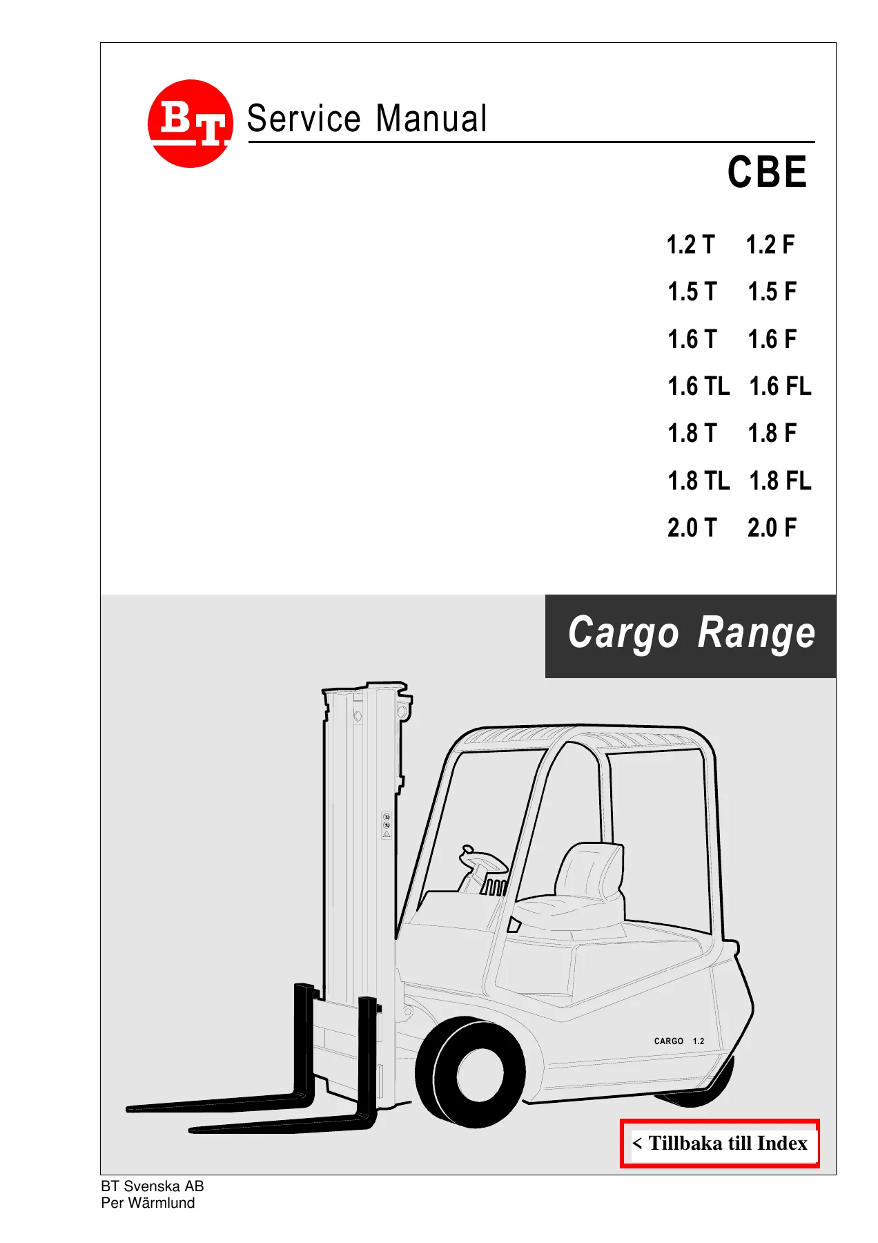
Complete BT CBE Cargo Range 1.2-2.0 T/F electric forklift service manual. Covers B1S traction and HP350 hydraulic controllers, Zapi console programming, wiring schematics, hydraulic diagrams, ZF/Hurt 502 transmission, brake system, torque values, and full maintenance schedules across all T and F variants.
Description
BT CBE Cargo 1.2-2.0 T/F Electric Forklift Service Manual
This is the complete workshop service manual for the BT CBE Cargo Range of electric counterbalance forklifts, covering every T and F variant from 1.2 to 2.0 tonnes. Published by BT Industries AB with content from CESAB S.p.A., it brings together the electrical, hydraulic and mechanical service information a technician needs to maintain, diagnose and repair these trucks. Controller parameters, wiring schematics, hydraulic circuit diagrams, transmission torque values and maintenance intervals are all reproduced from the original documentation in a single PDF.
File Details
- Manual type: Service Manual
- Brand: BT / CESAB
- Model: CBE Cargo Range 1.2-2.0 T/F
- Covered variants: 1.2 T, 1.2 F, 1.5 T, 1.5 F, 1.6 T, 1.6 F, 1.6 TL, 1.6 FL, 1.8 T, 1.8 F, 1.8 TL, 1.8 FL, 2.0 T, 2.0 F
- Language: English, Swedish, Italian, German, French, Spanish
- Page count: 108
- File format: PDF
Chapters Covered
- Electrical Section
- Mechanical Section
- Hydraulic Diagrams and System Schematics
- Wiring Diagrams
- Adjustment Tables
- Maintenance Schedules
Electrical Section — Controllers, Motors, Wiring and Diagnostics
The electrical section opens with the electronic panel characteristics for the B1S traction unit and HP350 lifting unit, both rated for a 48 V nominal supply (30–60 V variation) with 350 A maximum current and 18 kHz operating frequency. It documents the SCHABMULLER traction motor (V48, A108, 2160 RPM, 4.2 kW) and the SCHABMULLER lifting motor (V48, 1530 RPM, 9.5 kW driving a 17 L/min pump), including their service ratings and insulation class. Full wiring schematics follow for the auxiliary circuit, power circuit, and contactor connections of the B1S unit, alongside the potentiometer configuration for drive, steering and lifting — with resistance values, supply voltages, and expected output voltage ranges at specified angles.
The Zapi console chapter covers the keyboard layout (ROLL 1, ROLL 2, ENTER, OUT, PARAM, SET), the complete menu tree including Parameter Change, Tester, Save Param, Restore Param, Alarms, Program Vacc, and Steer Table. It explains how to read and clear the last five stored alarm codes with their timestamps, occurrence counts and panel temperature at the time of the fault, and how to program the accelerator max stroke. The diagnostic LED flash-code tables for both the B1S and HP350 units are reproduced in full — from 1 flash (EEPROM/watchdog) through 9 flashes (contactor closed), plus continuous flashing for battery discharge and fixed LED for double running requests. Each code is paired with the components to check and the corrective action.
The adjustment tables for the B1S traction unit and HP350 lifting unit list every programmable parameter across ten levels — Traction I MAX (175–350 A), Acceleration (1.2–4 sec), Cutback Speed (20–100% V Batt), Invers Braking (15–45% I MAX), Release Braking, Pedal Braking, Weak Dropout, Creep Speed, Plug Current, Braking Modulation, Compensation, and the HP350 equivalents for acceleration delay, deceleration delay, I MAX (200–400 A or 175–350 A), Speed Coarse/Fine, Compensation, Hydro Time, Min/Max Valve Volt and the multi-stage tilt and sideshift speed adjustments. The dashboard layout and its 15 indicator lamps — battery status, parking brake, motor temperatures, brush wear, hour meter, deadman, diagnostics — are also documented.
Mechanical Section — Transmission, Drive Unit and Brakes
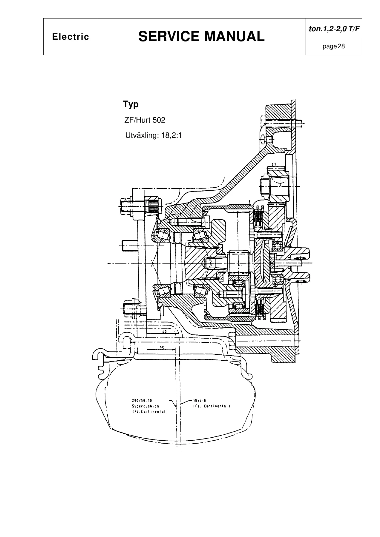
The mechanical portion centers on the ZF/Hurt 502 transmission with its 18.2:1 gear ratio. A cutaway drawing of the drive unit shows the complete assembly including the motor, gearbox, brake cylinder and wheel hub. Oil fill and drain plug locations are identified with a 0.22 litre capacity for the first change at 80 hours and every 1000 hours thereafter. Wheel mounting torques (14 daNM drive wheels, 18 daNM steered wheels), drive unit securing torques (13.5 daNM to frame, 2.3 daNM electric motor, 5.5 daNM brake delivery tubing), and parking brake cable fixing (5 daNM) are all tabulated. The brake cylinder removal procedure describes the three motor retaining screws, the longer screw insertion into the upper hole, and the 2 cm motor shift needed to access the cylinder retaining pin. Brake system bleeding, brake fluid level checks, and the 60 kg pedal force / 40 mm pedal travel specification for the service brake are also covered.
Hydraulic Diagrams and System Schematics
Hydraulic circuit diagrams for both the T and F variants show the complete oil flow paths from the pump through the control valve, lift cylinders, tilt cylinders and auxiliary functions. The load sensor, priority valve, main relief setting (180–220 bar), and the 0.7 mm flow limiter for tilt forward are identified. A separate schematic covers the mast lifting circuit with the pressure valve (0.5 bar) and the 90 bar test point. The hydraulic panel connections for the HP350 are documented at pin level, covering the lift potentiometer, microswitches for lift, aux 1, aux 2, tilt, aux 3, forward and backward, and the Zapi instrument interface.
Wiring Diagrams
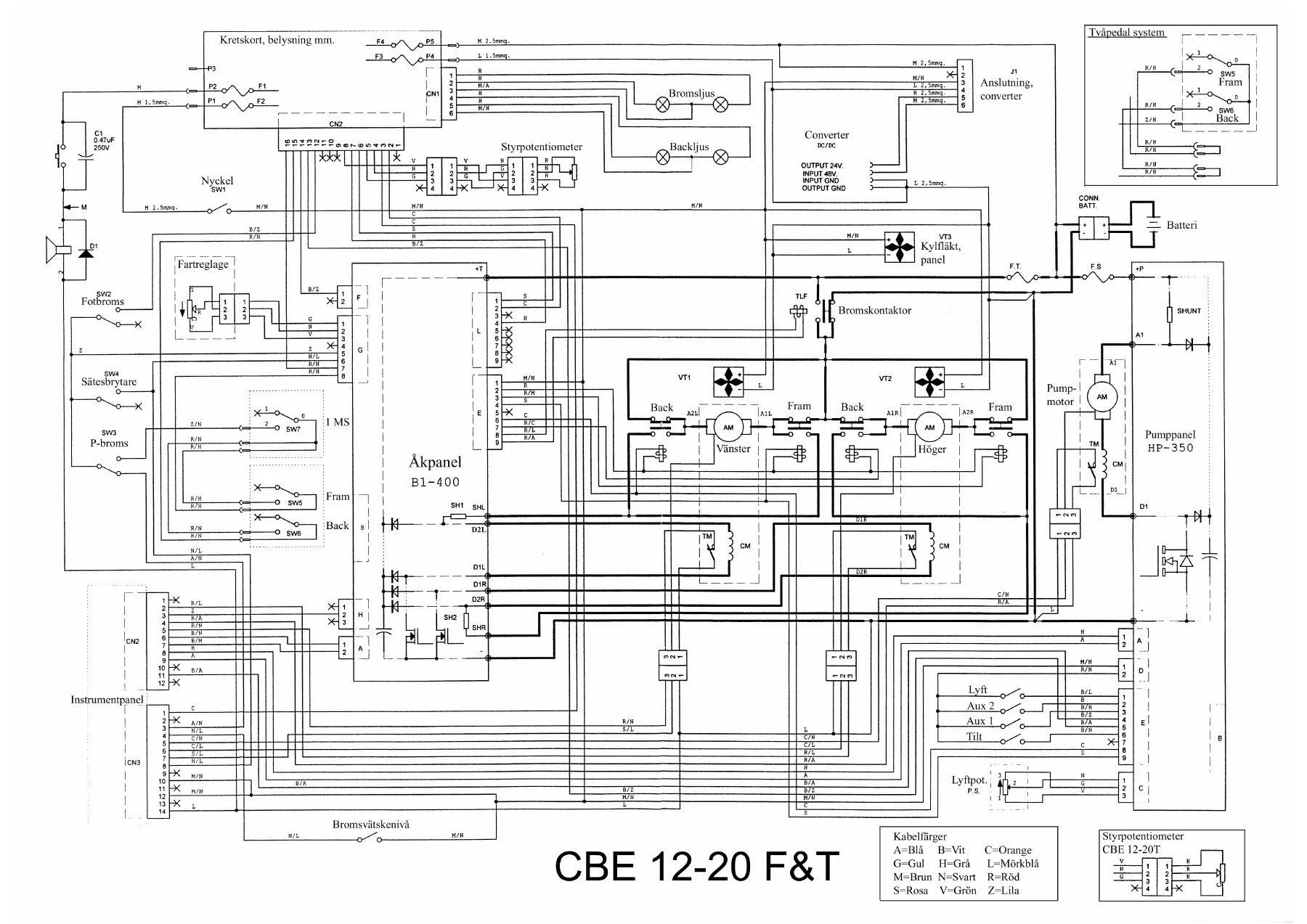
Full-colour wiring diagrams for the CBE 12-20 F&T show the complete 48 V traction circuit — battery, main fuse, shunt, key switch, direction contactors (TIS, TAS, TID, TAD), brake contactor (TFR), drive motors, field windings, freewheeling diodes, brake diodes, and the B1S power module. Separate diagrams cover the lighting extra card (brake lights, reverse lights), the DC/DC converter for 24 V output, the steering potentiometer, the lift potentiometer, and the instrument panel connectors (CN2 and CN3). The diagrams are reproduced with the original colour coding and a legend for wire colours (orange, blue, white, dark blue, yellow, grey, brown, black, pink, red, green, purple).
Maintenance Schedules and Appendices
Maintenance intervals are laid out at 8, 50, 250, 500, 1000, 2000, 4000 and 10000 hours for medium/intense use, with a separate column for occasional use expressed in days or months. Items include mast guide pads, carriage and sideshift unit pads, mast rollers and chain rollers, fork positioning pins, lifting oil filter, lifting system oil, mast guides, retaining collars, transmission oil, brake fluid, steering system seals, wheel hub bearings, parking brake pedal, service brake pedal, flexible brake hoses, electronic control, contactors, and safety circuit checks. The appendices list oil and grease specifications (AGIP ARNICA 46, AGIP ATF IID, AGIP BRAKE FLUID DOT 4, MOBILGREASE SPECIAL, MOBILTEMP SHC 100, AGIP ARNICA 22), tire pressures (front and rear), and the full symbol legend used throughout the manual in Italian, English and German.
What This BT CBE Cargo Service Manual Enables You to Do
With this manual on hand, you can read and clear controller fault codes, adjust acceleration and braking parameters through the Zapi console, diagnose VMN and contactor faults from the LED flash sequences, trace a no-run condition through the start sequence logic, test potentiometer signals in real time, and replace a transmission, brake cylinder or hydraulic pump with the correct torque figures. The wiring diagrams — covering the complete 48 V traction circuit, lighting, steering potentiometer and hydraulic panel — turn hours of electrical guesswork into a systematic fault-finding process.
For workshops maintaining a mixed fleet of 1.2 T through 2.0 T CBE Cargo trucks, having the exact parameter tables, diagnostic codes and hydraulic schematics in one PDF eliminates the risk of applying the wrong specification to the wrong variant. The B1S and HP350 adjustment tables alone map every parameter from Traction I MAX to Min Valve Volt across all ten programmable levels, making controller setup and troubleshooting far more precise.
IMAGES PREVIEW
Delivered as an instant PDF download. No shipping, no waiting. Open it on any laptop, tablet or phone in the workshop, print the pages you need for the job, and keep the full manual on file for the next truck that rolls in. Once payment clears, the download link is immediately available.
Reviews
There are no reviews yet.