
BT LWE140 LWE160 LWE180 LWE200 LWE250 Pallet Truck Repair Manual – PDF Workshop Download
Original price was: $32.95.$19.95Current price is: $19.95.
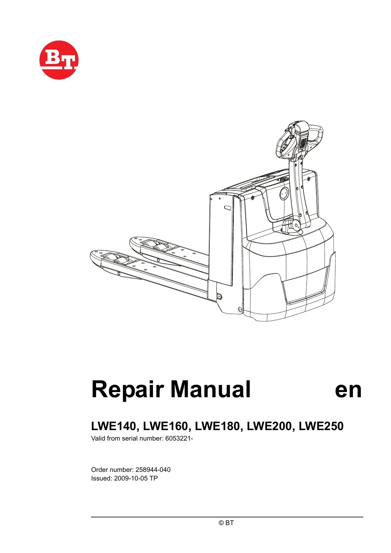
Complete 190-page BT repair manual for LWE140, LWE160, LWE180, LWE200 and LWE250 electric pallet trucks. Covers installation, maintenance, parameters, error codes, hydraulics, electrical system, tiller arm, brake, gear and wheels. Order number 258944-040, valid from serial 6053221-.
Description
BT LWE140, LWE160, LWE180, LWE200 and LWE250 Repair Manual
This is the full BT workshop repair manual for the LWE140, LWE160, LWE180, LWE200 and LWE250 electric pallet truck range, published under order number 258944-040 and valid from serial number 6053221-. Across 190 pages it documents everything from first-time battery installation and PIN-code programming through to stripping the drive unit off the fork frame, replacing the tiller arm safety sensor and reading fault codes out of the truck’s control system. If you service, repair or maintain one of these trucks, this is the reference the work should be done against.
File Details
- Manual type: Repair / workshop manual
- Brand: BT
- Models covered: LWE140, LWE160, LWE180, LWE200, LWE250
- T-codes: 838, 839, 840
- Valid from serial number: 6053221-
- Order number: 258944-040
- Issued: 2009-10-05
- Language: English
- Page count: 190
- Format: PDF
Chapters Covered
- General introduction – how to use the manual, warning symbols, pictograms for screws and nuts
- General safety rules – safety while working, electrical system precautions, safe lifting and support
- Installation – battery installation and safety, programming PIN codes, setting the parameters, function and safety check
- Maintenance – service intervals and the 750 h / 12 month maintenance chart
- Functions and parameters – principle functions, timer, driver parameters, service parameters, factory parameters
- Troubleshooting – error code history and error code system, error codes, troubleshooting diagrams, built-in test functions, status of digital inputs and outputs, display test function
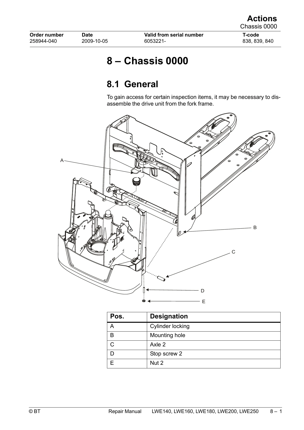
- Chassis 0000 – disassembling the drive unit from the fork frame, removing the platform, castor cradle damper and springs
- Fork frame 0380 – component breakdown
- Electrical drive motor 1700 – removing the motor, fitting the temperature sensor, tightening torques, cleaning
- Drive unit / gear 2550 – general and removing the gear from the truck
- Brake 3180 – components and manual brake release
- Drive wheel 3530 – changing the drive wheel
- Castor wheel 3540 – components, mounting, changing the wheel, the cradle and the springs
- Fork wheel 3550 – climber wheel and support arm wheel
- Tiller arm 4000 – removing the tiller arm, gas suspension, safety sensor, tiller arm handle, logic card, signal button, raising/lowering buttons, push buttons, lifting control lever, safety reversing switch
- Electrical components – changing the wiring harness, replacing the transistor regulator, lift height limit sensor [B61]
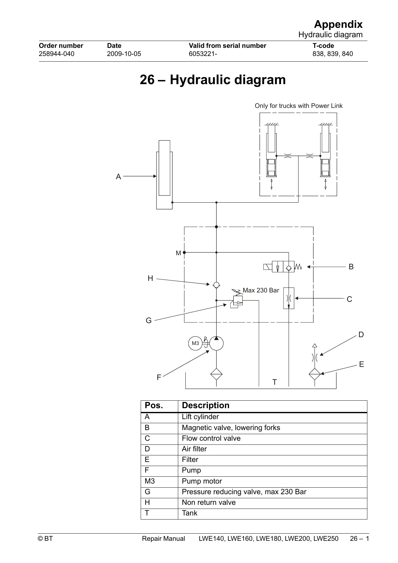
- Hydraulic system 6000 – hygiene rules, components, tube connections, quick-change connectors, pressure-limiting valve, removing the hydraulic unit, tightening torques
- Accessories – Spider expansion unit, TLS, ID unit, T.W.I.S., integrated battery charger
- Appendix and general tightening torques
- Tools – MQS, AMP and Molex connectors, grease guns
- Oil and grease specification – lubricant table and lubrication schedule
- Electrical components and electrical diagram – symbol index, overview diagram, wiring diagram
- Hydraulic diagram
- Destruction instructions – material marking, pressure vessels, sorting categories
What makes this document genuinely useful is that it does not stop at the mechanical side. The parameter chapter explains how the truck’s control system is configured, how driver, service and factory parameters are read and entered from the keypad, and how the battery and battery charger settings are matched to the battery actually fitted. The troubleshooting chapter then ties that configuration back to the fault codes the truck displays, so a symptom on the display can be traced to a specific sensor, cable, contactor or regulator output. Alongside that sit the conventional repair procedures – separating the drive unit from the fork frame, pulling the motor and gear, releasing the brake manually, changing the drive, castor and fork wheels, and rebuilding the tiller arm handle down to individual buttons and switches.
Troubleshooting and Error Code Diagnostics
A large part of the manual is devoted to the truck’s electronic control system. It explains the structure of the error codes – group, error category and error code – and lists the individual codes with the event they produce, the possible cause and the measure to take. Codes are grouped by system: transistor regulator and logic card, drive system, hydraulic system and options. Separate troubleshooting diagrams walk through the common complaints, including a truck that cannot be driven at all, a truck that only drives at reduced speed, a truck that drives but behaves abnormally, and faulty hydraulic functions. Built-in test functions are documented with the display segments that light for each digital input and output, so the transistor regulator, logic card and expansion unit can be checked without guessing.
Hydraulics, Electrical and Mechanical Repair
The hydraulic chapter sets out the cleanliness rules that have to be observed when opening the system, shows the hydraulic unit components for the LWE140/160/180 and for the LWE200/250, and gives the procedure for adjusting the pressure-limiting valve, removing the hydraulic unit and splitting the tank from the motor. The electrical chapter covers the wiring harness and the contacts to the transistor regulator, replacement of the regulator itself, and the lift height limit sensor including how to adjust it. Mechanical coverage spans the chassis, fork frame, drive motor, drive gear, brake, drive wheel, castor wheel, fork wheel and tiller arm, with exploded component views throughout. Technical data at the back of the book gives drive motor output, brake braking force and nominal play, gear oil volume and type, wheel dimensions and axle pressures, hydraulic pressures and pump flow, fuse ratings, battery compartment weights, travel and lift speeds, and incline climbing ability.
Get the Complete BT LWE Repair Manual
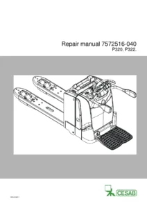
IMAGES PREVIEW
With this BT LWE140, LWE160, LWE180, LWE200 and LWE250 repair manual on hand you can carry out scheduled 750-hour services, diagnose fault codes instead of swapping parts, set parameters correctly after a battery change, release and service the brake, replace worn wheels and castors, rebuild the tiller arm, and repair or replace the drive motor, gear and hydraulic unit to the manufacturer’s own procedures and torque figures. Working from the correct specification matters on equipment like this – an incorrectly adjusted pressure-limiting valve, a wrongly set battery parameter or an uncalibrated lift height sensor all lead to repeat failures and unnecessary cost. The manual is delivered as an instant PDF download after payment, with no shipping and no waiting, and it can be stored on a laptop, tablet or phone and printed for use in the workshop.
Reviews
There are no reviews yet.