★ TRUSTED BY 321,897+ PROFESSIONALS WORLDWIDE
🏒
Trusted Business
Verified & Licensed
πŸ›‘οΈ
Virus Free Files
100% Safe Downloads
πŸ”’
Secure Payment
SSL Protected
⚑
Instant Delivery
Available Immediately
Sale!

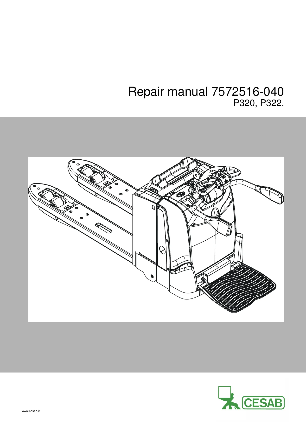
Cesab P320 P322 Repair Manual – 7572516-040 Electric Pallet Truck Workshop PDF

Original price was: $39.95.Current price is: $23.95.

Complete 578-page Cesab P320 P322 repair manual, publication 7572516-040, valid from serial 6304531-. Full workshop coverage of chassis, drive gear, brakes, steering, electrical, hydraulics and options with wiring and hydraulic schematics.

⚑
Instant PDF Download
Available immediately
πŸ’Ύ
Save to Your Device
Download & keep forever
πŸ›‘οΈ
Antivirus Scanned
100% virus-free
🌍
Trusted Worldwide
175,000+ customers

Description

Cesab P320 P322 Repair Manual – Complete Workshop Documentation for the Electric Pallet Truck

This is the full Cesab repair manual for the P320 and P322 electric pallet trucks, published under document number 7572516-040 and valid from serial number 6304531 onward. At 578 pages, it is the complete service reference for these machines, covering every major system from the chassis and drive unit through to the hydraulics, electrical system, steering and brakes. Whether you maintain a fleet of P320/P322 trucks or own a single unit, this Cesab P320 P322 repair manual gives you the manufacturer’s own procedures for diagnosis, repair, adjustment and calibration.

File Details

  • Manual type: Repair manual (workshop service documentation)
  • Brand: Cesab
  • Models covered: P320, P322
  • T-Code: 1010
  • Publication number: 7572516-040
  • Valid from serial number: 6304531-
  • Language: English
  • Page count: 578 pages
  • File format: PDF
  • Revision history: 2014-08-11 (completely new issue), 2015-03-01 (parameters 111, 211 and 1061 updated; Chapter 9 suspension tables revised), 2015-10-01 (Chapter 9 Chassis and Chapter 13 Steering system updated)

Chapters Covered

  • General introduction – how to use the manual, warning levels and symbols, pictograms
  • General safety rules – work safety, electrical systems, safe lifting, truck modifications
  • Operation and connection sequences – battery connection, login via keypad, tiller arm driving positions, driving in fork and drive wheel direction, neutral position braking, reverse braking, mechanical braking, emergency reversal, fork lifting and lowering
  • Parameters – general parameters, operator parameters, general service parameters, travel function service parameters, hydraulic function service parameters, factory parameters, calibration parameters and full calibration procedures
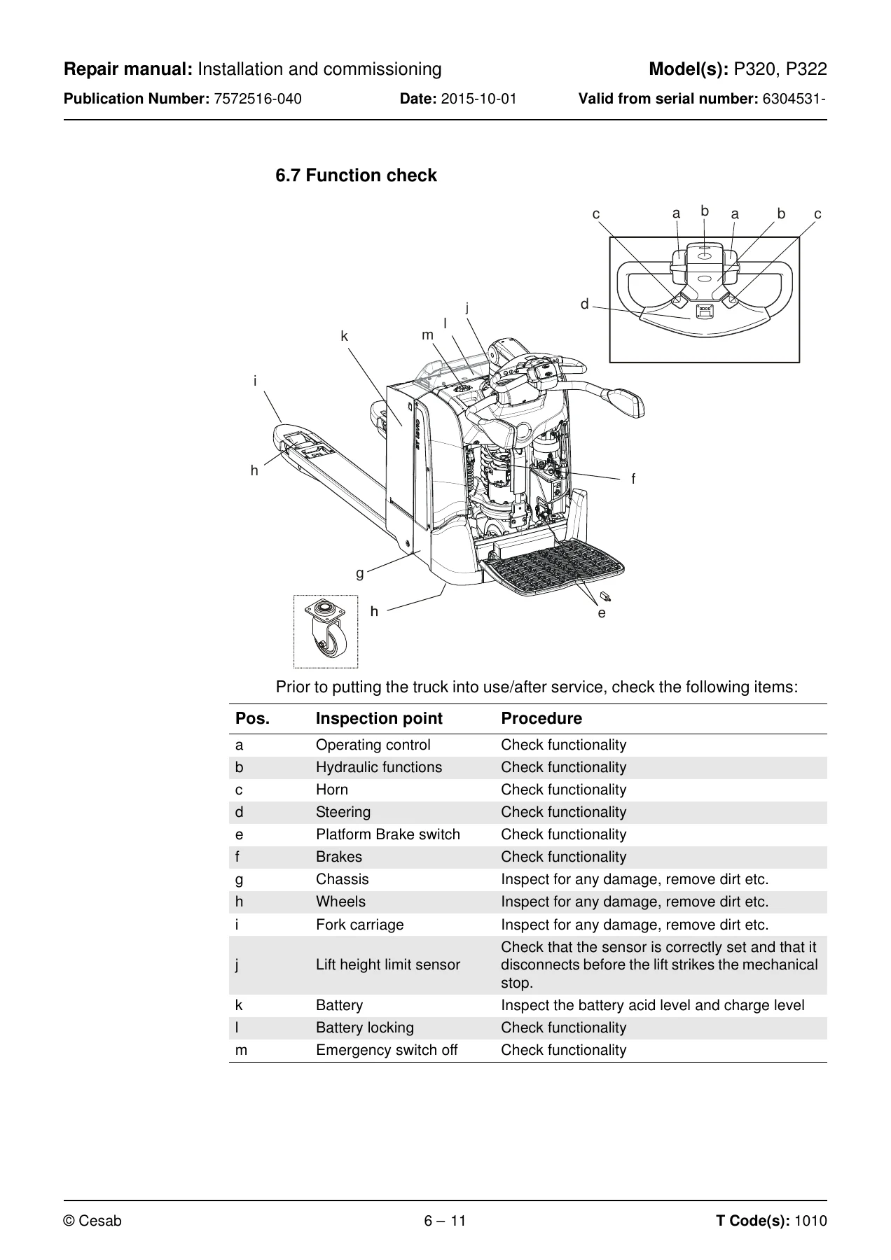
  • Installation and commissioning – transporting the truck and fork carriage, lifting methods, battery installation, PIN codes, setting parameters, function check
  • Maintenance – cleaning and washing, oil and grease specifications, periodic maintenance schedule with 1000-hour and 3000-hour intervals
  • Troubleshooting – towing a defective truck, emergency driving mode, error code history, error code system, full error code listing, service information, digital input/output test modes, built-in tiller arm test function
  • Chassis C0000 – hatches and covers, fork frame, battery compartment parts, drive unit suspension, platform, operator protection, signs and labels
  • Motors C1000 – electric pump motor, steering motor, motor control fans, drive motor (1.8/2.5 kW and 2.8 kW variants)
  • Transmission/Drive gear C2000 – small and large gear, replacing the drive gear, oil check and oil change, steering bearing, studs, wheel hub seal
  • Brake system/Wheels C3000 – brake system, parking brake, drive wheel, castor wheel, fork wheels, wheel wear limits
  • Steering system C4000 – steering arm, tiller arm, E-man tiller arm, power steering, steering angle sensor, mechanical steering
  • Electrical system C5000 – menus, battery, electric panel, motor control, horn, control system, fuses, sending units and sensors, safety sensors
  • Hydraulic system C6000 – hydraulic hygiene, hydraulic unit, tank, valve unit, hydraulic pump, return filter, valve coil, flow control valve, pressure limitation, lift cylinders, quick change connectors
  • Mast C7000
  • Peripherals C8000
  • Options/Extra equipment C9000 – Spider expansion unit, I_Site, DC/DC converter, collision sensor, integrated battery charger, E-bar, fire extinguisher
  • Instructions for disposal – marking of plastics, pressure vessels, sorting categories
  • Electrical components and wiring diagrams – component tables, component location photographs, wiring diagrams for standard and fixed platform plus accessories
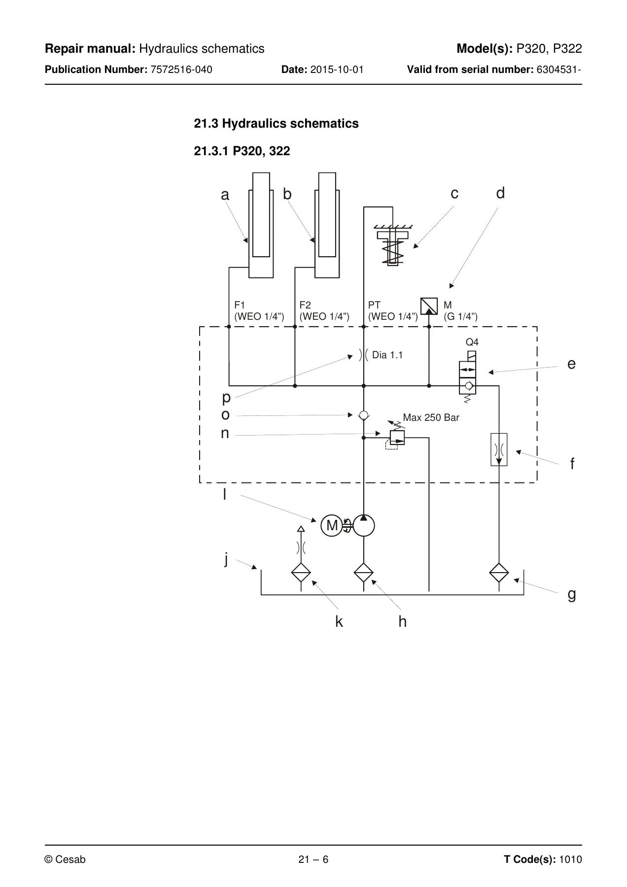
  • Hydraulics schematics – component list, component location, valve unit, hydraulic schematics for P320 and P322
  • Tools – AMP, MQS and CPC contacts, service instruments, hydraulic pressure gauges
  • Service data and grease specifications – general tightening torques, oil and grease specifications
  • Technical data – basic data, dimensions, weights, performance, battery data, service data

What this Cesab P320 P322 repair manual gives a technician is the complete system-by-system service picture in one document. Chapter 4 walks through every operating sequence and the electrical conditions that trigger it. Chapter 5 gives the full parameter architecture across operator, service, factory and calibration levels. Chapter 8 turns the truck’s own error-code system into a diagnostic tool with the truck behaviour, error cause and step-by-step remedy for each code. Chapters 9 through 15 then break the machine into serviceable assemblies, and Chapters 20 through 23 give the wiring, hydraulic schematics, special tools and service data needed to finish the job properly.

How the Manual Is Organised

Cesab structures the service content around a C-code system, and this repair manual follows it. The chassis is C0000, motors C1000, transmission and drive gear C2000, brake system and wheels C3000, steering C4000, electrical system C5000, hydraulic system C6000, mast C7000, peripherals C8000 and options C9000. Each C-code chapter opens with an overview illustration keyed to numbered components, followed by the replacement, checking, adjusting and calibration procedures for that assembly. This is why the document works as a bench reference: you can go directly to the system you are working on and follow the sequence from removal through refitting without hunting across the file.

Procedures and Diagnostics Included

The Cesab P320 P322 service manual covers the practical jobs that actually come up in a workshop. On the chassis side you get fork carriage replacement, torsion tube linkage and wheel fork work, drive unit suspension replacement with and without servo, spring force relieving and tensioning using the special tool, platform replacement, gas spring replacement, gate assembly work, pad and gate bar replacement, and inductive position sensor replacement. On the drive side there is drive gear removal and refitting, oil check and change for both small and large gear, steering bearing replacement, wheel hub seal replacement and stud replacement. The brake section covers parking brake gap checking and adjustment, emergency release, friction disc replacement, brake hub replacement and cleaning. Steering work covers tiller arm replacement, steering yoke, steering damper, steering angle sensor, steering bearing and mechanical stop procedures for both power steering and mechanical steering variants. The hydraulic chapter covers the hydraulic unit, tank, valve unit, hydraulic pump, return filter, valve coil, flow control valve, pressure limiting valve adjustment, pressure sensor and lift cylinders, along with quick change connector assembly and dismantling.

Electrical and Hydraulic Reference Material

Beyond the procedures, this Cesab P320 P322 repair manual carries the reference material that makes fault-finding and repair verification possible. Chapter 20 lists every electrical component with its designation, function and component type, followed by component location photographs and full wiring diagrams for both the standard platform and the fixed platform, plus the accessories diagram covering the DC/DC converter, on-board charger, collision sensor, DHU and Li-ion battery. Chapter 21 provides the hydraulic component list, component location images and the P320/P322 hydraulic schematic with the valve unit detail. Chapter 23 gives general tightening torques across strength classes 8.8, 10.9 and 12.9 for M3 through M24, and the oil and grease specification tables by ambient temperature and application. Chapter 24 closes with technical data on dimensions, weights, performance, battery and service data.

Error Codes and Troubleshooting

The troubleshooting chapter is a genuine working tool rather than a list of codes. Each entry shows the code, the description, the truck behaviour, the possible error cause and the procedure to follow. Error groups are organised by system: group 2 for the main control unit A5, group 3 for the drive system, group 4 for the hydraulic system, group 5 for the steering system and group 8 for options. The manual also explains the extended error log, the CAN bus resistance checks, the digital input/output test modes and the built-in tiller arm test function so you can confirm a fault before you replace a component.

Parameters and Calibration

Parameter work is covered in full detail. Operator parameters 1 to 7, general service parameters 101 to 112, travel function service parameters 201 to 253, hydraulic function parameters, factory parameters 1001 to 1117 and calibration parameters 1251 to 1272 are all described with their minimum, default, maximum, increment and unit values. The calibration procedures themselves – steering angle calibration, weight measuring calibration 3 and weight measuring calibration 6 – are documented step by step. The factory parameter section also explains the configurable optional functions 1003 to 1042 and how they activate SEU outputs, option buttons and truck movements.

Complete PDF Bookmark Tree

Complete Bookmarks

The complete bookmarks in the β€œCesab P320 P322 Repair Manual – 7572516-040 Electric Pallet Truck Workshop PDF” are as follows:

1. Contentsp. 3
2. General introductionp. 13
2.1 How to use this manualp. 13
2.2 Warning levels and symbolsp. 14
2.3 Pictogramsp. 15
3. General safety rulesp. 17
3.1 Work safetyp. 17
3.2 Electrical systemsp. 19
3.3 Safe liftingp. 20
3.4 Truck modificationsp. 21
4. Operation and connection sequencesp. 23
Symbols on keypad and displayp. 24
4.1 Battery is connectedp. 25
4.2 Login via keypadp. 25
4.3 Tiller arm lowered for drivingp. 26
4.4 Driving in fork directionp. 26
4.5 Driving in the drive wheel directionp. 27
4.6 Neutral position brakingp. 27
4.7 Reverse brakingp. 28
4.8 Mechanical brakingp. 28
4.9 Emergency reversalp. 29
4.10 Fork liftingp. 29
4.11 Fork loweringp. 30
5. Parametersp. 31
5.1 General parametersp. 31
5.1.1 Show/change parametersp. 32
5.2 Operator parametersp. 33
5.2.1 Overviewp. 33
5.2.2 Connection to logged-in operatorp. 34
Description of operator parametersp. 34
Parameters 1, 2, 5, 6 and 7 – Maximum travel speedp. 34
Parameters 3 and 4 – Acceleration/Decelerationp. 36
5.3 General service parametersp. 37
5.3.1 Overviewp. 37
5.3.2 Descriptionp. 38
Parameter 101/104 – Service/Log-outp. 38
Verifying parameter settings for freely ventilated batteries (lead-acid batteries)p. 43
Verifying the parameter setting for valve-regulated batteries (Exide)p. 43
5.4 Service parameters, travel functionsp. 47
5.4.1 Overviewp. 47
5.4.2 Descriptionp. 48
5.5 Service parameters, hydraulic functionsp. 57
5.5.1 Descriptionp. 58
5.6 Factory parametersp. 59
5.6.1 Overviewp. 59
5.6.2 Descriptionp. 60
Factory parameters # 1003 to 1042 – configurable optional functionsp. 63
5.7 Calibration parametersp. 85
5.7.1 Overviewp. 85
5.8 Calibrationp. 88
5.8.1 Steering angle calibration β€œ1”p. 89
5.8.2 Calibration β€œ2” (Not applicable)p. 89
5.8.3 Calibration of weight measuring "3"p. 90
5.8.4 Calibration β€œ4” (Not applicable)p. 90
5.8.5 Calibration β€œ5” (Not applicable)p. 90
5.8.6 Calibration of weight measuring "6"p. 91
6. Installation and commissioningp. 93
6.1 Transporting the truckp. 93
6.2 Transporting the fork carriagep. 93
6.3 Lifting the truckp. 94
6.3.1 Lift using an eye boltp. 94
6.3.2 Lift using a jackp. 95
6.4 Battery installationp. 96
6.4.1 Safety for battery handlingp. 96
6.4.2 Installing the batteryp. 97
6.5 Using PIN codesp. 98
6.5.1 Generalp. 98
6.5.2 PIN code for resetting after a collisionp. 98
6.5.3 Programming PIN codesp. 99
6.5.4 PIN code defaultsp. 101
6.6 Setting parametersp. 102
6.6.1 Setting collision sensor parameters (option)p. 102
6.6.2 Setting battery parametersp. 102
6.7 Function checkp. 103
7. Maintenancep. 105
7.1 Introductionp. 105
7.2 Maintenance instructionsp. 105
7.2.1 Cleaning and washingp. 105
7.2.2 High-pressure washersp. 106
7.2.3 Degreasing agentsp. 106
7.2.4 Cleaning the exteriorp. 106
7.2.5 Cleaning the chainp. 107
7.2.6 Cleaning the motor compartmentp. 107
7.2.7 Electric componentsp. 107
7.3 Oil and grease specificationp. 108
7.4 Symbolsp. 109
7.5 Periodic maintenancep. 111
8. Troubleshootingp. 131
8.1 Towing a defective truckp. 131
Tow using a tow truck and tow wagon:p. 131
8.2 Auxiliary functionsp. 132
8.2.1 Emergency driving modep. 132
8.3 Error code historyp. 133
8.3.1 Extended error logp. 134
8.4 Error code systemp. 135
8.5 Error codesp. 136
8.6 Service informationp. 207
8.7 Digital input/output statusp. 209
8.7.1 Test mode β€œ9” –p. 209
8.7.2 Test mode β€œ12” – Expansion unit SEU (option).p. 210
8.8 Built-in test function for the tiller armp. 211
8.8.1 Display testp. 211
8.8.2 Speed controlp. 211
8.8.3 Safety reversingp. 211
8.8.4 Controls for lifting/loweringp. 211
8.8.5 Sensiliftp. 212
8.8.6 Keypadp. 212
9. Chassis C0000p. 213
9.0.1 Overviewp. 213
9.1 Hatches, covers C0340p. 214
9.1.1 Overviewp. 214
9.1.2 Replacing the service coverp. 215
Removing the service coverp. 215
Fitting the service coverp. 215
9.1.3 Replacing the side coverp. 216
Removing the side coverp. 216
Fitting the side coverp. 216
9.1.4 Replacing the cover (without gate)p. 217
Removing the cover (without gate)p. 217
Fitting the cover (without gate)p. 217
9.1.5 Replacing the gate coverp. 218
Remove the gate coverp. 218
Fitting the gate coverp. 218
9.1.6 Replacing the emblem coverp. 219
Removing the emblem coverp. 219
Fitting the emblem coverp. 219
9.1.7 Replacing the upper coverp. 220
Removing the upper coverp. 220
Fitting the upper coverp. 220
9.1.8 Replacing the steering adapter coverp. 221
Removing the steering adapter coverp. 221
Fitting the steering adapter coverp. 221
9.1.9 Replacing the rubber sealsp. 222
Removing the rubber sealsp. 222
Fitting the rubber sealsp. 223
9.2 Fork frame C0380p. 225
9.2.1 Overview fork framep. 225
9.2.2 Replacing the fork carriagep. 226
Removing the fork carriagep. 226
Fitting the fork carriagep. 228
9.2.3 Checking the fork carriagep. 229
9.2.4 Replacing the torsion tube-linkage-wheel forkp. 230
Removing the torsion tube-linkage-wheel forkp. 230
Fitting the torsion tube-linkage-wheel forkp. 233
9.2.5 Checking the torsion tube-linkage-wheel forkp. 235
9.2.6 Replacing the roller on the torsion tubep. 236
Removing the roller on the torsion tubep. 236
Fit the roller on the torsion tubep. 236
9.2.7 Weld the push rodp. 237
9.3 Battery compartment parts C0390p. 241
9.3.1 Battery lock, fixedp. 241
Overviewp. 241
Descriptionp. 241
9.3.2 Battery lock, quickp. 242
Overviewp. 242
Descriptionp. 242
9.4 Drive unit suspension C0450p. 243
9.4.1 Overviewp. 243
Table showing suspension/PT cylinder mechanical steeringp. 244
9.4.2 Overview,p. 245
Table showing suspension/PT cylinder power steeringp. 246
Table showing suspension/PT cylinder mechanical steeringp. 246
Descriptionp. 247
9.4.3 Replacing the drive unit suspensionp. 248
Removing the small drive unit suspensionp. 248
Fitting the small drive unit suspensionp. 251
Removing the large drive unit suspensionp. 254
Fitting the large drive unit suspensionp. 257
9.4.4 Relieving spring force using the special toolp. 260
9.4.5 Tensioning spring force using the special toolp. 262
9.4.6 Adjusting the tool.p. 263
9.4.7 Replacing the initial pressure springp. 264
Removing the initial pressure springp. 264
Fitting the initial pressure springp. 264
9.4.8 Replacing the PowerTrak springp. 265
Removing the PowerTrak springp. 265
Fitting the PowerTrak springp. 265
9.4.9 Replacing the PowerTrak cylinderp. 266
Removing the PowerTrak cylinderp. 266
Fitting the PowerTrak cylinderp. 266
9.5 Platform including fixing points C0560p. 267
9.5.1 Overview, Standard and Cold storep. 267
9.5.2 Overview, platformp. 268
9.5.3 Replacing the platformp. 269
Removing the platformp. 269
Fitting the platformp. 271
9.5.4 Replacing the gas springp. 273
Removing the gas springp. 273
Fitting the gas springp. 275
9.5.5 Checking the gas springp. 275
9.5.6 Replacing the springp. 276
Removing the platform suspensionp. 276
Fitting the platform suspensionp. 277
9.5.7 Adjusting platform suspensionp. 277
9.5.8 Replacing the platform inductive position sensorp. 278
Removing the platform inductive position sensor (B119)p. 278
Fitting the platform inductive position sensor (B119)p. 278
Removing the lower platform inductive position sensor (B120)p. 279
Fitting the lower platform inductive position sensor (B120)p. 279
9.5.9 Checking the position sensor (B120), std platformp. 280
9.5.10 Adjusting the presence sensorp. 280
9.5.11 Fixed side guardp. 281
9.5.12 Overviewp. 281
9.5.13 Replacing the fixed side guardp. 282
Removing the fixed side guardp. 282
Fitting the side guardp. 283
9.5.14 Photo cells, fixed side guardp. 284
Overview, positioningp. 284
9.5.15 Overview, platform with fixed side guardp. 285
9.5.16 Replacing a platform with fixed side guardp. 286
Removing a platform with fixed side guardp. 286
Fitting a platform with fixed side guardp. 286
9.5.17 Checking the position sensor (B120), fixed side guardsp. 287
9.5.18 Adjusting the presence sensorp. 287
9.5.19 Adjusting platform suspensionp. 288
9.5.20 Back guardp. 289
9.5.21 Overviewp. 289
9.5.22 Replacing the back guardp. 290
Removing the back guardp. 290
Fitting the back guardp. 290
9.5.23 Checking the position sensor (B120), back guardp. 291
9.5.24 Adjusting the presence sensorp. 291
9.5.25 Adjusting platform suspensionp. 292
9.6 Operator protection C0840p. 293
9.6.1 Gatep. 293
Overviewp. 293
9.6.2 Replacing the gatep. 294
Removing the gate assemblyp. 294
Fitting the gate assemblyp. 295
9.6.3 Replacing the gate damperp. 296
Removing the gate damperp. 296
Fitting the gate damperp. 296
9.6.4 Replacing the gate damperp. 297
Removing the gate damperp. 297
Fitting the gate damperp. 297
9.6.5 Replacing the padp. 298
Removing the padp. 298
Fitting the padp. 299
9.6.6 Replacing the gate barp. 300
Removing the gate barp. 300
Fitting the gate barp. 300
9.6.7 Checking the gate barp. 300
9.6.8 Replacing the upper inductive position sensorp. 301
Removing the upper inductive position sensorp. 301
Fitting the upper inductive position sensorp. 301
9.6.9 Checking the upper inductive position sensor B121p. 301
9.6.10 Replacing the lower inductive position sensorp. 302
Removing the lower inductive position sensorp. 302
Fitting the lower inductive position sensorp. 302
9.6.11 Checking the lower inductive position sensor B122p. 302
9.7 Signs, warnings, labels C0850p. 303
10. Motors C1000p. 305
10.1 Electric pump motor C1710p. 305
10.1.1 Overviewp. 305
10.1.2 Replacing the pump motorp. 307
Removing the pump motorp. 307
Fitting the pump motorp. 308
10.1.3 Replacing the carbon brushesp. 309
Removing the carbon brushesp. 309
Fitting the carbon brushesp. 310
10.2 Steering motor C1730p. 311
10.2.1 Overviewp. 311
10.2.2 Replacing the steering motorp. 313
Removing the steering motorp. 313
Fitting the steering motorp. 313
10.3 Motor control fansp. 314
10.3.1 Overviewp. 314
10.3.2 Replacing the motor control fansp. 315
Removing the motor control fansp. 315
Fitting the motor control fansp. 315
10.4 Drive motorp. 316
10.4.1 Tightening torques – Drive motorp. 316
10.5 1.8, 2.5 kWp. 317
10.5.1 Overviewp. 317
10.5.2 Connecting wiring harness 1.8 – 2.5 kWp. 318
10.5.3 Replacing the drive motor 1.8, 2.5 kWp. 319
Removing the drive motorp. 319
Fitting the drive motorp. 320
10.6 2.8 KWp. 321
10.6.1 Overviewp. 321
10.6.2 Connecting wiring harness, 2.8 kWp. 322
10.6.3 Replacing the motor 2.8 kWp. 323
Removing the motor 2.8 kWp. 323
Fitting drive motor 2.8 kWp. 324
10.6.4 Replacing the temperature sensorp. 325
10.6.5 Replacing the RPM sensorp. 326
Removing the RPM sensorp. 326
Fitting the RPM sensorp. 327
10.6.6 Replacing the speed sensor toothed wheelp. 328
Removing the speed sensor toothed wheelp. 328
Fitting the speed sensor toothed wheelp. 329
10.6.7 Cleaningp. 329
11. Transmission/Drive gear C2000p. 331
11.1 Descriptionp. 331
11.2 Gearsp. 332
11.2.1 Small gearp. 332
11.2.2 Overviewp. 332
11.2.3 Large gearp. 333
11.2.4 Overviewp. 333
11.3 Replacing the drive gearp. 334
Removing the drive gearp. 334
Fitting the drive gearp. 336
11.4 Oil check and oil change, large gearp. 337
11.4.1 Draining oilp. 337
11.4.2 Checking/refilling oilp. 338
11.4.3 Replacing the steering bearingp. 339
Removing the steering bearingp. 339
Fitting the steering bearingp. 339
11.5 Oil check and oil change, small gearp. 340
11.5.1 Draining oilp. 340
11.5.2 Checking/refilling oilp. 341
11.5.3 Replacing the steering bearingp. 342
Removing the steering bearingp. 342
Fitting the steering bearingp. 342
11.5.4 Replacing studsp. 342
11.6 Replacing the wheel hub sealp. 344
Removing the sealp. 344
Fitting the sealp. 345
12. Brake system/Wheels C3000p. 347
12.1 Brake system C3100p. 347
12.1.1 Descriptionp. 347
Travel brakep. 347
Parking brakep. 347
Emergency brakep. 347
12.2 Parking brake – C3370p. 348
12.2.1 Overviewp. 348
12.2.2 Checking the parking brake gap (adjustable brakes only)p. 350
12.2.3 Checking the parking brake gap (only for the small brake 21Nm in standard configuration)p. 350
12.2.4 Adjustment of the parking brake gapp. 351
12.2.5 Emergency release of the parking brakep. 352
12.2.6 Replacing the parking brakep. 353
Removing the parking brakep. 353
Fitting the parking brakep. 354
12.2.7 Checking the emergency stop/parking brakep. 354
12.2.8 Replacing the friction discp. 355
Removing the friction discp. 355
Fitting the friction discp. 356
12.2.9 Replacing the brake hubp. 357
Removing the brake hubp. 357
Fitting the brake hubp. 357
12.2.10 Cleaning the parking brakep. 358
12.3 Drive wheelp. 359
Overviewp. 359
12.3.1 Replacing the drive wheelp. 360
Removing the drive wheelp. 360
Fitting the drive wheelp. 361
12.4 Castor wheelp. 362
12.4.1 Replacing the castor wheel assemblyp. 363
Removing the castor wheel assemblyp. 363
Fitting the castor wheel assemblyp. 363
12.4.2 Checking the castor wheelsp. 364
12.4.3 Replacing the castor wheel (single)p. 364
Removing the castor wheel (single)p. 364
Fitting the castor wheel (single)p. 365
12.4.4 Replacing the castor wheel (twin wheel)p. 366
Removing the twin wheelsp. 366
Fitting twin wheelsp. 367
12.5 Fork wheelsp. 368
12.5.1 Replacing single wheelsp. 369
Removing single wheelsp. 369
Single wheel installationp. 370
12.5.2 Replacing the bogie wheelp. 371
Removing the bogie wheelp. 371
Fitting the bogie wheelp. 372
12.6 Wheel wearp. 373
13. Steering system C4000p. 375
13.1 Steering arm C4110p. 375
13.1.1 Overviewp. 375
13.1.2 Replacing the keypad C9420p. 376
Removing the keypadp. 376
Fitting the keypadp. 376
13.1.3 Replacing the tiller arm coverp. 377
Removing the tiller arm coverp. 377
Fitting the tiller arm coverp. 377
13.1.4 Replacing the upper cover C4110p. 378
Removing the upper coverp. 378
Fitting the upper coverp. 379
13.1.5 Replacing the tiller arm handlep. 380
Removing the tiller arm handlep. 380
Fitting the tiller arm handlep. 380
13.1.6 Replacing the logic cardp. 381
Removing the logic cardp. 381
Fitting the logic cardp. 382
13.1.7 Checking the handlep. 383
13.1.8 Update the softwarep. 383
13.1.9 Replacing the signal button/switchp. 384
Removing the signal button/switchp. 384
Fitting the signal button/switchp. 384
13.1.10 Replacing the lift/lower buttonp. 385
Removing the lift/lower buttonp. 385
Fitting the lift/lower buttonp. 385
13.1.11 Replacing the buttonp. 386
Removing the push buttonp. 386
Fitting the push buttonp. 386
13.1.12 Replacing the symbol disc – support arm lift/fork liftp. 387
Removing the symbol disc, support arm lift/fork liftp. 387
Fitting the symbol disc, support arm lift/fork liftp. 387
13.1.13 Replacing the safety reversing switchp. 388
Removing the safety reversing switchp. 388
Fitting the safety reversing switchp. 388
13.2 Steering arm C4110p. 389
13.2.1 Overview steering arm manual steeringp. 389
13.2.2 Overview steering arm power steeringp. 390
13.2.3 Replacing the tiller arm (manual and power steering)p. 391
Removing the tiller armp. 391
Fitting the tiller armp. 392
13.2.4 Replacing the tiller arm suspension (manual and power steering)p. 394
Removing the tiller arm suspensionp. 394
Fitting the tiller arm suspensionp. 395
13.2.5 Replacing the safety switch (manual and power steering)p. 396
Removing the safety switchp. 396
Fitting the safety switchp. 397
13.2.6 Replacing the steering yokep. 398
Removing the steering yokep. 398
Fitting the steering yokep. 399
13.3 Tiller arm, E-manp. 400
13.3.1 Overview, tiller arm E-manp. 401
13.3.2 Replacing the tiller arm cover (E-man)p. 402
Removing the tiller arm cover (E-man)p. 402
Fitting the tiller arm cover (E-man)p. 402
13.3.3 Replacing the upper cover (E-man)p. 403
Removing the upper cover (E-man)p. 403
Fitting the upper cover (E-man)p. 404
13.3.4 Replacing the tiller arm handle (E-man)p. 405
Removing the tiller arm handle (E-man)p. 405
Fitting the tiller arm handle (E-man)p. 405
13.3.5 Replacing the safety switch (E-man)p. 406
Removing the safety switch (E-man)p. 406
Fitting the safety switch (E-man)p. 406
13.3.6 Replacing the tiller arm (E-Man)p. 407
Removing the tiller arm (E-man)p. 407
Fitting the tiller arm (E-man)p. 408
13.4 Power steeringp. 409
13.4.1 Safetyp. 409
13.4.2 Overviewp. 409
13.5 Steering angle sensor C4350p. 410
13.5.1 Replacing the steering angle sensor servo unitp. 411
Removing the steering angle sensorp. 411
Fitting the steering angle sensorp. 411
13.5.2 Replacing the steering damperp. 412
Removing the steering damperp. 412
Fitting the steering damperp. 413
13.5.3 Calibrating the steering damper/reference sensorp. 414
13.5.4 Steering adapter (power steering)p. 415
overviewp. 415
13.5.5 Replacing the gas strut – height adjustmentp. 416
Removing the gas strut – height adjustmentp. 416
Fitting the gas strut – height adjustmentp. 417
13.5.6 Replacing the lock – height adjustmentp. 418
Removing the lock – height adjustmentp. 418
Fitting the lock – height adjustmentp. 419
13.5.7 Checking the lock – height adjustmentp. 419
13.5.8 Replacing the steering adapter (power steering)p. 420
Removing the steering adapterp. 420
Fitting the steering adapterp. 420
13.5.9 Replacing the steering bearing (power steering)p. 421
Removing the steering bearingp. 421
Fitting the steering bearingp. 422
13.5.10 Replacing the mechanical stop of the steer axle (power steering)p. 423
Removing the mechanical stop of the steer axle (power steering)p. 423
Fitting the mechanical stop of the steer axle (power steering)p. 424
13.6 Mechanical steeringp. 425
13.6.1 Overviewp. 425
13.6.2 Steering adapter, mech. steeringp. 426
13.6.3 Replacing the steering adapter (fixed)p. 427
Removing the steering adapterp. 427
Fitting the steering adapterp. 427
13.6.4 Replacing the steering angle sensorp. 428
Removing the steering angle sensorp. 428
Fitting the steering angle sensorp. 429
13.6.5 Replacing the steering bearing – mechanical steeringp. 430
Removing the steering bearingp. 430
Fitting the steering bearingp. 431
13.6.6 Replacing the mechanical stop of the steer axlep. 432
Removing the mechanical stop of the steer axlep. 432
Fitting the mechanical stop of the steer axlep. 433
14. Electrical system C5000p. 435
14.1 Generalp. 435
14.1.1 Truck firmware applicationsp. 435
14.2 Menusp. 436
14.2.1 Menu navigationp. 436
Menu overviewp. 437
14.2.2 Menu informationp. 438
14.2.3 Show hour counter valuesp. 438
14.2.4 Show error codesp. 438
14.2.5 Show part numbers for software/hardwarep. 439
14.2.6 Built-in test A5 (A5)p. 439
14.2.7 Show collisionsp. 439
14.2.8 Show/change parametersp. 439
14.2.9 Emergency driving modep. 440
14.2.10 Calibrationp. 440
14.2.11 Show/change PIN codep. 440
14.3 Battery C5110p. 441
14.3.1 Battery replacementp. 441
Replacement using a battery changing table.p. 441
Replacement using lifting gearp. 442
14.3.2 Charging the batteryp. 443
14.4 Li-ion battery (Hoppecke)p. 445
14.4.1 Resetting/restarting the batteryp. 445
14.5 Inspecting the batteryp. 445
14.6 Electric panel:p. 446
14.6.1 Overviewp. 446
14.7 Motor control [T1] (ACT)p. 447
14.7.1 Generalp. 447
14.7.2 Replacing the motor controlp. 448
Removing the motor controlp. 448
Fitting the motor controlp. 448
14.7.3 Replacing the pump contactorp. 449
Removing the pump contactorp. 449
Fitting the pump contactorp. 450
14.7.4 Replacing the main contactorp. 451
Removing the main contactorp. 451
Fitting the main contactorp. 453
14.8 Horn C5160p. 455
14.8.1 Horn [P4]p. 455
14.9 Control systemp. 456
14.9.1 Direction selector/speed regulatorp. 456
14.9.2 Safety reversingp. 456
14.9.3 Battery indicatorp. 456
14.9.4 Hour meterp. 457
14.9.5 Lifting and lowering control – support arm/fork liftp. 457
14.9.6 Signal buttonsp. 457
14.9.7 Option buttonsp. 457
14.9.8 Displayp. 458
Generalp. 458
Symbols on keypad and displayp. 458
14.9.9 Keypad/ID unitp. 459
14.9.10 Weighing systemp. 459
14.9.11 Pressure equalizationp. 459
14.9.12 Logic card (A5)p. 460
14.10 Work function harness/fusep. 461
14.10.1 Fuse panel overviewp. 461
Fusesp. 462
14.11 Sending units and sensors C5800p. 463
14.11.1 Inductive sensorsp. 463
14.11.2 Position sensorp. 463
14.11.3 Steering reference sensorp. 464
14.11.4 Pressure sensorp. 465
14.11.5 Pulse transducerp. 465
14.12 Safety sensorp. 466
14.12.1 Emergency switch off [S21]p. 466
14.12.2 Photocellp. 466
15. Hydraulic system C6000p. 467
15.1 Generalp. 467
15.2 Hydraulic hygienep. 467
15.2.1 Washingp. 467
15.2.2 Packagingp. 468
15.2.3 Handlingp. 468
15.2.4 Storagep. 468
15.2.5 Work proceduresp. 469
15.3 Hydraulic systemp. 470
15.3.1 Overviewp. 470
Descriptionp. 470
15.3.2 Hydraulic unitp. 471
15.3.3 Tightening torques for hydraulic unitp. 472
15.3.4 Replacing the hydraulic unitp. 473
Removing the hydraulic unitp. 473
Fitting the hydraulic unitp. 474
15.3.5 Tankp. 475
15.3.6 Changing oilp. 476
Draining oilp. 476
Topping up with oilp. 477
15.3.7 Replacing the tankp. 478
Removing the tankp. 478
Fitting the tankp. 478
15.3.8 Valve unitp. 479
15.3.9 Hydraulic pumpp. 480
Descriptionp. 480
15.3.10 Replacing the hydraulic pumpp. 481
Removing the hydraulic pumpp. 481
Fitting the hydraulic pumpp. 481
15.3.11 Replacing the return filterp. 482
Removing the return filterp. 482
Fitting the return filterp. 482
15.3.12 Replacing the valve coilp. 483
Removing the valve coilp. 483
Fitting the valve coilp. 483
15.3.13 Replacing the flow control valvep. 484
Removing the flow control valvep. 484
Fitting the flow control valvep. 484
15.3.14 Pressure limitationp. 485
15.3.15 Replacing the pressure limiting valvep. 485
Removing the pressure limiting valvep. 485
Fitting the pressure limiting valvep. 485
15.3.16 Adjusting pressure limitationp. 486
15.3.17 Replacing the pressure sensorp. 488
Removing the pressure sensorp. 488
Fitting the pressure sensorp. 488
15.3.18 Lift cylinderp. 489
15.3.19 Replacing lift cylindersp. 490
Removing the lift cylinder, right sidep. 490
Fitting the lift cylinder, right sidep. 491
Removing the lift cylinder, left sidep. 491
Fitting the lift cylinder, left sidep. 491
15.4 Hydraulic connectionsp. 492
15.4.1 Quick change connectorp. 492
Connecting the quick change connectorp. 492
Dismantling the quick change connectorp. 493
16. Mast C7000p. 495
17. Peripherals C8000p. 497
18. Options/Extra equipment C9000p. 499
18.1 Overviewp. 499
18.2 Spider expansion unitp. 500
18.3 I_Site, previously T.W.I.Sp. 501
18.4 DC/DC converterp. 502
18.5 Collision sensorp. 503
18.6 Integrated battery charger C5170p. 504
18.6.1 Overviewp. 504
18.6.2 Descriptionp. 504
18.6.3 Connecting the battery chargerp. 505
18.7 E-barp. 506
18.7.1 Overviewp. 506
18.7.2 E-bar accessoriesp. 507
18.7.3 Fire extinguisherp. 508
19. Instructions for disposalp. 511
19.1 Generalp. 511
19.2 Marking of plasticsp. 511
19.2.1 General marking of products and packagingp. 511
19.2.2 Marking according to the manufacturer’s standardsp. 512
Abbreviationsp. 512
Marking examplesp. 512
19.3 Pressure vesselsp. 513
19.3.1 Gas dampersp. 513
19.4 Sorting categoriesp. 514
20. Electrical components and wiring diagramsp. 517
20.1 Electric componentsp. 517
20.2 Component locationp. 519
Picture 1p. 519
Picture 2p. 520
Picture 3p. 521
Picture 4p. 522
Picture 5p. 523
Picture 6p. 524
Picture 7p. 525
Picture 8p. 526
Picture 9p. 527
Picture 10p. 528
Picture 11p. 529
Picture 12p. 530
Picture 13p. 531
Picture 14p. 532
Picture 15p. 533
20.3 Wiring diagramsp. 534
20.3.1 List of symbolsp. 534
20.3.2 Wiring diagram P300 overview – std platformp. 535
20.3.3 Wiring diagram P300 overview – fixed platformp. 536
20.3.4 Wiring diagram P300 overview – accessoriesp. 537
20.3.5 Wiring diagramp. 538
21. Hydraulics schematicsp. 555
21.1 Component listp. 555
21.2 Component locationp. 556
Picture 1p. 556
Picture 2p. 557
Picture 3p. 558
21.2.1 Valve unitp. 559
21.3 Hydraulics schematicsp. 560
21.3.1 P320, 322p. 560
22. Toolsp. 561
22.1 AMP contactsp. 561
22.2 MQS contactsp. 562
22.3 CPC contactsp. 564
22.4 Other toolsp. 565
23. Service data and grease specificationsp. 567
23.1 General tightening torquesp. 567
23.2 Oil and grease specificationp. 568
24. Technical datap. 569
24.1 Basic datap. 569
Battery dimensionsp. 570
Service datap. 572

Get the Cesab P320 P322 Repair Manual

With this Cesab P320 P322 repair manual you can carry out scheduled maintenance at 1000 and 3000 hours, replace the fork carriage and drive unit suspension, service the drive gear and parking brake, repair the steering system on both power and mechanical variants, diagnose electrical faults through the error code system, work through the hydraulic unit and lift cylinders, adjust the pressure limiting valve and calibrate the steering angle and load weighing functions. Having the correct procedures and the correct torque, pressure and clearance values matters because the P320 and P322 are load-handling machines – a brake gap set outside tolerance, a suspension spring fitted without the special tool, or a parameter left at the wrong value affects stability, braking and lifting safety. This is why the manufacturer’s own repair manual, not a generic guide, is the reference to work from.

IMAGES PREVIEW

Cesab P320 P322 Repair Manual - 7572516-040 Electric Pallet Truck Workshop PDF β€” PDF page 1 preview
Cesab P320 P322 Repair Manual - 7572516-040 Electric Pallet Truck Workshop PDF β€” PDF page 103 preview
Cesab P320 P322 Repair Manual - 7572516-040 Electric Pallet Truck Workshop PDF β€” PDF page 560 preview

Delivery is instant. After payment the complete 578-page PDF is available to download straight away – no shipping, no waiting, no physical book to store. Open it on a workshop laptop, a tablet at the machine or a phone on the shop floor, and print the pages you need for the job in front of you.
Reviews

There are no reviews yet.

Be the first to review “Cesab P320 P322 Repair Manual – 7572516-040 Electric Pallet Truck Workshop PDF”

What Our Customers Say

β˜…β˜…β˜…β˜…β˜… Live reviews from customers
Loading customer reviews...
0
    0
    Your Cart
    Your cart is emptyReturn to Shop
    πŸ›’
    Recently Purchased
    πŸ•’ verified order