
Crown PC3000 Series Model 3500 Service and Parts Manual – PF10700 PDF Download
Original price was: $39.95.$24.95Current price is: $24.95.
Complete Crown PC3000 Series Model 3500 (PC3500) service and parts manual – lubrication, hydraulics, drive unit, electrical, brakes, forks, cylinders, wiring diagrams, torque specs and illustrated parts breakdowns. Document PF10700. Instant PDF download.
Description
Crown PC3000 Series Model 3500 Service and Parts Manual
The Crown PC3000 Series Model 3500 Service and Parts Manual is the complete workshop reference for the Crown PC3500 center control pallet rider. Issued under document number PF10700, it combines scheduled maintenance procedures with fully illustrated replacement parts breakdowns, so one document covers everything from a routine 100-hour lubrication check to a drive unit tear-down, electrical troubleshooting session, or hydraulic seal replacement.
This Crown PC3000 Series Model 3500 Service and Parts Manual PDF is the same style of dealer-issued service literature used by Crown-trained technicians. It is written for the PC3500 platform and includes the complete maintenance, diagnostic, specification, and parts identification content for that truck, organized into clearly numbered maintenance sections (M1 through M10) and matching parts sections (1 through 11).
File Details
- Manual type: Service and Parts Manual (maintenance procedures plus replacement parts catalog)
- Brand: Crown Equipment Corporation
- Model: PC3000 Series, Model 3500 (PC3500) center control pallet rider
- Document number: PF10700
- Language: English
- Page count: 328 pages
- File format: PDF
- Revision dates visible: Multiple section revisions spanning 1995 through 2004 (e.g. 04 REV. 1/04, 01 REV. 5/04, 02 REV. 9/02)
- Issuing address on file: Crown Equipment Corporation, New Bremen, Ohio 45869 USA
Chapters Covered
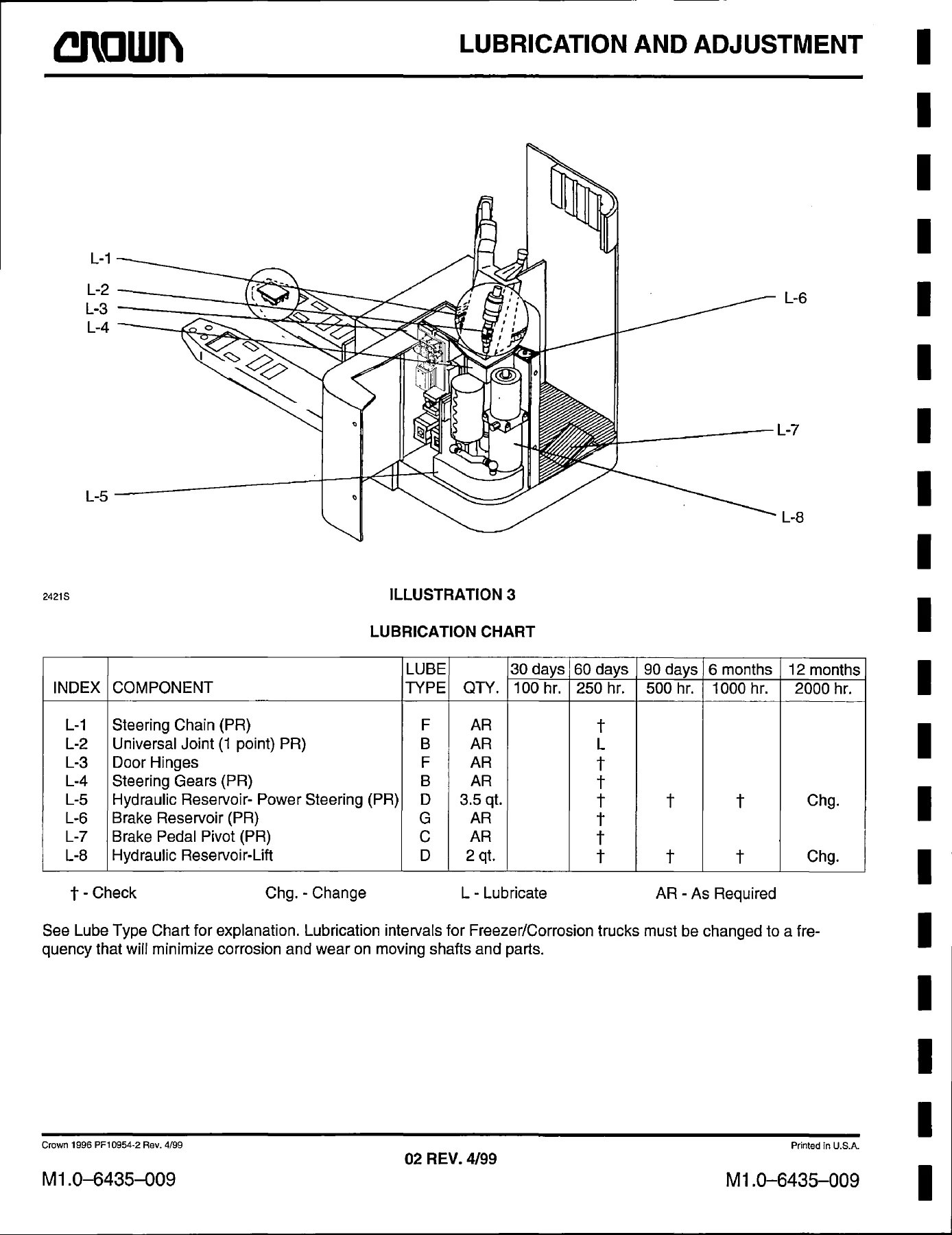
- Section M1 – Lubrication and Adjustment: Lubrication chart, inspection and adjustment chart, caster, torque values
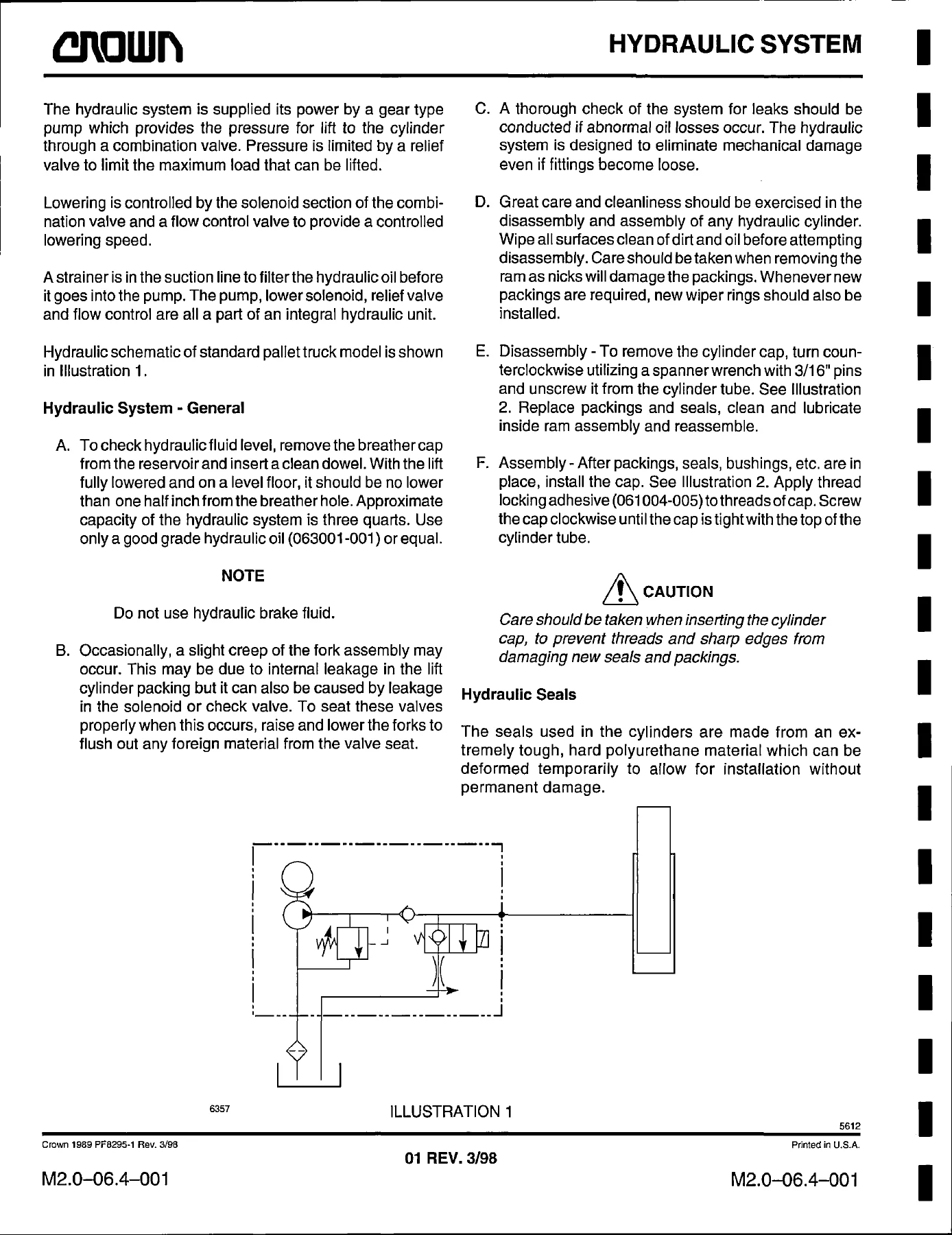
- Section M2 – Hydraulic Maintenance: General hydraulics, schematic, seals, troubleshooting chart, hydraulic schematic symbols
- Section M3 – Drive Unit Maintenance: Drive tire replacement, drive motor removal, drive unit removal, disassembly and assembly, seal replacement, thrust roller replacement, torque value chart
- Section M4 – Electrical Maintenance: Switches, gauges, electrical wiring, color codes, power cables, symbols, transistor (MOSFET) controller maintenance and operation, Sevon and Curtis transistor tune-up and troubleshooting, field weakening, anti tie down module, contactors (1A, A & B, F & R, FW), control pod switch and potentiometer adjustment, component replacement, battery, Unigage, motors, troubleshooting procedures and chart
- Section M5 – Brakes: T-handle brake adjustment and stopping distance, spring replacement, walkie-rider handle brake adjustment, stopping distance, spring replacement
- Section M7 – Fork Maintenance: 9 in. and 10 in. fork inspection, linkage adjustment
- Section M8 – Cylinder Maintenance: Lift cylinders
- Section M10 – Glossary: Component glossary cross-referencing diagrams and parts breakdowns
- Wiring Diagrams: Introduction, resistor index, transistor index, transistor and extended lift option index
- Hydraulic Schematic: Extended lift option
- Section 1 – Power Unit Parts: Power unit, caster (quick adjustment and torsion bar)
- Section 2 – Hydraulic Parts: Hydraulic system, extended lift option, pump and motor (126427, N01578), manifold (extended lift option)
- Section 3 – Drive Unit Parts: Drive unit top, drive unit bottom, motor drive, traction tire
- Section 4 – Electrical Parts: Contactor panel (resistor, Curtis, Sevcon), contactor FW, 1A, F & R, A & B, control pods for T-handle and walkie/rider handle (resistor and transistor, including freezer/corrosion versions), battery connector, console/meters, electrical/hydraulic panel for extended lift option
- Section 5 – Brake Parts: Rider brake system, walkie/rider brake system
- Section 7 – Lift Structure Parts: Entry rollers, lift linkage (single axle, tandem axle, extended lift option), battery and retainers, rollout battery, load backrest (extended lift option), fork (extended lift option), fork
- Section 8 – Cylinder Parts: Cylinder, 2nd stage cylinder (extended lift option, N01306), cylinder fork tip (extended lift option, N01346)
- Section 10 – Accessories: Skid adaptor, storage modules, labels and decals
- Section 11 – Specifications: Service specifications
Read as a whole, the Crown PC3000 Series Model 3500 Service and Parts Manual gives a technician two documents in one: a full preventative maintenance and repair guide for the PC3500 pallet truck, and a complete illustrated parts catalog. The maintenance half walks through lubrication intervals, hydraulic troubleshooting, drive unit rebuilds, brake adjustment, electrical diagnostics for both resistor and transistor control systems, and motor service. The parts half lets you look up the correct Crown part number for any assembly on the truck, using exploded views with indexed callouts that match the numbers used in the procedures. Where options exist – freezer/corrosion packages, extended lift, tandem axle, transistor vs. resistor control – the manual carries the specific diagrams and part listings for each configuration.
Model Identification and Data Number
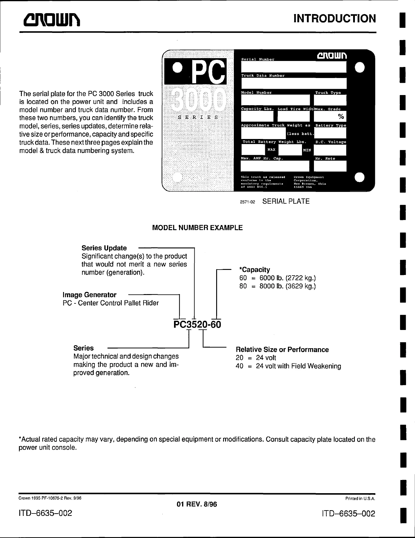
The manual opens with a serial plate example and a detailed breakdown of the Crown truck data number, showing how each block of letters and digits encodes model, capacity, fork width, fork length, battery compartment size, axle type, control type, drive tire, casters, freezer/corrosion option, travel alarm, meter options, handle type, and other features. Anyone ordering parts from the Crown PC3000 Series Model 3500 Service and Parts Manual can read their truck data plate and decode exactly which configuration they have before selecting a part number.
Specifications and Torque Data
Section M1 includes the torque value chart with Grade 5 and Grade 8 dry torque values in ft. lb., kgm, and Nm, plus specific mounting bolt torque requirements for hydraulic valves. Section M1.5 covers the quick adjustment caster with gage settings for rubber and poly drive tires, and Section M1.9 carries torque values for the tapered roller bearing, thrust bearing, and caster adjusting screw locknut. Service Specifications in Section 11 list capacity, voltage, tire sizes, lift height, travel speed, lifting and lowering speeds, brake type, motor control type, pump flow and pressure, drive unit reduction ratio, and battery ratings for the PC3520-60, PC3520-80, PC3540-60, and PC3540-80 models.
Hydraulics, Drive Unit, and Electrical Systems
The hydraulic portion of this Crown PC3000 Series 3500 Service and Parts Manual covers the gear-type lift pump, combination valve, relief valve setting, flow control, and cylinder seal installation with the U-cup installation tool procedure. The drive unit section walks through removal from the truck, upper and lower housing disassembly, pinion and gear removal, bearing and seal replacement, thrust roller service, and reassembly with torque values. The electrical section is especially deep: wiring color codes, power cable part numbers, switch-by-switch descriptions (BRES1/BRES2 battery retainer interlocks, BRS brake switch, FS/RS/AS/BS directional switches, HNS horn, HSS high speed, LMS lift limit, QPS QuickPick, RAS/LOS raise and lower, SAS safety reversing), the MOSFET transistor controller theory of operation, Sevon and Curtis transistor tune-up procedures with current limit, plugging, controlled acceleration and creep speed adjustment, and full LED fault-code troubleshooting flowcharts.
Parts Breakdowns for the Entire Truck
Every major assembly of the PC3500 has an illustrated parts breakdown: power unit frame and doors, hydraulic pump and motor assembly, lift/lower manifold, drive unit top and bottom housings, traction motor, traction tires (poly and rubber in multiple treads), contactor panels for both resistor and transistor control, control pods for T-handle and walkie/rider handle, brake system for rider and walkie/rider, lift linkage for single axle, tandem axle and extended lift option, battery retainers and rollout battery, load backrest, fork, lift cylinder, 2nd stage cylinder, fork tip cylinder, skid adaptor, and storage modules. Wiring harness numbers, connector callouts, and terminal board references are included so that the electrical diagrams and parts listings connect directly.
Who This Manual Is For
This Crown PC3000 Series Model 3500 Service and Parts Manual is aimed at the service technician, maintenance planner, or fleet owner who works on Crown PC3500 center control pallet riders. It is also useful to anyone rebuilding a used PC3520 or PC3540 truck, converting or servicing a freezer/corrosion package, adding the extended lift option, or simply keeping a printed copy of the electrical diagrams and torque values in the shop. Because the manual carries both the maintenance procedures and the parts identification in one document, it removes the need to source a separate service manual and parts catalog.
What This Manual Enables You to Do
With the Crown PC3000 Series Model 3500 Service and Parts Manual PDF on hand, a technician can perform a full PM service, adjust the caster to compensate for tire wear, rebuild a drive unit with correct bearing preload and torque, replace hydraulic cylinder seals without damaging the packing, diagnose a transistor controller fault via the LED flash codes, set the current limit and plugging distance, replace brake shoes and adjust the brake switch, inspect and adjust the fork and lift linkage, and identify the exact Crown part number for every component on the truck. Correct procedures and torque values matter on a pallet rider that carries up to 8,000 lb.; guessing at a bearing setting or brake adjustment can cost far more than the manual.
IMAGES PREVIEW
Instant PDF Delivery
The Crown PC3000 Series Model 3500 Service and Parts Manual is delivered as an instant PDF download after purchase. There is no shipping, no waiting for a physical book, and no risk of a damaged or incomplete copy. The file opens on any device – Windows PC, Mac, tablet or smartphone – and every page can be printed or zoomed for use in the workshop. Keep it on a shop tablet, print the chapters you need for the job at hand, or archive it with the rest of your Crown service literature.
Reviews
There are no reviews yet.