Description
Raymond 8300 8400 8500 8600 Pallet Truck and Tow Tractor Maintenance Manual
This is the complete Raymond maintenance manual for the Model 8300, 8400, and 8500 pallet trucks and the Model 8600 tow tractor, published as document 1106240D. It is the same service reference used to diagnose faults, remove and install components, adjust assemblies, and verify specifications across all four machines. The manual applies to serial numbers 830-09-83001, 840-09-83001, 850-09-83001, and 860-09-83001 and up. Every major system is covered: traction and travel control, lift and lower hydraulics, power-assisted and electric power steering, the brake, drive unit, battery and charging, wiring harness, and the CAN bus that links the Vehicle Manager and Traction Amplifier.
File Details
- Manual type: Maintenance Manual
- Brand: Raymond (The Raymond Corporation)
- Models covered: Model 8300, 8400, and 8500 pallet trucks; Model 8600 tow tractor
- Serial numbers: 830-09-83001, 840-09-83001, 850-09-83001, and 860-09-83001 and up
- Publication number: 1106240D
- Reissued: 27 Jan 2012
- Language: English
- File format: PDF
- Page count: 373 pages
- Electronic format: Interactive Electronic Technical Manual (IETM) with linked navigation
Chapters Covered
- Section 1 – How To Use This Manual: Manual Design, Interactive Electronic Technical Manuals, Abbreviations and Symbols, START Page
- Section 2 – Safety: Definitions, General Safety, Battery Safety, Jacking Safety (Tractor Section and Fork Section), Tie-Down for Transport, Towing, Static Safety, Welding Safety
- Section 3 – Systems Overview: Truck Model Identification, Lift Truck Specifications, Special Tools and Service Key, Operator Display and Programming, FlashWare overview and installation
- Section 4 – Scheduled Maintenance: Maintenance Guidelines, Initial 90 Day or 250 Deadman Hours (HD) Maintenance, Every 180 Days or 500 Deadman Hours, Every 360 Days or 2000 Deadman Hours, Contactor Tip Inspection, Grease Fittings (all models and trucks without composite bushings)
- Section 5 – Troubleshooting: Troubleshooting Flowcharts (TS1 START, GEN1 General, END1 End Procedure), Electrical Troubleshooting Guidelines, CAN Bus Troubleshooting, Shorts to Frame Test, Fuses, DC Electric Motors, AC Electric Motors, Hydraulic Troubleshooting Guidelines, Lift/Lower Symptom Tables, Travel (Forward/Reverse) Symptom Tables, Wiring System Symptom Tables
- Section 6 – Messages and Codes: Traction Amplifier LED Diagnostics, Traction Amplifier Flash Codes, Caution Codes (C-series), Error Codes (E-series), Power Assisted Steering Caution Codes, Electric Power Steering Caution Codes
- Section 7 – Component Procedures: Steering and Controls, Power Assisted Steering, Electric Power Steering, Control Handle Assemblies, Drive and Brake, Drive Unit, Steering Bearing, Drive Wheel, Casters (with and without springs), Brake, Electrical Components, Battery, Power Cables, Wiring Harness, AMP Water-Resistant Connectors, Traction Amplifier, Motors, Traction Motor, Lift Motor, Hydraulic Components, Hydraulic Unit, Hydraulic Reservoir, Hydraulic Pump, Hydraulic Ram, Hydraulic Cylinder Seals, Top Linkage Subassembly, Pull Rod Subassembly, Load Wheels, Pallet Entry Sliders, Pallet Entry Rollers, Fork Height Adjustment, Cold Storage Conditioning
- Section 8 – Theory of Operation: Definitions, Traction System (Vehicle Manager and Traction Amplifier), Lift/Lower System, Power Assisted Steering, Electric Power Steering, Pinout Matrix (standard, power assisted steering, electric power steering)
- Appendix: Lubrication Equivalency Chart, Thread Adhesives, Sealants, and Lubricants, Component Specific Service/Torque Chart, Torque Chart Standard (Ferrous), Torque Chart Standard (Brass), Torque Chart Metric, Torque Chart Thread-Forming Screws, Decimal Equivalent Chart, Standard/Metric Conversions
- Index and Schematics: Alphabetical index plus the schematics publication (1123028C) covering Models 8300, 8400, 8500, and 8600 with and without power steering, the options sheet, component legend, power distribution diagram, and hydraulic schematic
Read together, the manual forms a complete service loop. A technician can identify the truck and its options, find the right scheduled-maintenance interval, run a symptom or fault code through the troubleshooting tables, pull the affected component procedure with its torque values and thread-locking compound part numbers, and confirm operation against the theory-of-operation and pinout references. Maintenance intervals are broken out by operating condition – light to moderate, severe, and extreme – so the same truck can be serviced correctly for its working environment. The appendix consolidates lubrication, sealant, and torque data in one place, and the schematics publication rounds out the wiring and hydraulic side.
Diagnostics and Fault Codes
Section 5 and Section 6 are the diagnostic core. The symptom tables address no lift, slow lift, no lower, inability to pick up a load, slow lower, load drifting, no travel, slow travel, no emergency reverse, no rabbit speed, and jog speed faults, each with possible causes and the matching action. The traction amplifier LED display modes and flash codes are documented, and the caution and error codes are listed individually with the system response, the reason the code sets, the tests to run, and how to clear it. Codes C14 through C90 and E101 through E253 are covered, including the power-assisted steering set for the 8400 and the electric power steering set for the 8500 and 8600.
Component Service, Hydraulics, and Drive Unit
The component procedures section is where the manual earns its keep on a shop floor. It walks through power-assisted and electric power steering service, control handle removal and repair, drive unit removal and gear assembly with shim-pack measurement, steering bearing replacement, brake rotor replacement and gap checking, caster shimming and adjustment, battery removal with and without gates and rollers, power cable repair with the manual crimp tool, AMP water-resistant connector pin extraction and insertion, traction amplifier removal and installation, traction motor disassembly and reassembly with torque sequences, lift motor removal, hydraulic unit, reservoir, pump, ram, and cylinder seal service, top linkage and pull rod subassembly work, load wheel replacement, and fork height adjustment with the eccentric pin settings. Torque values, thread-locking compound numbers, and adjustment tolerances are given at each step.
Complete PDF Bookmark Tree
Complete Bookmarks
The complete bookmarks in the βRaymond 8300 8400 8500 8600 Pallet Truck and Tow Tractor Maintenance Manual – PDF Downloadβ are as follows:
Cover Pagep. 1
Table of Contentsp. 3
+Page Revision Recordp. 13
Document Revision Historyp. 13
+Section 1. How To Use This Manualp. 17
Manual Designp. 18
Interactive Electronic Technical Manualsp. 19
Abbreviations & Symbolsp. 20
START Pagep. 22
+Section 2. Safetyp. 25
Definitionsp. 26
General Safetyp. 27
Battery Safetyp. 30
+Jacking Safetyp. 33
Tractor Sectionp. 33
Figure 2-1. Tractor Section Jacking Pointsp. 33
Fork Sectionp. 33
+Tie-Down for Transportp. 34
Figure 2-2. Tie-Down for Transportp. 34
Towingp. 35
+Static Safetyp. 36
Figure 2-3. Anti-Static Kit (P/N 1-187-059) With Wrist Strap and Matp. 36
Welding Safetyp. 37
+Section 3. Systems Overviewp. 39
Introductionp. 40
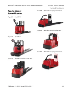
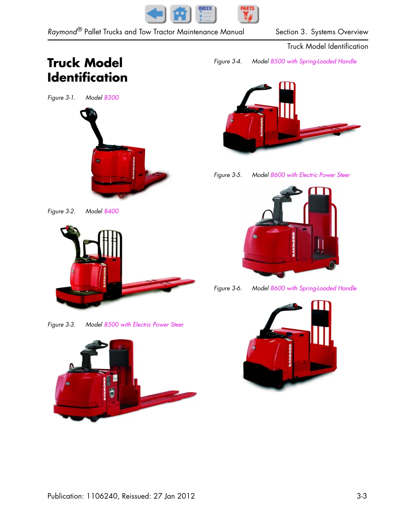
+Truck Model Identificationp. 41
Figure 3-1. Model 8300p. 41
Figure 3-2. Model 8400p. 41
Figure 3-3. Model 8500 with Electric Power Steerp. 41
Figure 3-4. Model 8500 with Spring-Loaded Handlep. 41
Figure 3-5. Model 8600 with Electric Power Steerp. 41
Figure 3-6. Model 8600 with Spring-Loaded Handlep. 41
+Lift Truck Specificationsp. 42
Figure 3-7. Lift Truck Specification Plate – Models 8300, 8400, and 8500 Pallet Trucksp. 42
Figure 3-8. Lift Truck Specification Plate – Model 8600 Tow Tractorp. 42
+Special Toolsp. 43
Service Keyp. 43
Figure 3-9. Service Keyp. 43
+Operator Display and Programmingp. 44
Figure 3-10. Operator Displayp. 44
Special Truck Modep. 44
Hour Meter (H)p. 44
+Error Codes (E)p. 44
+Changing Truck Parameters (P)p. 45
Programming Operator Parametersp. 45
Programming Service Parametersp. 47
Service Parameter Display (Keypad Only)p. 47
Setting Individual PIN-Key Codes (Keypad Only)p. 47
Display Part Numbers (Pn)p. 51
Diagnostic Test Display (D)p. 51
Service Input/Output Displaysp. 52
Figure 3-11. Service Key Connection Pointp. 52
Figure 3-12. Operator Displayp. 52
+Digital Inputs/Outputs from Traction Amplifier and VMp. 53
Traction Amplifier Inputsp. 53
Traction Amplifier Outputsp. 53
Digital Input From VM Control Sensorsp. 54
+FlashWarep. 55
Overviewp. 55
Requirementsp. 55
Installing FlashWare on PCp. 55
Connecting PC to Truckp. 55
Starting FlashWarep. 55
Figure 3-13. Truck Opening Screen with Menup. 55
Configuration and Truck Setup Optionsp. 56
+Figure 3-14. Typical Truck Setup Screenp. 56
Changing Truck Parameters:p. 56
Figure 3-15. Change Parameterp. 57
+Figure 3-16. Send Changes Buttonp. 57
Figure 3-17. Truck Setup Screen Software Buttonp. 58
+Figure 3-18. Truck Software Windowp. 59
Erase Vehicle Managerp. 59
+Figure 3-19. Erase Vehicle Manager Software Screenp. 59
Reset Defaultsp. 59
Diagnosticsp. 60
+Figure 3-20. Truck Diagnostics Screenp. 60
Error Logp. 60
RE_Read Truck Settingsp. 60
SAVE Settings to Filep. 60
SEND Changes to Truckp. 60
+Section 4. Scheduled Maintenancep. 61
Maintenance Guidelinesp. 62
Initial 90 Day/250 Deadman Hours (HD) Maintenancep. 63
Every 180 Days or 500 Deadman Hoursp. 64
Every 360 Days or 2000 Deadman Hours (HD)p. 66
Contactor Tip Inspectionp. 67
+Grease Fittings (All Models)p. 68
Figure 4-1. Caster Grease Fittingsp. 68
Figure 4-2. Load Wheel Grease Fittingsp. 68
+Grease Fittings (Trucks without Composite Bushings Only)p. 69
Figure 4-3. Upper Bell Crank Grease Fittings (Between Tractor and Fork Section)p. 69
Figure 4-4. Lower Bell Crank Grease Fittings-left side shown (Between Tractor and Fork Section)p. 69
Figure 4-5. Lower Bell Crank Grease Fittings-left side shown (Between Tractor and Fork Section)p. 69
Figure 4-6. Fork Grease Fittings (Top View)p. 69
+Section 5. Troubleshootingp. 71
How to Use This Sectionp. 72
+Troubleshooting Flowchartsp. 73
TS1: START TROUBLESHOOTINGp. 73
Figure 5-1. TS1: START TROUBLESHOOTINGp. 73
GEN1: General Troubleshootingp. 74
Figure 5-2. GEN1: General Troubleshootingp. 74
END1: End of Troubleshooting Procedurep. 75
Figure 5-3. END1: End of Troubleshooting Procedurep. 75
+Electrical Troubleshooting Guidelinesp. 76
+Troubleshooting the CAN Busp. 76
Test the Main Wire Harnessp. 77
Test the Stem Harnessp. 77
Test the Grab Railp. 77
Test the Traction Amplifier and Vehicle Managerp. 77
Shorts to Frame Testp. 78
+Fusesp. 81
Figure 5-4. Fuse Locationp. 81
Test/Inspectionp. 81
+DC Electric Motorsp. 82
DC Motor Typesp. 82
Figure 5-5. Motor Circuitsp. 82
Inspectionp. 82
Servicep. 82
Open Circuit Motor Testp. 84
Grounded Motor Testp. 85
Short-Circuited Armaturep. 85
Short-Circuited Windingp. 85
+AC Electric Motorsp. 86
AC Motor Typep. 86
Figure 5-6. AC Traction Motor circuit – Phase Ap. 86
Figure 5-7. AC Traction Motor circuit – Phase Bp. 86
Open Windingp. 86
Shorted Windingp. 86
Hydraulic Troubleshooting Guidelinesp. 87
+Symptom Tables: Lift/Lower Systemp. 88
No Lift, Lift Motor Does Not Run, Travel is OK (From control handle or grab rail switch)p. 88
No Lift or Slow Lift, Lift Motor Does Runp. 89
No Lower, Lift and Travel OKp. 89
Unable to Pick Up a Loadp. 90
Slow Lowerp. 90
Load Drifting/Settlingp. 90
+Symptom Tables: Travel (Forward/Reverse) Systemp. 91
No Travel, Lift/Lower OK. Main Contactor Does Not Close. TA Amber LED is Flashing Once Every 2 Secondsp. 91
No Travel, No Lift/Lower. TA Flash Code 3,1. Operator Display May Indicate Error Code E106p. 91
No Travel, No Lift/Lower. TA Flash Code 1,3. Operator Display Indicates Error Code E202p. 92
No Travel, No Lift/Lower. TA Flash Code 1,2. Operator Display Indicates Error Code E201p. 92
No Travel, Main Contactor Does Not Close. TA Flash Code 3,9. Operator Display Indicates Error Code E107p. 92
No Travel or Slow Travel. Main Contactor Does Close. TA Flash Code 2,1. Operator Display Indicates Error Code Cold (C43)p. 93
Slow Travel, Lift/Lower OK. No Fault Codesp. 93
No Emergency Reverse, Travel/Lift/Lower OK. No TA Flash Codesp. 93
No Rabbit Speed, Travel/Lift/Lower OK. No Fault Codesp. 93
No Truck Functions Active. TA Flash Code 1,8, (Excessive Battery Voltage). Operator Display May Indicate E222p. 94
No Truck Functions Active. TA Flash Code 1,7, (Low Battery Voltage). Operator Display May Indicate E221p. 94
No Travel or Slow Travel. TA Flash Code 2,2, (Thermal Cutback) Heatsink Temperature Exceeded 185Β°F (85Β°C). Operator Display May Indicate Hot2 (C45)p. 94
No Travel. Static Return to OFF (SRO) Fault. Display may indicate βSroβ and Error and Parameter Control Indicators Blinkingp. 95
No Travel. High Pedal Disable Fault. Display may indicate βHPdβ and Error and Parameter Control Indicators Blinkingp. 95
Truck Does Not Accelerate Correctlyp. 95
Jog Speed Does Not Activate and Handle Does Not Stay in Coast Position. Lift and Travel OK. (Model 8400 with Coast PRO β’)p. 96
Jog Speed Does Not Activate. Lift and Travel OK. (Center Rider Models Only with Fixed-Position Handle)p. 96
Jog Speed Does Not Function, Handle Does Stay in Coast Position. Lift and Travel OK (Model 8400 with Coast PRO β’)p. 96
Symptom Tables: Wiring Systemp. 97
+Section 6. Messages and Codesp. 99
List of Messages and Codesp. 100
+Traction Amplifier LED Diagnosticsp. 103
Figure 6-1. Traction Amplifier Status Indicator LEDp. 103
Traction Amplifier Flash Codesp. 104
+Caution and Error Codesp. 106
Figure 6-2. Operator Displayp. 106
+Caution Codesp. 107
Code βGATEβp. 107
Code βSLOβp. 107
Code βSroβ (C14)p. 107
Code C15p. 108
Code C19p. 108
Code HPd (C20)p. 108
Code C21p. 109
Code C22p. 109
Code C24p. 109
Code C25p. 110
Code C26p. 110
Code C27p. 110
Code C30p. 111
Code C31p. 111
Code C32p. 111
Code C33p. 112
Code C34p. 112
Code C35p. 112
Code Lo (C41)p. 113
Code Hi (C42)p. 113
Code Hot1 (C44)p. 114
Code Hot2 (C45)p. 114
Code C46 (iWarehouse Only)p. 114
Code C47 (iWarehouse Only)p. 115
Code C50p. 115
Code C51p. 115
Code C52p. 116
Code C57p. 116
Code C60p. 116
Code C61p. 117
Code C62p. 117
Code C63p. 117
Code C64p. 118
Code C65p. 118
Code C66p. 118
Code C67p. 119
Code C68p. 119
Code C70p. 119
Code C71p. 120
Code C72p. 120
+Error Codesp. 121
Code E101p. 121
Code E106p. 121
Code E107p. 122
Code E108p. 122
Code E140p. 123
Code E141p. 123
Code E150p. 123
Code E157p. 124
Code E159p. 124
Code E160p. 124
Code E201p. 125
Code E202p. 125
Code E203p. 126
Code E220p. 126
Code E221p. 127
Code E222p. 127
Code E223p. 128
Code E224p. 128
Code E225p. 128
Code E228p. 129
Code E230p. 129
Code E232p. 129
Code E233p. 130
Code E235p. 130
Code E252p. 130
Code E253p. 131
+Power Assisted Steering Caution Codesp. 132
Code C36p. 132
Code C74p. 132
Code C75p. 132
Code C76p. 133
Code C77p. 133
Code C78p. 133
Code C79p. 134
Code C80p. 134
Code C81p. 134
Code C82p. 135
Code C83p. 135
Code C84p. 135
Code C85p. 136
Code C86p. 136
Code C90p. 136
+Electric Power Steering Caution Codesp. 137
Code C36p. 137
Code C74p. 137
Code C75p. 138
Code C76p. 138
Code C77p. 138
Code C78p. 139
Code C79p. 139
Code C80p. 140
Code C81p. 140
Code C82p. 141
Code C83p. 141
Code C84p. 142
Code C85p. 142
Code C86p. 143
Code C87p. 143
Code C88p. 143
Code C89p. 144
Code C90p. 144
+Section 7. Component Proceduresp. 145
List of Component Procedures by Truck Systemp. 146
+Component Locator Photosp. 149
Figure 7-1. Inside Tractor, Rear Viewp. 149
Figure 7-2. Inside Tractor, Right Sidep. 150
Figure 7-3. Inside Tractor, Left Sidep. 151
Figure 7-4. Model 8400 (Long-John Forks Shown)p. 152
Figure 7-5. Model 8400 Control Handlep. 153
+Steering and Controlsp. 155
+Power Assisted Steeringp. 156
Replacing the Pinion Gearp. 156
Figure 7-6. Pinion Gear Replacementp. 156
Figure 7-7. Mounting Bolt Detailp. 156
Replacing the Power Steer Unitp. 157
Figure 7-8. Power Steer Unit Replacementp. 157
Removing the Power Steering Sensor Cardp. 158
Figure 7-9. Power Steer Sensor Card Removal/Installationp. 158
Figure 7-10. Lower Cover Removalp. 159
Installing the Power Steering Sensor Cardp. 159
Figure 7-11.p. 159
+Learn Steerp. 160
Learning Steer with FlashWarep. 160
Learning Steer with a Service Keyp. 160
+Checking the Steer Positionp. 160
Steer Position Check – Method 1p. 160
Steer Position Check – Method 2p. 160
Replacing the Handle Centering Bumpersp. 161
Figure 7-12. Lower Cover Removalp. 161
Figure 7-13. Bumper Removalp. 161
Replacing the Handle Pivot Mechanismp. 162
Figure 7-14. Lower Cover Removalp. 162
Figure 7-15. Upper Cover Removalp. 162
Figure 7-16. Pivot Mechanism Replacementp. 163
Figure 7-17. Pivot Shaft Bearingsp. 164
+Electric Power Steeringp. 166
+Electric Power Steer Handle and Post Assemblyp. 166
Removing Handle and Postp. 166
+Figure 7-18. Post Assembly Mounting Screwsp. 166
Installing Handle and Postp. 166
+Handle Height Adjustmentp. 167
Standard Handle Height Adjustmentp. 167
+Figure 7-19. Height Adjustment – Standard Handlep. 167
Premium Handle Height Adjustmentp. 167
Figure 7-20. Height Adjustment – Premium Handlep. 167
Control Head – Standard Handlep. 168
+Figure 7-21. Control Head/Arm and Post Disassemblyp. 168
Standard Control Head Installationp. 168
Control Head – Premium Handlep. 169
+Figure 7-22. Control Head Mounting Screwsp. 169
Premium Control Head Installationp. 169
Offset (Home) Sensor Proximity Switch (SW23)p. 171
Offset Sensor Replacementp. 171
Figure 7-23. Offset Sensor Plate Mounting Screwsp. 171
Figure 7-24. Setting Sensor Gapp. 171
+Gas Springsp. 172
Post Gas Spring Replacementp. 172
Figure 7-25. Post Gas Spring Replacementp. 172
Control Handle – Model 8300p. 173
Figure 7-26. Model 8300 Control Head Assembly – Exploded Viewp. 173
Control Handle Disassemblyp. 174
Changing Horn Button/Switchp. 174
Figure 7-27. Horn Button Removalp. 174
Changing Lift/Lower Buttonp. 175
Figure 7-28. Lift/Lower Button Removalp. 175
Changing Push Buttonp. 175
Figure 7-29. Push Button Removalp. 175
+Spring-Loaded Handle Designp. 176
Spring-Loaded Handle Removalp. 176
Figure 7-30. Control Handle Base Cover Removalp. 176
Figure 7-31. Control Handle Wire Harnessp. 176
Figure 7-32. Remove Jam Nut at Coast Linkp. 176
Figure 7-33. Return Spring Rod Removalp. 177
Spring-Loaded Handle Installationp. 177
Return Spring Adjustment, Spring-Loaded Handlep. 177
Figure 7-34. Return Spring Adjustmentp. 177
+Fixed-Position Handle Design – Models 8500 and 8600p. 179
Fixed-Position Handle Removalp. 179
Fixed-Position Handle Installationp. 179
+Control Handle Assembliesp. 180
Figure 7-35. Control Handle and Head Assembly – Model 8400 (Spring-Loaded Handle)p. 180
Figure 7-36. Control Handle with Hand Brake – Model 8500 and 8600 (Fixed Handle)p. 181
Figure 7-37. Control Handle with Deadman Brake – Model 8500 and 8600 (Spring-Loaded Handle)p. 182
Figure 7-38. Control Head Assembly (Models 8400, 8500, and 8600) – Exploded Viewp. 183
Control Head Removalp. 184
Changing Horn Button/Switchp. 184
Figure 7-39. Horn Button Removalp. 185
Changing Lift/Lower Switch Activatorp. 185
Figure 7-40. Lift/Lower Button Removalp. 185
Changing the Push Buttonp. 185
Figure 7-41. Push Button Removalp. 185
Figure 7-42. Handle with Jog Optionp. 186
Changing the Jog Switchp. 186
Changing the Jog Button Control and Springp. 186
+Drive and Brakep. 187
+Drive Unitp. 188
Removing the Drive Unitp. 188
Figure 7-43. Drive Unit Fill Plugp. 188
Figure 7-44. Drive Unit Drain Plugp. 188
Figure 7-45. Drive Unit Mounting (Traction Motor Removed)p. 188
+Steering Bearingp. 189
Removing the Steering Bearingp. 189
Figure 7-46. Drive Unit (Shown installed in Tractor Frame)p. 189
Figure 7-47. Drive Unit Bottom Viewp. 189
Figure 7-48. Drive Unit, Steering Bearing Removedp. 189
Installing the Steering Bearingp. 189
Figure 7-49. Main Case Cover, Six Hole-Type, Installedp. 190
Figure 7-50. Gear Housing and Coverp. 190
Assembling the Gearp. 190
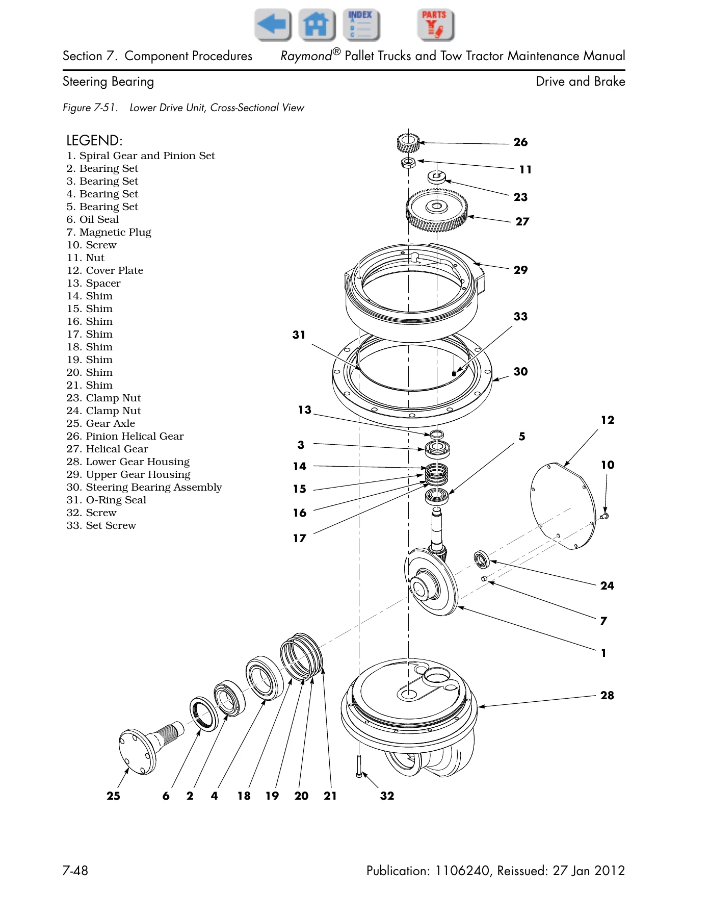
Figure 7-51. Lower Drive Unit, Cross-Sectional Viewp. 192
Checking the Gearsp. 193
Adjusting Tooth Pattern of Drive Unitp. 193
Figure 7-52. Drive Unit Gear Tooth Patternp. 193
Installing the Drive Unitp. 194
Figure 7-53. Drive Unit Gauge and Shimming Locationsp. 194
Figure 7-54. Drive Unit Mounting Screw Torque Sequencep. 195
Figure 7-55. Drive Unit Drain Plugp. 195
Drive Housing Lubricationp. 195
+Drive Wheelp. 196
Removing the Drive Wheelp. 196
Figure 7-56. Drive Wheel and Tirep. 196
Cushion Tire Replacementp. 196
Figure 7-57. Cushion Tire Replacementp. 196
+Caster Adjustmentp. 198
Figure 7-58. Drive Tire on Platep. 198
+Casters (without Springs)p. 199
Caster Removalp. 199
Figure 7-59. Removing Caster Wheel Assemblyp. 199
Wheel Replacementp. 199
Figure 7-60. Caster Assembly, Disassembledp. 199
Caster Assemblyp. 199
Figure 7-61. Caster Assembly, Assembledp. 200
Caster Installationp. 200
+Figure 7-62. Securing Caster To Tractorp. 200
Adjustable Caster Adjustmentp. 200
Figure 7-63. Adjustable Caster Adjustmentp. 200
+Casters (Spring-Loaded)p. 201
Spring-Loaded Caster Removalp. 201
Figure 7-64. Removing Spring-Loaded Casterp. 201
Wheel Replacementp. 201
Figure 7-65. Removing Tension Pinp. 201
Figure 7-66. Removing Axle Shaftp. 201
Figure 7-67. Removed Wheel and Shimsp. 201
Caster Disassemblyp. 202
Figure 7-68. Compressing Caster Springsp. 202
Figure 7-69. Relieving Pivot Tensionp. 202
Figure 7-70. Removing Pivot Pin Retainer Screwp. 202
Figure 7-71. Removing Pivot Pinp. 202
Figure 7-72. Separated Casterp. 202
Caster Assemblyp. 203
Figure 7-73. Removing Bolts from Springsp. 203
Wheel Installationp. 203
Figure 7-74. Installing New Wheelp. 203
Figure 7-75. Installing Axle Shaftp. 203
Figure 7-76. Installing Tension Pinp. 203
Spring-Loaded Caster Installationp. 204
Figure 7-77. Caster, Shims and Mounting Boltsp. 204
Figure 7-78. Securing Caster To Tractorp. 204
+Brakep. 205
Spring-Loaded Handlep. 205
Figure 7-79. Brake Release Bolt Storage Locationp. 205
Brake Removal, Spring-Loaded Handlep. 205
Figure 7-80. Brake Release Bolts, Installedp. 205
Figure 7-81. Brake Release Bolts, Installedp. 205
Brake Installation, Spring-Loaded Handlep. 205
Checking the Gapp. 206
Figure 7-82. Measuring Brake Gapp. 206
Replacing the Rotorp. 206
+Electrical Componentsp. 207
+Batteryp. 208
+With Battery Gates and Rollers (Optional)p. 208
Battery Removalp. 208
Battery Installationp. 208
+Battery Gates (Optional)p. 208
Battery Gate Inspectionp. 208
+Battery Rollers (Optional)p. 208
Battery Roller Inspectionp. 208
Battery Roller Replacementp. 208
+Without Battery Gates and Rollersp. 208
Battery Removalp. 208
Battery Installationp. 208
Battery Exterior Cleaningp. 209
Figure 7-83. Battery Filler Plugs and Vent Holesp. 209
Testing, Charging, and Maintenancep. 209
Maintenance-Free Batteriesp. 210
Battery Storagep. 210
+Power Cablesp. 211
Power Cable Repairp. 211
Figure 7-84. Short Barrel Terminalp. 211
Figure 7-85. Long Barrel Terminalsp. 212
+Wiring Harnessp. 213
Wiring Harness Terminologyp. 213
Inspecting a Wiring Harnessp. 213
Repairing a Wiring Harnessp. 213
Wiring Harness Soldering Proceduresp. 214
+AMP Water-Resistant Connectorsp. 215
Figure 7-86. AMP Water-Resistant Connectorp. 215
AMP Connector Pin Extractionp. 215
Figure 7-87. AMP Pin Extractionp. 215
Figure 7-88. Removing Wirep. 216
AMP Connector Pin Insertionp. 216
Figure 7-89. Wire Sealp. 216
Figure 7-90. Wire Insertionp. 216
AMP Connector Sealsp. 216
Figure 7-91. Sealing Plugp. 216
Figure 7-92. Interface Sealp. 217
Figure 7-93. Latching AMP Connectorp. 217
+AMP Harness/Traction Amplifier Connectorp. 218
AMP Harness Connector Componentsp. 218
Figure 7-94. JPT1 Connector Componentsp. 218
AMP Harness Connector Disassembly (Contact Removal)p. 218
Figure 7-95. AMP Connector (JT1 or JL1)p. 218
AMP Harness Connector Contact Insertionp. 218
AMP Harness Connector Assemblyp. 219
Figure 7-96. Contact Insertionp. 219
Figure 7-97. Wedge Lock Latchesp. 220
Figure 7-98. Wedge Lock Flush With Housingp. 220
Testing AMP Harness Connectorsp. 220
+Brake Potentiometer (VR1)p. 221
Removing VR1p. 221
Figure 7-99. Pot Cover Screw Locationsp. 221
Figure 7-100. Brake Control Assembly – Exploded Viewp. 221
Installing VR1p. 221
+Lift-Limit Switch (SW8)p. 222
Figure 7-101. Lift-Limit Switchp. 222
Adjusting the Limit Switchp. 222
+Grab Rail Switches – Model 8400p. 223
Removing Grab Rail Switchesp. 223
Figure 7-102. Grab Rail Switch Removal, Left Sidep. 223
Figure 7-103. Grab Rail Switch Removal, Right Sidep. 223
Installing Grab Rail Switchesp. 223
+Load Backrest Switches – Model 8500 Optionp. 224
Removing Load Backrest Switchesp. 224
Figure 7-104. Load Backrest Switches, Detail Viewp. 224
Figure 7-105. Load Backrest Switches, Cover Plate Openp. 224
Installing Load Backrest Switchesp. 224
+Hydraulic Solenoidsp. 225
Figure 7-106. Hydraulic Solenoids (typical unit)p. 225
+Coast PRO β’ Solenoid – Model 8400 Optionp. 226
Removing the CoastPro Solenoidp. 226
Figure 7-107. Coast PRO Solenoid Locationp. 226
Figure 7-108. Socket Head Cap Screwsp. 226
Figure 7-109. Removed Solenoid Mechanismp. 226
Installing the CoastPro Solenoidp. 227
Figure 7-110. Install Ball Bearingsp. 227
+Coast Solenoid Switch/Springp. 227
Removing Coast Solenoid Switchp. 227
Installing Coast Solenoid Switch/Springp. 227
+Coast PRO Canisterp. 227
Removing the CoastPro Canisterp. 227
Installing the CoastPro Canisterp. 227
+Figure 7-111. Canister Spacingp. 227
Repairing the CoastPro Canisterp. 228
Figure 7-112. Special Compression Toolp. 228
Figure 7-113. Cylinder Secured In Hydraulic Pressp. 228
Figure 7-114. Removing Snap Ringp. 228
Figure 7-115. Coast PRO Canister Componentsp. 228
Figure 7-116. Assembling Coast PRO Canisterp. 229
+Traction Amplifierp. 230
Figure 7-117. Traction Amplifier Locationp. 230
Removing the Traction Amplifierp. 230
Figure 7-118. Removing the Traction Amplifierp. 230
Installing the Traction Amplifierp. 230
Programming the Traction Amplifierp. 231
+Motors, Generalp. 232
Terminal Nutsp. 232
Figure 7-119. Traction Motor Terminal Connectionsp. 232
Figure 7-120. Lift and Auxiliary Motor Terminal Nutsp. 232
+Traction Motorp. 233
Removing the Traction Motorp. 233
Figure 7-121. Control Handle Base Cover Removalp. 233
Figure 7-122. Control Handle Base Cover Removalp. 234
Figure 7-123. Traction Motor Power Cablesp. 234
Figure 7-124. Traction Motor Removalp. 235
+Figure 7-125. Drive Unit Pinion Gearp. 235
Installing the Traction Motorp. 235
+Figure 7-126. Main Case Locationp. 235
Installing Temperature Sensorp. 236
Figure 7-127.p. 236
+Figure 7-128.p. 236
Terminal Board Removal and Replacementp. 236
+Figure 7-129.p. 237
+Figure 7-130.p. 237
Figure 7-131. Bolt Tightening Sequencep. 239
+Lift Motorp. 240
General Datap. 240
Removing the Lift Motorp. 240
Figure 7-132. Bolts Securing Motor To Adapterp. 240
Figure 7-133. Separated Reservoir and Motor (typical)p. 240
Installing the Lift Motorp. 240
Figure 7-134. Coupling Cavityp. 241
Figure 7-135. Indexing Pinp. 241
+Hydraulic Componentsp. 243
+Hydraulic Componentsp. 244
General Guidelinesp. 244
Figure 7-136. Hydraulic Unit (typical shown)p. 244
+Hydraulic Fluidp. 245
Checking Hydraulic Fluid Levelp. 245
+Hydraulic Unitp. 246
Removing the Hydraulic Unitp. 246
Figure 7-137. Hydraulic Unit (typical shown)p. 246
Installing the Hydraulic Unitp. 246
+Hydraulic Reservoirp. 247
Removing the Hydraulic Reservoirp. 247
Figure 7-138. Adapter Cap Screwsp. 247
Figure 7-139. Removed Reservoirp. 247
Installing the Hydraulic Reservoirp. 247
+Filter Screen and Suction Tubep. 248
Removing Filter Screen and Suction Tubep. 248
Figure 7-140. Pump Housing Componentsp. 248
Figure 7-141. Cleaning Filter Screenp. 248
Installing Filter Screen and Suction Tubep. 248
+Hydraulic Pumpp. 249
Removing the Pumpp. 249
Figure 7-142. Pump and Adapter Bodyp. 249
Installing the Pumpp. 249
Figure 7-143. Pump Drive Couplingp. 249
Figure 7-144. Installing Pump In Adapterp. 249
+Adjusting Hydraulic Pump Relief Valve Pressurep. 250
Figure 7-145. Checking Relief Valve Pressurep. 250
Checking Relief Valve Settingp. 250
Alternate Method Using Rated Load on Palletsp. 250
+Hydraulic Ramp. 252
Inspecting Hydraulic Ramp. 252
Removing Hydraulic Ramp. 252
Figure 7-146. Removing Lower Bell Crank Pinsp. 252
Figure 7-147. Disconnecting Upper Clevis Bracketsp. 253
Figure 7-148. Hydraulic Ram Area, Forks Removedp. 253
Figure 7-149. Hydraulic Line Connectionp. 253
Figure 7-150. Vent Hose Connectionsp. 253
Installing Hydraulic Ramp. 254
Figure 7-151. Hydraulic Ram Removal/Installationp. 254
Figure 7-152. Hydraulic Line Connection (installed)p. 254
+Hydraulic Cylinder Sealsp. 255
Disassembling the Cylinderp. 255
Figure 7-153. Remove Outer Spiral Lock Ringp. 255
Figure 7-154. Remove the Spacerp. 255
Figure 7-155. Remove Head Lock Ring From Cylinderp. 255
Figure 7-156. Rod and Head Assembly Out of Cylinderp. 255
Figure 7-157. Remove the Piston Jam Nutp. 256
Figure 7-158. Piston Rod Componentsp. 256
Assembling the Cylinderp. 256
Figure 7-159. Correct Piston Seal Orientationp. 256
Figure 7-160. Securing Piston Jam Nutp. 256
Figure 7-161. Installing the Head Lock Ringp. 257
Figure 7-162. Installing the Outer Lock Ringp. 257
+Mastp. 259
+Top Linkage Subassemblyp. 260
Removing the Top Linkage Subassemblyp. 260
Figure 7-163. Blocking Fork Sectionp. 260
Figure 7-164. Removing Lower Bell Crank Pinsp. 260
Figure 7-165. Disconnecting Upper Clevis Bracketsp. 261
Figure 7-166. Hydraulic Ram Area, Forks Removedp. 261
Installing the Top Linkage Subassemblyp. 261
Figure 7-167. Hydraulic Ram Area, Installationp. 261
+Pull Rod Subassemblyp. 263
Removing the Pull Rod Subassemblyp. 263
Figure 7-168. Blocking Fork Sectionp. 263
Figure 7-169. Removing Lower Bell Crank Pinsp. 263
Figure 7-170. Eccentric Pin and Retaining Screwp. 263
Figure 7-171. Machined Trail Fork Subassembly Removalp. 264
Figure 7-172. Machined Trail Fork Assemblyp. 264
Installing the Pull Rod Subassemblyp. 264
Figure 7-173. Pivot Shaft Installationp. 264
+Load Wheelsp. 266
Single Load Wheels β Models 8300, 8400, and 8500p. 266
Figure 7-174. Removing Tension Pinp. 266
Figure 7-175. Removing Axle From Load Arm Castingp. 266
Figure 7-176. Removed Load Wheel and Componentsp. 266
Tandem Load Wheels β Models 8400 and 8500p. 266
+Figure 7-177. Tandem Load Wheelsp. 267
Tandem Wheel Replacementp. 267
Load Wheel Installation, Tandemp. 267
Suspension Wheel β Model 8600p. 267
+Figure 7-178. Model 8600 Load Wheel Suspension-Exploded Viewp. 268
Suspension Wheel Installationp. 268
+Pallet Entry Slidersp. 269
Slider Replacementp. 269
6000 lb. Models (Single Pallet)p. 269
+Figure 7-179. Replacing Pallet Entry Slider (6000 lb. Standard Model Shown)p. 269
Long-John Models (Multiple Pallet)p. 269
+Pallet Entry Rollersp. 270
Roller Replacementp. 270
Figure 7-180. Replacing Pallet Entry Rollerp. 270
Figure 7-181. Replacing Pallet Entry Rollerp. 270
+Fork Height Adjustmentp. 271
+Figure 7-182. Fork Height Adjustment at Lower Bell Crankp. 271
Setting Fork Timingp. 271
Measurementp. 271
Figure 7-183. Measure Fork Height at Load Wheelp. 271
Figure 7-184. Measure Fork Height at Battery Compartmentp. 271
Downstop Installationp. 272
+Figure 7-185. Downstop Installationp. 272
Downstop Adjustmentp. 272
Figure 7-186. Eccentric Pin Adjustmentp. 272
Figure 7-187. Eccentric Pin Height Referencep. 272
Figure 7-188. Downstop Adjustmentp. 273
Pallet Entry/Exit Enhancementsp. 273
Figure 7-189. Fork Wear Patterns Before Grinding and Polishingp. 273
Figure 7-190. Fork Wear Patterns After Grinding and Polishingp. 273
Figure 7-191. Check Pull Rod Wearp. 274
+Optionsp. 275
Cold Storage Conditioningp. 276
+Section 8. Theory of Operationp. 277
+Definitionsp. 278
Acceleration Ratep. 278
Brake Lever Potentiometer (VR1) (Models with Fixed Position Handle)p. 278
Brake (Deadman) Switch (Models with Spring-Loaded Handle)p. 278
Figure 8-1. Brake (Deadman) Switch and Brake Actuationp. 278
Continuityp. 278
Controller Area Network (CAN)p. 278
Current Limitingp. 278
Emergency Reverse (Models 8300 and 8400)p. 278
Fault Codesp. 279
High Pedal Disable (HPD)p. 279
Neutral Plugging Rate (Deceleration)p. 279
Open Circuitp. 279
Overvoltage Cutoffp. 279
PIN-Key Codep. 279
Pulse Width Modulationp. 279
Ramp Shapep. 279
Regenerative Brakingp. 279
Sequencing Delayp. 280
Short Circuit or βShortβp. 280
Speed Limitingp. 280
Static Return To Off (SRO)p. 280
Thermal Cutback (Traction Amplifier)p. 280
Throttle Mapp. 281
Truck Off Delay (Keypad only)p. 281
Undervoltage Cutoffp. 281
VM (Vehicle Manager)p. 281
Walking Speedp. 281
+Traction Systemp. 282
Vehicle Manager (VM)p. 282
Traction Amplifier (TA)p. 282
Battery Plugged Inp. 282
Key Switch ON and M1 Energizedp. 282
Travel Request, Tractor-Firstp. 283
Travel Request, Forks-Firstp. 283
Strip Curtain Bypass (Model 8400 only)p. 283
Emergency Reverse (Model 8300 and 8400)p. 284
Jog Button Controls Mode (Model 8500 only)p. 284
+Coast Modep. 285
+Lift/Lower Systemp. 286
+Theory of Operation β Power Assisted Steeringp. 287
Power Steering Sensor Cardp. 287
PSU: Power Steering Unitp. 287
Steeringp. 287
+Theory of Operation – Electric Power Steeringp. 288
Power Steering Potentiometersp. 288
Floor Mat Switch (SW25) – Model 8500 onlyp. 288
Premium Control Handle – Model 8500 onlyp. 288
Travel Speed Reductionp. 288
PSU: Power Steering Unitp. 288
Steeringp. 289
Pinout Matrixp. 290
Pinout Matrix β Power Assisted Steeringp. 295
Pinout Matrix β Electric Power Steeringp. 297
+Section A. Appendixp. 299
Lubrication Equivalency Chartp. 300
Thread Adhesives, Sealants, and Lubricantsp. 301
Component Specific Service/Torque Chartp. 302
Torque Chart – Standard (Ferrous)p. 305
Torque Chart – Standard (Brass)p. 306
Torque Chart – Metricp. 307
Torque Chart – Thread-Forming Screwsp. 308
Decimal Equivalent Chartp. 309
Standard/Metric Conversionsp. 311
Section I. Indexp. 313
+Schematicsp. 318
Figure 1. Model 8300 Standardp. 319
Figure 2. Model 8400 Standardp. 320
Figure 3. Model 8500 without Power Steer (Standard Handle)p. 321
Figure 4. Model 8600 without Power Steer (Standard Handle)p. 322
Figure 5. Model 8500 with Power Steerp. 323
Figure 6. Model 8600 with Power Steerp. 324
Figure 7. Optionsp. 325
Figure 8. Component Legendp. 326
Figure 9. Power Distribution Diagramp. 327
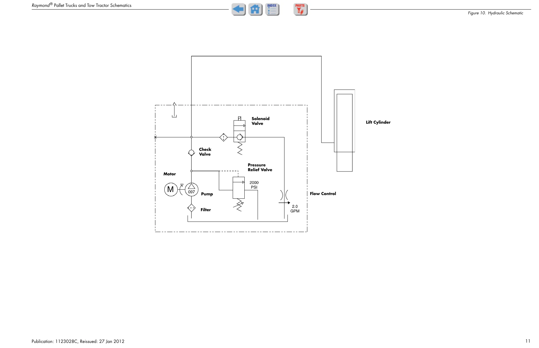
Figure 10. Hydraulic Schematicp. 328
+RSIsp. 329
RSI PLT-13-010p. 329
RSI PLT-13-009p. 330
RSI PLT-13-008p. 333
RSI PLT-13-007p. 335
RSI PLT-13-006p. 339
RSI PLT-13-003p. 341
RSI PLT-12-010Cp. 342
RSI PLT-12-010Bp. 355
RSI PLT-12-007p. 368
RSI PLT-12-004p. 369
RSI PLT-12-003Ap. 371
Put This Raymond Maintenance Manual to Work
This Raymond 8300 8400 8500 8600 Pallet Truck and Tow Tractor Maintenance Manual gives you the procedures to keep these machines running: diagnose a no-travel or no-lift complaint against the symptom tables, read and clear the C-series caution codes and E-series error codes, service the drive unit and hydraulic ram, adjust fork height and caster shims to the printed tolerances, and torque every fastener to the value the manual specifies. Correct procedures and the right specifications are what keep a pallet truck off the disabled list and away from a repair bill built on guesswork. The manual arrives as an instant PDF download – no shipping and no waiting – and opens on any device so you can print the pages you need for the job or keep it on a laptop in the shop.
Reviews
There are no reviews yet.