
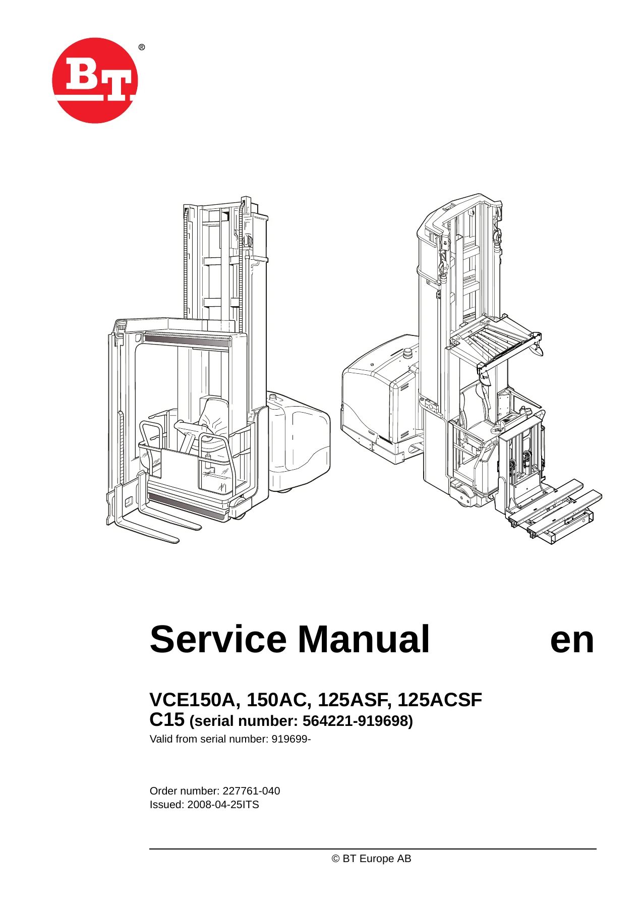
BT VCE150A VCE150AC VCE125ASF VCE125ACSF Service Manual 2008 – T Code 712 713 Workshop Repair PDF
Original price was: $61.95.$39.95Current price is: $39.95.
Complete 2008 BT service manual for VCE150A, VCE150AC, VCE125ASF and VCE125ACSF narrow-aisle trucks (T code 712 and 713). Covers preventive maintenance, chassis, drive unit, brakes, electrical system, hydraulics, masts, turret head and shuttle fork. 262-page PDF, order 227761-040.
Description
BT VCE150A, VCE150AC, VCE125ASF, VCE125ACSF Service Manual – T Code 712 & 713
This is the complete service manual for the BT VCE150A, BT VCE150AC, BT VCE125ASF and BT VCE125ACSF narrow-aisle trucks (T code 712 and T code 713), order number 227761-040, issued 2008-04-25 and valid from serial number 919699 onwards. Written in English, it is the same workshop document used for scheduled preventive maintenance, mechanical repair, hydraulic fault-finding, electrical diagnostics and component overhaul on these machines. Whether you are servicing a VCE150A turret head truck or a VCE125ASF shuttle fork machine, this manual gives you the procedures, torque figures, oil specifications and diagnostic codes you need in one place.
File Details
- Manual type: Service / Workshop Manual
- Brand: BT (BT Europe AB)
- Models covered: VCE150A, VCE150AC, VCE125ASF, VCE125ACSF
- T codes: 712, 713
- Serial number range: valid from 919699- (earlier range 564221-919698)
- Order number: 227761-040
- Issued: 2008-04-25
- Language: English
- Page count: 262
- File format: PDF
Chapters Covered
- Preventive maintenance – P2 (T code 712)
- Preventive maintenance – P2 (T code 713)
- Oil and grease specifications – P3 (T code 712)
- Oil and grease specification – P3 (T code 713)
- Tools – P4
- Chassis – 0000
- Frame pivot – 0320
- General tightening torque – 0400
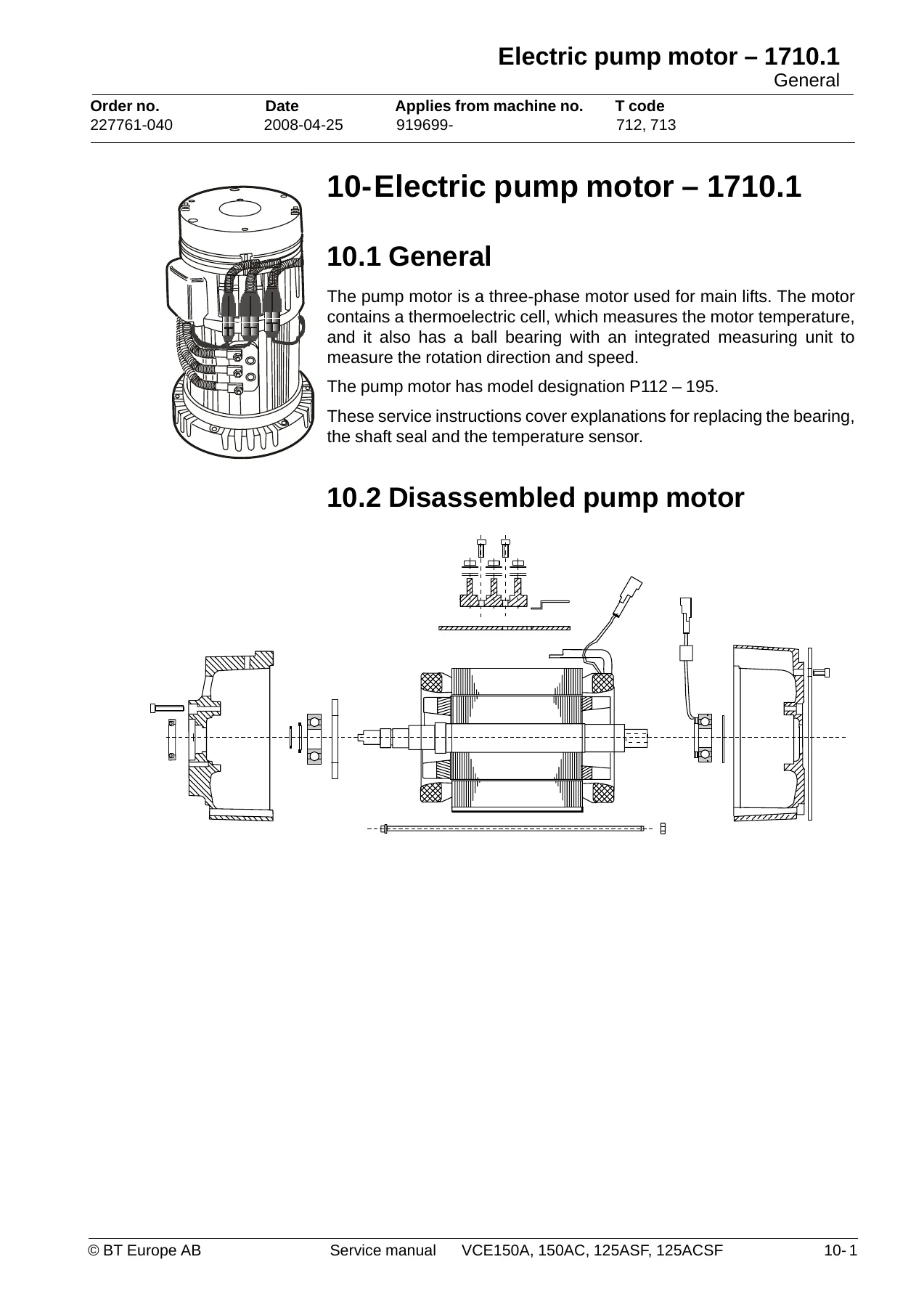
- Electric pump motor – 1710.1
- Electric pump motor – 1710.2
- Electric drive motor – 1760
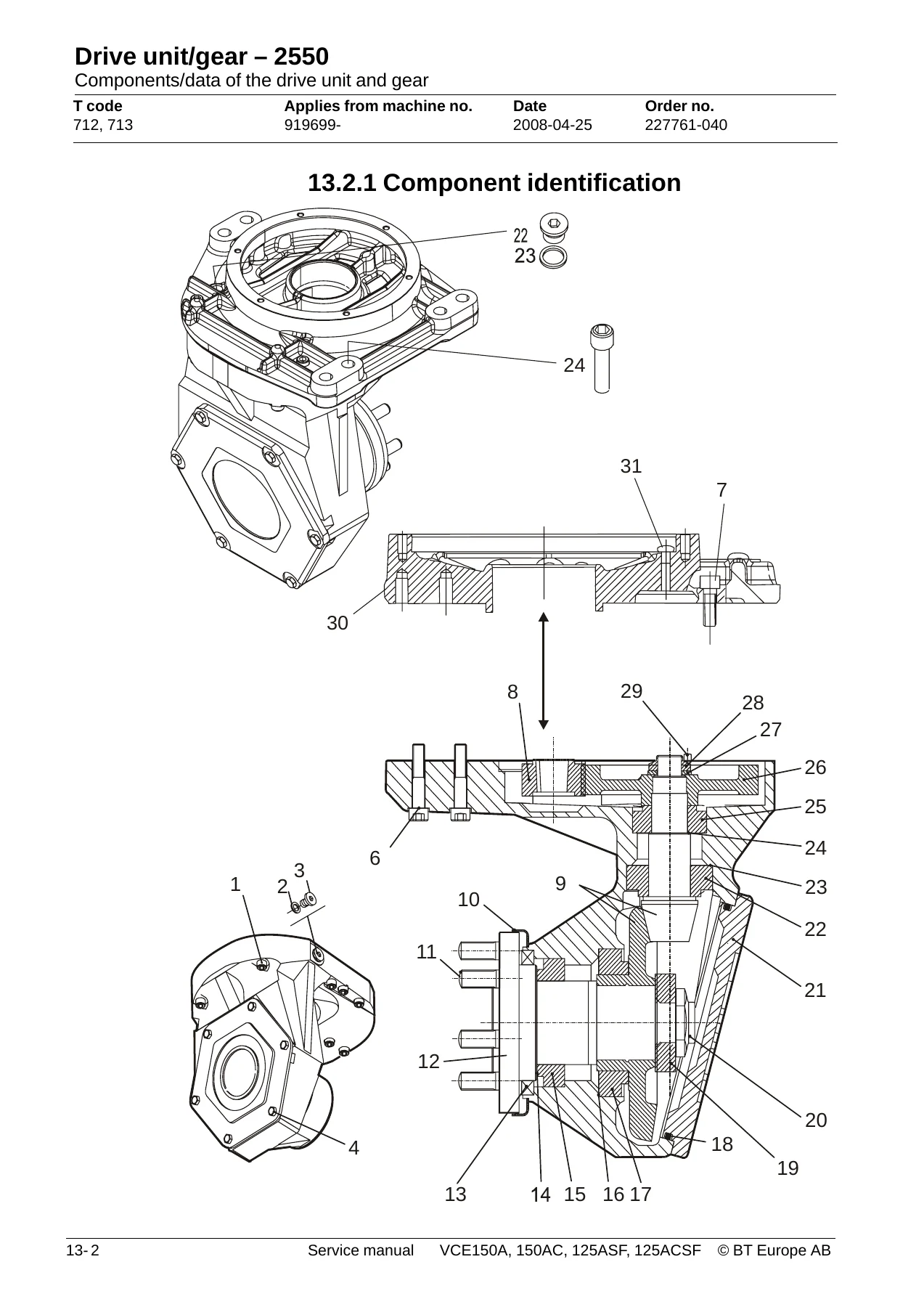
- Drive unit/gear – 2550
- Service brake system – 3100.1
- Service brake system – 3100.2
- Support arm brake – 3180
- Drive wheel – 3530
- Fork/support arm wheel – 3550
- Electrical system – 5000
- Hydraulic system – 6000
- Hydraulic pump – 6140
- Accumulators – 6280
- Main lift cylinder – 6610
- Main mast and mast – 7100
- Main lift chain system – 7120
- Initial mast – 7160
- Initial mast/Turret head fork unit – 7200 (T code 712)
- Shuttle fork – 7800 (T code 713)
- Wire guidance equipment – 8200
- Height preselection – 9390
Preventive Maintenance and Lubrication (P2, P3)
The preventive maintenance charts for both T code 712 and T code 713 are included, with inspection intervals at 250, 500, 1000, 2000 and 3000 hours plus 3, 6, 12, 24 and 36-month schedules. Each line item tells you what to inspect, tighten, clean, lubricate or measure – from battery locking devices and overhead guard mountings to greasable axle lubrication and gas strut strength. The P3 oil and grease specifications give ambient temperature ranges, viscosity classes and recommended products for chain lubrication, hydraulic oil, transmission oil and greases, with separate tables for T code 712 and T code 713. These two sections alone will keep your VCE150A or VCE125ASF on the correct service schedule.
Chassis and Frame Pivot (0000, 0320, 0400)
The chassis chapter walks through unloading a standing or lying-down truck, erecting it with cranes or counterweight trucks, final assembly, narrow-aisle installation, rail and wire guidance setup, and support arm collision guards. Detailed procedures cover removing and reassembling the rear chassis with pivot bearings, replacing the pivot bearings, and lowering the truck safely. The frame pivot section covers the greasable articulated centre axle with its recessed nipple and the tool kit required for replacement. The general tightening torque tables give dry and oiled values for galvanised and untreated bolts from M3 to M24.
Electric Motors and Drive Unit (1710.1, 1710.2, 1760, 2550)
Three motor sections cover the AC three-phase pump motor P112-195, the single-phase DC pump motor TTL 180C-P3A, and the AC three-phase drive motor D112-165. Each section explains dismantling, assembly, ball bearing replacement, shaft seal replacement and external temperature sensor mounting. The drive unit and gear chapter describes the 2-step angular gear with a 17.33:1 ratio, oil level checks, oil replacement intervals, drive shaft sealing ring replacement, top and lower cover leak repairs, and wheel bolt replacement. Motor mounting bolts, bearing bushes and gear components are all covered with their tightening torques.
Brake System (3100.1, 3100.2, 3180)
The service brake system chapters explain the three subsystems: regenerative motor braking, analogue electromechanical multiple disc brakes in the support arm wheels, and the single-stage electromechanical disc brake on the drive motor. You get functional descriptions, electromechanical disc brake assembly and dismantling, inspection, play adjustment (0.20-0.40 mm), wear limits, braking force testing with a torque wrench, and the multiple disc brake with support arms including shim adjustment. The support arm brake location chapter covers the outer and inner wheel positions and the interference issue with magnet sensors on earlier trucks.
Wheels (3530, 3550)
Drive wheel removal and assembly for the 350 x 130 mm wheel, including wheel nut torque of 130 Nm and Molykote grease application. The fork and support arm wheel chapter covers wheel dismantling with tool 08-13585, wheel bearing dismantling and assembly for the 300 mm wheel with brake and 350 mm wheel, sleeve nut torque of 50 Nm, and the support arm wheel axle shim procedure.
Electrical System (5000)
This is the largest single chapter in the manual, covering the Main Computer Unit (MCU A5), Fork Computer Unit (FCU A4), Integrated Control Panel (ICP A16), AC regulators (ACTL A1, ACTR A31, ACH A2), DC regulator DCHI (A32), parameters, diagnostics, error codes, wiring diagrams for T code 712 and T code 713, component lists, cabling contacts and functional descriptions. You will find log-in and start-up procedures, emergency driving mode, travel speed selection, steering, braking, hydraulic function monitoring, slack chain guards, height measurement, cabin lifting and lowering, special height functions, turret head auto rotation, shuttle fork traversing, wire guidance, display modes and calibration procedures. Warning and error codes are grouped by system: ICP, MCU, drive, cabin lift, steering, and fork unit systems. Hand-held terminal 1307 usage is also explained.
Hydraulic System (6000, 6140, 6280, 6610)
The hydraulic chapters cover two separate systems – cabin lifting with the AC pump motor, and initial lifting, turret head fork unit operation and steering with the DC pump motor. You get hydraulic flow diagrams for cabin lifting, the B cylinder system, the DC system for T code 712 and the diagram for T code 713, plus the extra hydraulic function. The hydraulic pump chapter gives max flow of 60 litres per minute, dismantling and assembly procedures. Accumulator charging covers both lifting and steering accumulators with pressure measurement, nitrogen charging and country-specific adapter kits. Main lift cylinder seal replacement in the B cylinder is fully described with the V10-16169 tool kit.
Masts and Fork Units (7100, 7120, 7160, 7200, 7800)
Main mast and mast chapter covers setting cab stoppers and mast stoppers. The main lift chain system explains chain inspection for noise, rust, stiff links, bolt rotation, outline wear and stretching, plus cleaning, lubrication, chain adjustment for the main lift, cabin and initial mast. Initial mast chapter 7160 covers the bracket replacement to prevent hose abrasion. The initial mast and turret head fork unit chapter (7200, T code 712) covers mast assembly and disassembly, belt installation and replacement, belt tensioning checks, friction plate adjustment, fork parallelism measurement, hydraulic hose and electric cabling connections. The shuttle fork chapter (7800, T code 713) covers assembly, maintenance chart, lubrication, chain adjustment, replacing shuttle forks and fixing forks that come loose from the fork carriage holders.
Wire Guidance and Height Preselection (8200, 9390)
Wire guidance equipment chapter explains the generator (LDU-22 for 220 V and LDU-21 for 110 V), output current of 75 mA, frequency of 6.25 kHz, battery backup over 6 hours and maximum cable length of approximately 750 m. The height preselection chapter covers the optional function introduced in firmware 213017-008, MCU parameter 159, programming a level, collection level, leaving level, order picking level, erasing and changing programmed levels, and automatic operation for collecting, depositing and order picking.
Why This BT Service Manual Matters
Narrow-aisle trucks like the VCE150A, VCE150AC, VCE125ASF and VCE125ACSF operate in demanding warehouse environments where incorrect repair procedures or wrong torque values can lead to costly downtime, damaged racking or safety incidents. This manual gives you the exact procedures BT specifies: the 339 Nm drive unit bolts, the 130 Nm wheel nuts, the 0.20-0.40 mm brake play, the 250 bar accumulator pressure, the 17.33:1 gear ratio, the 60 L/min hydraulic pump flow. You get the correct oil and grease specifications for your ambient temperature, the preventive maintenance intervals that keep the truck reliable, and the wiring diagrams and error code tables that let you diagnose electrical faults without guesswork.
Every chapter is written for the technician who needs to get the job done: step-by-step dismantling and assembly sequences, inspection criteria, wear limits, adjustment values, special tool numbers, and safety warnings where they matter. Whether you are replacing a pump motor bearing, adjusting the support arm brake, tensioning a mast chain, calibrating the turret head, or troubleshooting a wire guidance fault, this manual has the information you need.
IMAGES PREVIEW
Instant PDF Delivery
This BT VCE150A VCE150AC VCE125ASF VCE125ACSF service manual is delivered as an instant PDF download – no shipping, no waiting. The file works on any device: Windows PC, Mac, tablet or smartphone. You can print individual pages for the workshop, search across the full document, and keep a permanent reference copy for your service team. Whether you maintain one truck or a fleet, this workshop repair PDF gives you the same technical depth as the original BT service documentation, ready to use immediately after checkout.
Reviews
There are no reviews yet.