★ TRUSTED BY 321,897+ PROFESSIONALS WORLDWIDE
🏒
Trusted Business
Verified & Licensed
πŸ›‘οΈ
Virus Free Files
100% Safe Downloads
πŸ”’
Secure Payment
SSL Protected
⚑
Instant Delivery
Available Immediately
Sale!

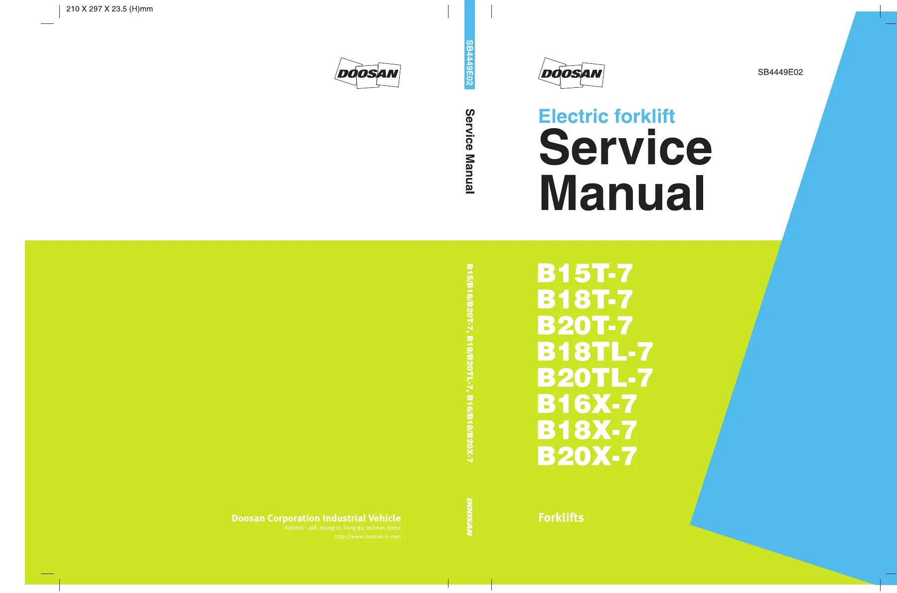
Doosan B15T-7 B18T-7 B20T-7 B18TL-7 B20TL-7 B16X-7 B18X-7 B20X-7 Electric Forklift Service Manual

Original price was: $44.95.Current price is: $26.95.

491-page Doosan electric forklift service manual for B15T-7, B18T-7, B20T-7, B18TL-7, B20TL-7, B16X-7, B18X-7 and B20X-7. Covers maintenance, electrical diagnosis, drive/brake, hydraulic, lift/tilt/auxiliary, steering, frame, fingertip controls and schematics. Document SB4449E02, July 2018.

⚑
Instant PDF Download
Available immediately
πŸ’Ύ
Save to Your Device
Download & keep forever
πŸ›‘οΈ
Antivirus Scanned
100% virus-free
🌍
Trusted Worldwide
175,000+ customers

Description

The Doosan B15T-7 B18T-7 B20T-7 B18TL-7 B20TL-7 B16X-7 B18X-7 B20X-7 Electric Forklift Service Manual is a 491-page service and repair reference for the Doosan electric forklift models B15T-7, B18T-7, B20T-7, B18TL-7, B20TL-7, B16X-7, B18X-7 and B20X-7. Identified as document SB4449E02 and dated July 2018, it explains the vehicle systems and provides service information for maintenance, diagnosis, testing, adjustment, removal, installation, disassembly and assembly. The manual is organized by forklift system so technicians can move from general service data into electrical, drive/brake, hydraulic, mast, steering, frame and fingertip-control work, then finish with hydraulic and electrical schematics.

Service Information for the B15/B18/B20 T, TL and X Series

This Doosan electric forklift service manual is built around the actual systems fitted to the covered trucks. The opening material gives exterior identification, model specifications, safety precautions, maintenance intervals, lubricant requirements, disassembly and assembly practices, standard fastener torques and fitting torques. From there, the manual develops each major system with component descriptions, operating explanations, checks, specifications and repair procedures.

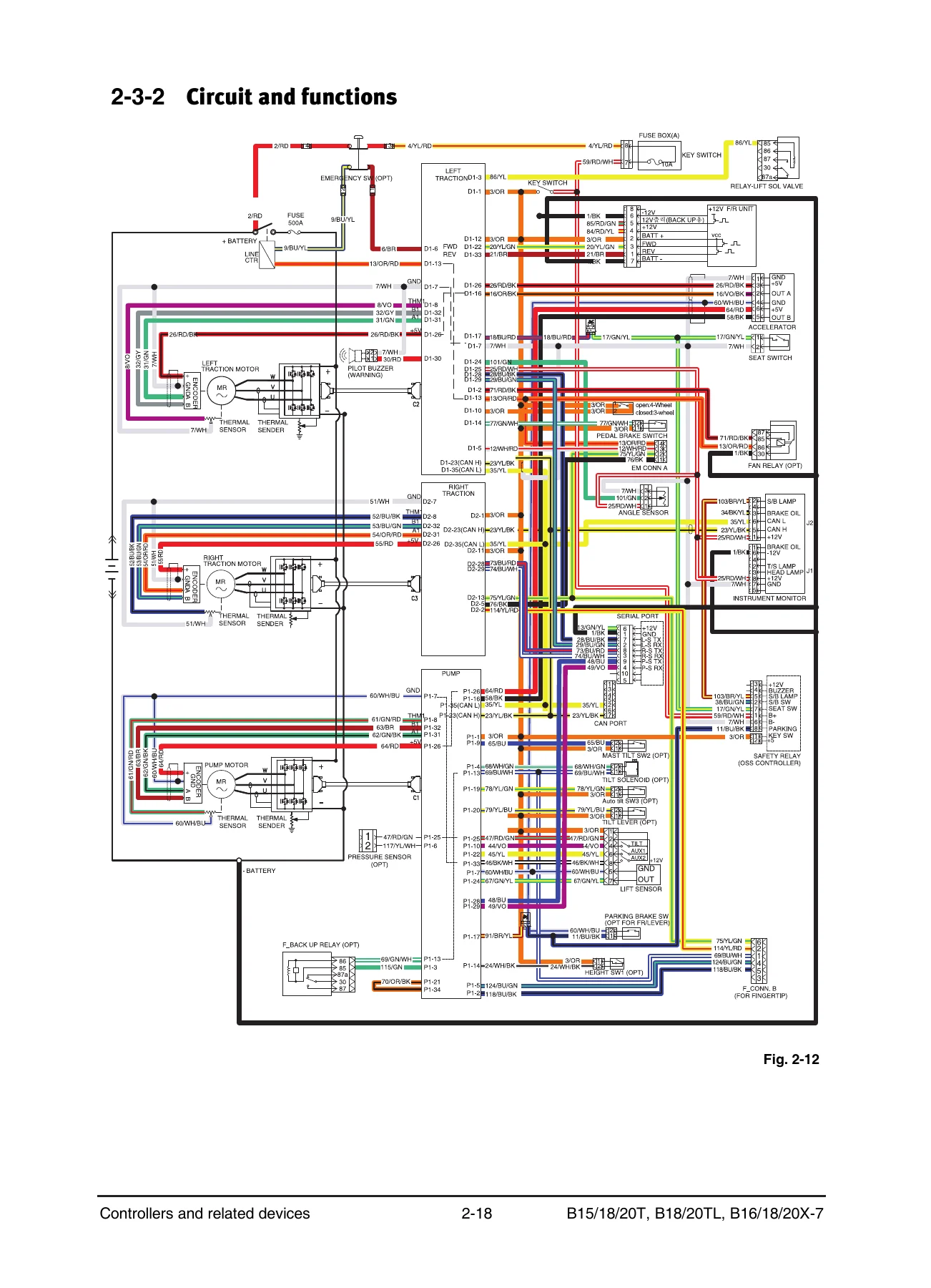
The electrical section is particularly detailed. It covers battery specifications and testing, controller circuits, CAN communication, fuse and DC-DC converter circuits, instrument-panel diagnosis and calibration, and the EasyView application used with CURTIS controllers. Fault-code information is included for tracing electrical and control-system problems, while wiring tables and circuit illustrations show how controllers, sensors, switches, relays, solenoids and loads are connected. The drive and hydraulic sections then carry the same service approach into motors, axles, brakes, pumps, valves and related components.

File Details

  • Manual type: Service Manual
  • Brand: Doosan
  • Models: B15T-7, B18T-7, B20T-7, B18TL-7, B20TL-7, B16X-7, B18X-7, B20X-7
  • Language: English
  • Page count: 491 pages
  • File format: PDF
  • Document number: SB4449E02
  • Revision date: Jul. 23, 2018

Maintenance, Testing and Diagnostic Coverage

The manual combines scheduled service information with system-level troubleshooting. Maintenance tables include daily or 10-hour checks and periodic inspections at 250, 500, 1,000 and 2,000 service-hour intervals, together with items inspected or replaced at those stages. Lubricant guidance covers hydraulic and power-steering oil, drive-axle oil, brake oil and grease, with viscosities, temperature ranges and refill capacities where specified.

Electrical diagnosis extends beyond basic continuity checks. The manual explains battery load and cell testing, controller LED fault-code indication, instrument-panel diagnostic codes and calibration parameters, and EasyView test and calibration menus. Procedures also cover controller firmware updating, parameter handling, initial accelerator, lift-sensor and steering-sensor settings, and fault handling. This makes the Doosan B15T-7 B18T-7 B20T-7 B18TL-7 B20TL-7 B16X-7 B18X-7 B20X-7 Electric Forklift Service Manual useful when a fault involves the interaction of electronic controls with traction, pump, steering or hydraulic functions rather than a single mechanical component.

Chapters Covered

  • 1 General
    • How to use this manual and warning label definitions
    • Glossary
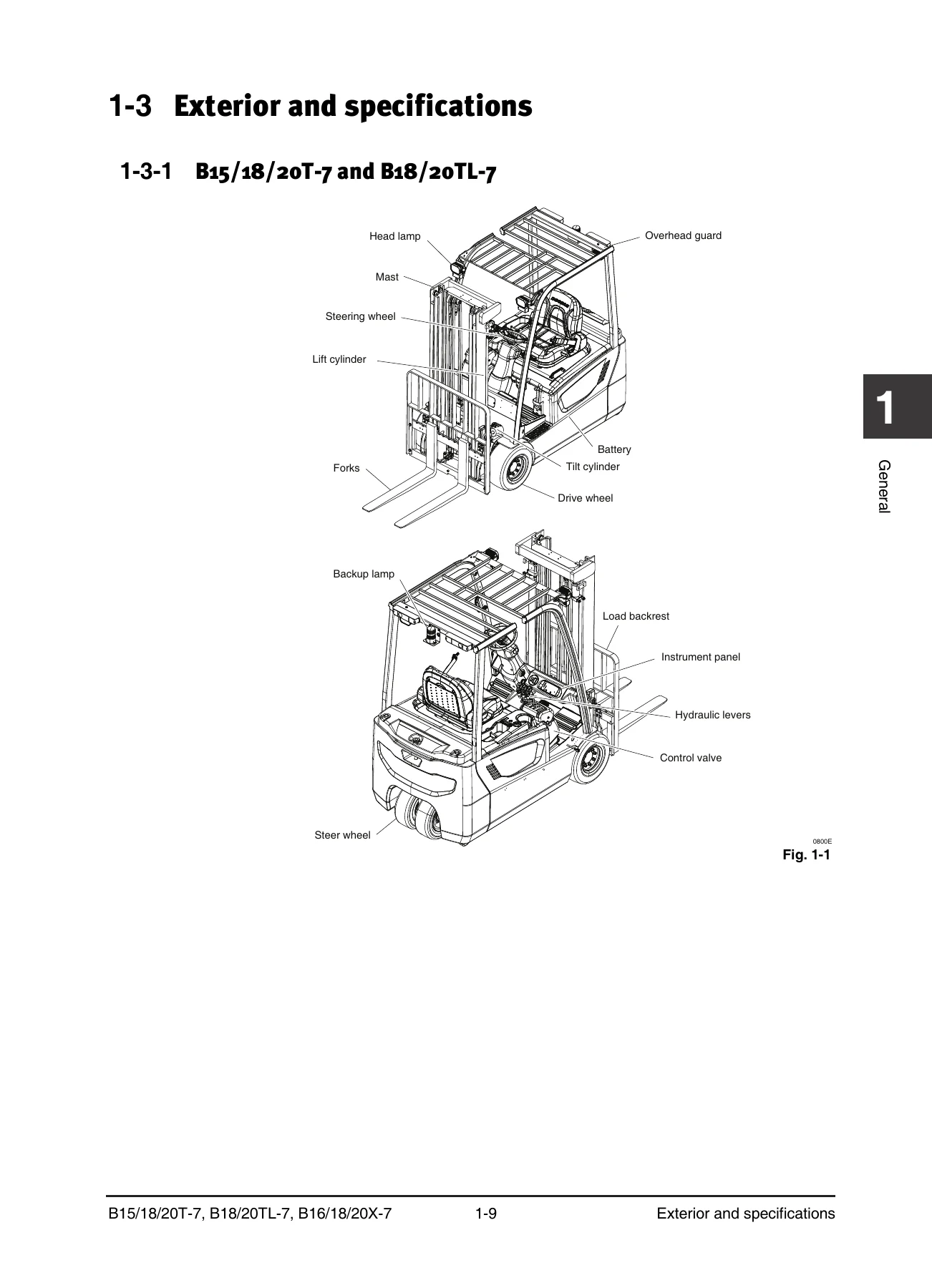
    • Exterior and specifications for B15/18/20T-7, B18/20TL-7 and B16/18/20X-7
    • Safety precautions
    • Maintenance
    • Lubricants, recommended viscosities and capacities
    • Disassembly/assembly instructions
    • Standard torques for bolts, nuts and fittings
  • 2 Electrical System
    • Overview, components and CAN communication protocol
    • Battery specifications, functions, wiring, testing, maintenance, removal and installation
    • Controllers and related devices: circuits, wiring, LED fault codes, tests, removal and installation
    • Fuse box, DC-DC converter, lamp group, OSS controller and horn
    • Instrument panel display, diagnosis and calibration
    • EasyView installation, firmware update, diagnostic parameters, calibration parameters and initial settings
    • Handling faults on the instrument panel and EasyView
  • 3 Drive/Brake System
    • Drive motor specifications, operation, removal/installation, disassembly/assembly and test
    • Drive wheel removal/installation
    • Drive axle specifications, operation, oil replacement, adjustment, disassembly and assembly
    • Accelerator specifications, operation, removal and installation
    • F/R unit specifications, operation and removal/installation
    • Service brake pedal assembly, adjustment, brake-oil air removal and master-cylinder service
    • EM parking brake operation, testing and manual release
    • Driving, service-brake and EM parking-brake troubleshooting
  • 4 Hydraulic System
    • System components and oil flow
    • Pump motor specifications, operation, removal/installation, disassembly/assembly and test
    • Main hydraulic pump specifications, operation, removal and installation
    • Priority valve specifications, operation, removal, disassembly and assembly
    • Hydraulic tank and filter, including oil and filter replacement
    • Hydraulic troubleshooting
  • 5 Lift/Tilt/Auxiliary System
    • Components and oil flow
    • Control valve operation, relief-valve adjustment, emergency lowering, lever/switch adjustment and valve service
    • Mast assembly specifications and operation
    • Fork, sideshifter and chain service
    • Tilt-cylinder, primary lift-cylinder and standard/secondary-cylinder service
    • Carriage and mast service
    • GSS and auto-tilt leveling options
    • Lift/tilt/auxiliary troubleshooting
  • 6 Steering System
    • Components and oil flow
    • Steering control group specifications, operation, air removal and pressure checks
    • Steering wheel, column and steering-unit service
    • Steering operation group for B15/18/20T (TL) models
    • Steering operation group for B16/18/20X models
    • Steer-angle sensor, rear wheel/hub, axle, link, knuckle, king pin, bearing and steering-cylinder procedures
    • Steering troubleshooting
  • 7 Frame
    • Hood removal/installation
    • Overhead guard removal/installation
    • Floor plates removal/installation
    • Top cover and counterweight removal/installation
  • 8 Fingertip Option
    • Fingertip extension module and armrest unit
    • Control valve – Kayaba (-Jul. 2018): wiring, operation, relief adjustments, manual lowering and service
    • Control valve – Walvoil (Jul. 2018-): wiring, operation, relief adjustments, manual lowering and service
    • Steering pressure switch assembly and pump-motor operation at steering
    • Fault display and troubleshooting
  • 9 Schematics
    • Hydraulic schematic
    • Hydraulic schematic with fingertip
    • Electrical schematic

Across these chapters, the manual ties system descriptions to the actual service work: identifying components, understanding how circuits and mechanisms operate, checking measurements, following removal and installation sequences, carrying out adjustments, and using troubleshooting information when symptoms need to be isolated. Detailed drawings and schematics support work on the traction motors and controllers, drive axle and brakes, hydraulic pump and control valve, mast and cylinders, steering hardware and optional fingertip controls.

Repair Procedures, Specifications and Schematics in One Manual

The general data section gives model-specific dimensions and performance information, battery arrangements, motor ratings and hydraulic relief-pressure information. Service sections add component specifications, test values, torque data, adjustment values and procedure-specific installation information. The schematics section provides hydraulic, fingertip-hydraulic and electrical circuit references, making it easier to follow a system from input or power source through controls to the operating component.

For technicians working on the covered Doosan B15T-7, B18T-7, B20T-7, B18TL-7, B20TL-7, B16X-7, B18X-7 or B20X-7 forklift, this manual supports a wide range of maintenance, diagnostic and repair jobs without relying on generic procedures for a different truck family. It also clearly separates model groups where steering, chassis or equipment details differ.

Complete PDF Bookmark Tree

Complete Bookmarks

The complete bookmarks in the β€œDoosan B15T-7 B18T-7 B20T-7 B18TL-7 B20TL-7 B16X-7 B18X-7 B20X-7 Electric Forklift Service Manual” are as follows:

B15T-7_SB4449E02p. 1
Forewordp. 2
Table of contentsp. 3
1 Generalp. 4
1-1 How to use this manualp. 5
1-1-1 Construction of this manualp. 5
1-1-2 Warning label definitionp. 7
1-2 Glossaryp. 8
1-3 Exterior and specificationsp. 12
1-3-1 B15/18/20T-7 and B18/20TL-7p. 12
1-3-2 B16/18/20X-7p. 18
1-4 Safety precautionsp. 22
1-5 Maintenancep. 29
1-6 Lubricantsp. 33
1-6-1 Recommended viscosities and capacitiesp. 33
1-6-2 Lubricant specificationsp. 34
1-7 Disassembly/assembly instructionsp. 38
1-8 Standard torquesp. 47
1-8-1 Standard torques for bolts and nutsp. 47
1-8-2 Standard torques for tightening fittingsp. 49
2 Electrical systemp. 53
2-1 Overviewp. 54
2-1-1 Componentsp. 54
2-1-2 Communication protocolp. 56
2-2 Batteryp. 58
2-2-1 Exterior and specificationsp. 58
2-2-2 Functionsp. 60
2-2-3 Wiringp. 62
2-2-4 Testp. 63
2-2-5 Maintenancep. 66
2-2-6 Removal and installationp. 68
2-3 Controllers and related devicesp. 69
2-3-1 Exterior and specificationsp. 69
2-3-2 Circuit and functionsp. 70
2-3-3 Wiringp. 72
2-3-4 LED fault codesp. 75
2-3-5 Testp. 76
2-3-6 Removal and installationp. 78
2-4 Miscellaneous loadsp. 81
2-4-1 Fuse boxp. 81
2-4-2 DC-DC converterp. 84
2-4-3 Lamp groupp. 87
2-4-4 OSS controllerp. 88
2-4-5 Hornp. 90
2-5 Instrument panelp. 91
2-5-1 Display and buttonsp. 91
2-5-2 Diagnosisp. 96
2-5-3 Calibrationp. 100
2-6 Application β€œEasyView”p. 106
2-6-1 Installation and executionp. 106
2-6-2 Controller firmware updatep. 112
2-6-3 β€œAdministration” menu descriptionp. 116
2-6-4 β€œTools” menu descriptionp. 117
2-6-5 Main page – Test Menu (diagnostic parameters)p. 125
2-6-6 Main page – Calibration Menu (calibration parameters)p. 132
2-6-7 Initial settingsp. 151
2-7 Handling faults on instrument panel/EasyViewp. 155
3 Drive-brake systemp. 176
3-1 Overviewp. 177
3-1-1 Componentsp. 177
3-2 Drive motorp. 179
3-2-1 Exterior and specificationsp. 179
3-2-2 How it worksp. 181
3-2-3 Drive motor/axle/EM brake removal/installationp. 183
3-2-4 Drive motor disassembly/assembly and testp. 185
3-2-5 Drive wheel removal/installationp. 187
3-3 Drive axlep. 188
3-3-1 Exterior and specificationsp. 188
3-3-2 How it worksp. 189
3-3-3 Drive axle oil replacementp. 192
3-3-4 Adjustmentp. 193
3-3-5 Disassembly and assemblyp. 194
3-4 Acceleratorp. 199
3-4-1 Exterior and specificationsp. 199
3-4-2 How it worksp. 200
3-4-3 Removal and installationp. 201
3-5 F/R unitp. 202
3-5-1 Exterior and specificationsp. 202
3-5-2 How it worksp. 203
3-5-3 Removal/Installationp. 205
3-6 Service brake pedal ass’yp. 206
3-6-1 Exterior and specificationsp. 206
3-6-2 How it worksp. 207
3-6-3 Brake pedal adjustmentp. 211
3-6-4 Air removal in brake oilp. 212
3-6-5 Brake pedal ass’y removal/installationp. 214
3-6-6 Master cylinder disassembly/assemblyp. 216
3-7 EM parking brakep. 217
3-7-1 Exterior and specificationsp. 217
3-7-2 How it worksp. 218
3-7-3 Parking brake testp. 219
3-7-4 Manual release of brakingp. 220
3-8 Troubleshootingp. 221
3-8-1 Drivingp. 221
3-8-2 Service brakep. 223
3-8-3 EM parking brakep. 224
4 Hydraulic systemp. 225
4-1 Overviewp. 226
4-1-1 Componentsp. 226
4-1-2 Oil flowp. 228
4-2 Pump motorp. 230
4-2-1 Exterior and specificationsp. 230
4-2-2 How it worksp. 232
4-2-3 Pump motor and main hydraulic pump removal/installationp. 234
4-2-4 Pump motor disassembly/assembly and testp. 236
4-3 Main hydraulic pumpp. 238
4-3-1 Exterior and specificationsp. 238
4-3-2 How it worksp. 239
4-3-3 Removal and installationp. 240
4-4 Priority valvep. 242
4-4-1 Exterior and specificationsp. 242
4-4-2 How it worksp. 243
4-4-3 Removal and installationp. 244
4-4-4 Disassembly and assemblyp. 245
4-5 Hydraulic tank and filterp. 246
4-5-1 Exterior and specificationsp. 246
4-5-2 How it worksp. 248
4-5-3 Hydraulic oil and filter replacementp. 250
4-6 Troubleshootingp. 251
5 Lift systemp. 252
5-1 Overviewp. 253
5-1-1 Componentsp. 253
5-1-2 Oil flowp. 255
5-2 Control valvep. 257
5-2-1 Exterior and specificationsp. 257
5-2-2 How it worksp. 258
5-2-3 Relief valve adjustmentp. 269
5-2-4 Needle valve for emergent loweringp. 271
5-2-5 Levers and switch group adjustment/removal/installationp. 273
5-2-6 Control valve removal/installationp. 275
5-2-7 Control valve disassembly/assemblyp. 277
5-3 Mast ass’yp. 279
5-3-1 Exterior and specificationsp. 279
5-3-2 How it worksp. 281
5-3-3 Forks servicep. 289
5-3-4 Sideshifter servicep. 291
5-3-5 Chains servicep. 297
5-3-6 Tilt cylinders servicep. 303
5-3-7 Primary lift cylinders servicep. 311
5-3-8 Standard/secondary cylinders servicep. 315
5-3-9 Carriage servicep. 325
5-3-10 Mast servicep. 329
5-4 GSS and auto-tilt leveling optionsp. 335
5-4-1 Exterior and specificationsp. 335
5-4-2 How it worksp. 337
5-4-3 Height switch removal/installationp. 340
5-4-4 Mast tilt/auto-tilt switch ass’y removal/installationp. 341
5-4-5 Hydraulic block ass’y removal/installationp. 343
5-5 Troubleshootingp. 345
6 Steering systemp. 347
6-1 Overviewp. 348
6-1-1 Componentsp. 348
6-1-2 Oil flowp. 350
6-2 Steering control groupp. 352
6-2-1 Exterior and specificationsp. 352
6-2-2 How it worksp. 354
6-2-3 Steering system air removalp. 361
6-2-4 Steering system pressure checkp. 362
6-2-5 Steering wheel cover removal/installationp. 364
6-2-6 Steering wheel removal/installationp. 365
6-2-7 Steering wheel column removal/installationp. 366
6-2-8 Steering unit disassembly/assemblyp. 368
6-3 Steering operation group [B15/18/20T (TL)]p. 370
6-3-1 Exterior and specificationsp. 370
6-3-2 How It worksp. 372
6-3-3 Steer angle sensor removal/installationp. 374
6-3-4 Rear wheel and hub adjustment/removal/installationp. 375
6-3-5 Steer axle spindle removal/installation/disassembly/assemblyp. 378
6-3-6 Steer axle housing ass’y disassembly/assemblyp. 380
6-4 Steering operation group [B16/18/20X]p. 382
6-4-1 Exterior and specificationsp. 382
6-4-2 How it worksp. 384
6-4-3 Steer angle sensor removal/installationp. 386
6-4-4 Rear wheel and hub adjustment/removal/installationp. 387
6-4-5 Steer axle removal/installationp. 390
6-4-6 Link ass’y removal/installationp. 392
6-4-7 Steering knuckle, king pin, and bearing removal/installationp. 393
6-4-8 Steering cylinder removal/installation/disassembly/assemblyp. 394
6-5 Troubleshootingp. 396
7 Framep. 398
7-1 Hood removal/installationp. 399
7-2 Overhead guard removal/installationp. 401
7-3 Floor plates removal/installationp. 402
7-4 Top cover and counterweightremoval/installationp. 403
8 Fingertipp. 405
8-1 Overviewp. 406
8-1-1 Components and circuitp. 406
8-2 Fingertip extension modulep. 408
8-2-1 Exterior and specificationsp. 408
8-2-2 Circuit configuration and key functionsp. 409
8-2-3 Wiringp. 410
8-2-4 Removal and installationp. 411
8-3 Fingertip armrest unitp. 412
8-3-1 Exterior and specificationsp. 412
8-3-2 Circuit configuration and key functionsp. 414
8-3-3 Circuit configuration and key functionsp. 415
8-3-4 Hydraulic control knobsp. 416
8-3-5 Forward/reverse switchp. 417
8-3-6 Removal and installationp. 418
8-3-7 Disassembly and assemblyp. 419
8-4 Control valve – Kayaba (–Jul. 2018)p. 423
8-4-1 Exterior and specificationsp. 423
8-4-2 Wiringp. 425
8 -4-3 How it worksp. 426
8-4-4 Relief valve adjustmentsp. 438
8-4-5 Manual loweringp. 442
8-4-6 Removal and installationp. 443
8-4-7 Disassembly and assemblyp. 444
8-5 Control valve – Walvoil (Jul. 2018–)p. 445
8-5-1 Exterior and specificationsp. 445
8-5-2 Wiringp. 447
8-5-3 How it worksp. 448
8-5-4 Relief valve adjustmentsp. 460
8-5-5 Manual loweringp. 462
8-5-6 Disassembly and assemblyp. 463
8-6 Steering pressure switch ass'yp. 465
8-6-1 Exterior and specificationsp. 465
8-6-2 Wiringp. 465
8-6-3 Pump motor operation at steeringp. 466
8-7 Fault diagnosisp. 468
8-7-1 Fault displayp. 468
8-7-2 Troubleshootingp. 469
9 Schematicsp. 483
Hydraulic Schematicp. 484
Hydraulic Schematic – Fingertip Option – Kayaba (–Jul. 2018)p. 485
Hydraulic Schematic – Fingertip Option – Walvoil (Jul. 2018–)p. 486
Electric Schematicp. 487
Indexp. 488
Revision historyp. 491

Get the Doosan B15T-7 B18T-7 B20T-7 B18TL-7 B20TL-7 B16X-7 B18X-7 B20X-7 Electric Forklift Service Manual

IMAGES PREVIEW

Doosan B15T-7 B18T-7 B20T-7 B18TL-7 B20TL-7 B16X-7 B18X-7 B20X-7 Electric Forklift Service Manual β€” PDF page 1 preview
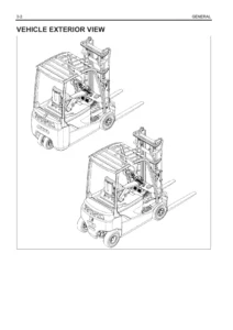
Doosan B15T-7 B18T-7 B20T-7 B18TL-7 B20TL-7 B16X-7 B18X-7 B20X-7 Electric Forklift Service Manual β€” PDF page 12 preview
Doosan B15T-7 B18T-7 B20T-7 B18TL-7 B20TL-7 B16X-7 B18X-7 B20X-7 Electric Forklift Service Manual β€” PDF page 70 preview

Use this manual to diagnose faults, service electrical and hydraulic systems, remove and install major components, carry out adjustments, disassemble and assemble serviceable units, and reference the correct procedures, specifications, torque data and schematics for the covered trucks. Working from model-specific service information helps reduce guesswork when a repair depends on correct values, component sequence or circuit routing. Your purchase is delivered as an instant PDF download after payment, with no physical shipping required. The PDF can be opened on compatible phones, tablets and computers and pages can be printed when you need a workshop copy beside the forklift.
Reviews

There are no reviews yet.

Be the first to review “Doosan B15T-7 B18T-7 B20T-7 B18TL-7 B20TL-7 B16X-7 B18X-7 B20X-7 Electric Forklift Service Manual”

What Our Customers Say

β˜…β˜…β˜…β˜…β˜… Live reviews from customers
Loading customer reviews...
0
    0
    Your Cart
    Your cart is emptyReturn to Shop
    πŸ›’
    Recently Purchased
    πŸ•’ verified order