
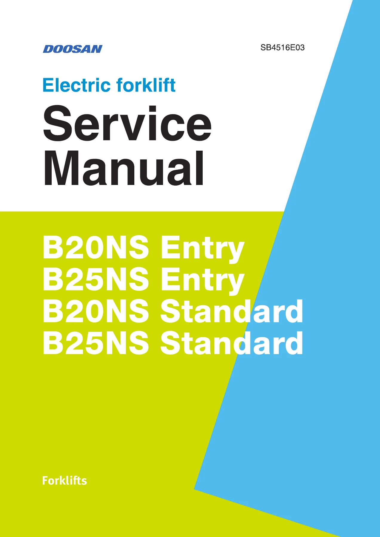
Doosan B30/35NS Electric Forklift Service Manual SB4516E03 PDF
Original price was: $44.95.$26.95Current price is: $26.95.
A 568-page Doosan B30/35NS electric forklift service manual covering electrical diagnostics, drive and brake service, hydraulics, steering, lift/tilt/auxiliary systems, frame work, fingertip controls, battery and charger service, fault-code troubleshooting, calibration, and hydraulic/electrical schematics. Document number SB4516E03.
Description
Doosan B30/35NS Electric Forklift Service Manual SB4516E03 PDF
The Doosan B30/35NS Electric Forklift Service Manual SB4516E03 PDF is a 568-page service reference covering the vehicle systems, disassembly and assembly work, testing, adjustments, diagnostics, troubleshooting and schematics used for B30/35NS electric forklifts. The foreword identifies the manual as service information for DOOSAN forklift models B30/35NS and explains that it is intended to help service personnel understand and repair the vehicle correctly. The manual is organized by system, allowing technicians to move from general service data into electrical, drive and brake, hydraulic, steering, mast and attachment, frame, fingertip-control, battery and charger, and schematic information.
File Details
- Manual type: Electric forklift service manual
- Brand / model: Doosan B30/35NS
- Language: English
- Page count: 568 pages
- File format: PDF
- Document number: SB4516E03
- Revision history: SB4516E03 entries dated Oct. 2021 and Apr. 2022
Coverage Note for B30/35NS
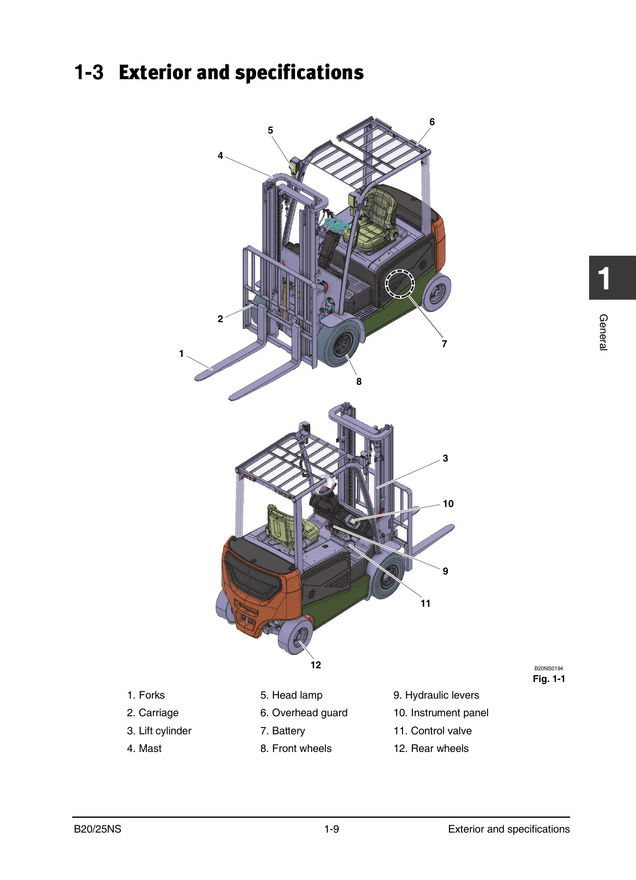
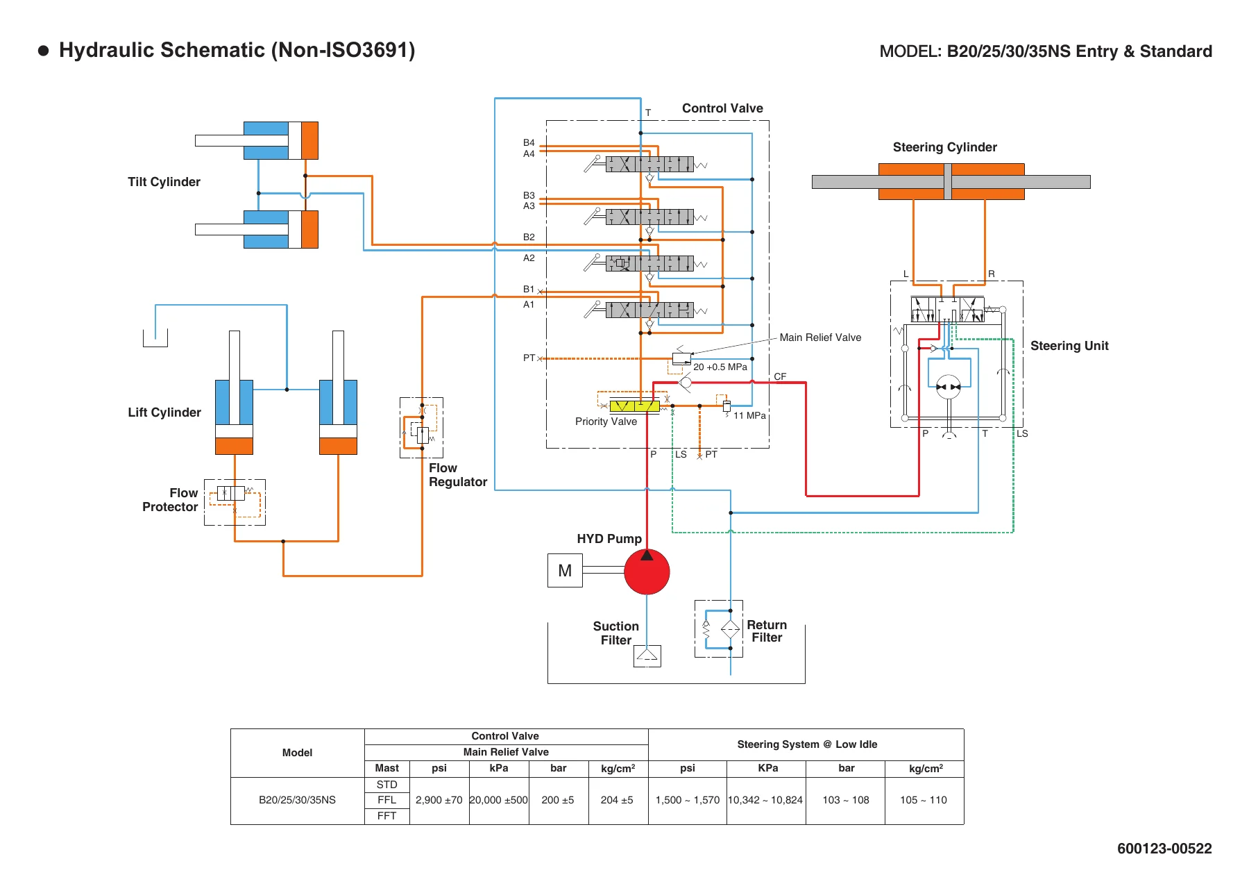
The manual identifies B30/35NS in its foreword and contains B30/35NS-specific 80 V information, including model selection information for Entry and Standard configurations and an 80 V fingertip extension module application. Some shared service sections, illustrations and page footers are marked B20/25NS, while the hydraulic schematics identify B20/25/30/35NS Entry and Standard models. This reflects shared NS-series service material within the document and is important when following model-dependent electrical or component information.
Chapters Covered
- General: how to use the manual; glossary; exterior and specifications; safety precautions; maintenance; lubricants and recommended viscosities; disassembly and assembly instructions; standard torques for bolts, nuts and fittings.
- Electrical System: electrical system configuration and CAN communication; lead storage battery; emergency switch; controllers and related devices; fuse box, DC-DC converter, lamps, OSS and horn; Entry and Standard instrument panels; EasyView diagnosis and calibration; fault-code troubleshooting.
- Drive/Brake System: components; drive motor specifications, operation, removal and disassembly; transaxle operation, oil change and service; accelerator; F/R unit; brake pedal; Standard-truck electromagnetic parking brake; Entry-truck parking brake; troubleshooting.
- Hydraulic System: components and oil flow; pump motor; main hydraulic pump; hydraulic tank and filter; filter and hydraulic-oil changes; troubleshooting.
- Steering System: components and oil flow; steering control group; steering-system air removal and pressure check; steering wheel and column service; steering operation group; steering-angle sensor setting; steer axle and steering cylinder service; troubleshooting.
- Lift/Tilt/Auxiliary System: components and oil flow; non-ISO3691 and ISO3691 control valves; manual lowering; pressure check and main relief-valve adjustment; control-valve removal and disassembly; mast assembly; forks, sideshifter, chains, tilt cylinders, lift cylinders, carriage and mast service; troubleshooting.
- Frame: hood removal and installation; overhead-guard removal and installation; counterweight removal and installation.
- Fingertip Option: electrical and hydraulic circuits; fingertip extension module; armrest unit; fingertip control valve; relief-valve adjustment and manual lowering; steering pressure switch; priority and locking valves; jumper harness; fault display and troubleshooting.
- Battery and Charger: lithium phosphate battery specifications, structure, precautions, display, errors, troubleshooting and parts replacement; lithium phosphate charger technical parameters and operation; lead battery specifications, use, maintenance, disassembly and troubleshooting; lead charger specifications, operation and troubleshooting.
- Schematics: hydraulic schematics for non-ISO3691, ISO3691 and fingertip configurations; electrical schematics for Entry and Standard trucks; fingertip electrical schematic; jumper-harness drawing.
Taken as a whole, the Doosan B30/35NS electric forklift service manual moves from basic service preparation and scheduled maintenance into system operation, component testing, removal and installation, disassembly and assembly, calibration and fault diagnosis. It also gives technicians the diagrams and service data needed to trace electrical and hydraulic functions rather than relying only on symptom descriptions.
Electrical Diagnosis, Controllers and Calibration
A major part of the Doosan B30/35NS Electric Forklift Service Manual SB4516E03 PDF is dedicated to the electrical system. The manual explains the relationship between the battery, emergency switch, drive and pump controllers, sensors, switches, relays, actuators, fuse box, DC-DC converter and instrument panel. CAN communication is described as the data-sharing protocol between controllers and instrument devices, and the manual includes circuit diagrams showing how the major electrical devices communicate.
Controller service coverage includes connector pin information, circuit operation, LED fault-code indication, electrical tests, control-panel access and controller removal and installation. The manual also covers both Entry and Standard instrument panels, including status indicators, diagnostic functions, calibration functions and fault displays. For deeper service work, the EasyView section explains vehicle connection, diagnostic monitoring, parameter handling, controller firmware procedures, data logging, fault history, cloning and initial settings for the accelerator, lift sensor and steering sensor.
The fault-code section goes beyond a simple code list. It defines fault levels and then provides fault descriptions, possible causes and service measures for controller, CAN communication, battery voltage, encoder, thermal sensor, accelerator, seat-switch, solenoid and other electrical-system faults. This makes the Doosan B30/35NS service manual particularly useful when a truck powers up but reports a controller or system fault that requires structured diagnosis.
Drive, Brake, Hydraulic and Steering Repair Information
The drive and brake chapter covers the drive motor, transaxle, accelerator and forward/reverse control, followed by brake-pedal and parking-brake service for the different truck configurations. Procedures include component removal and installation, transaxle oil service, drive-wheel work, drive-axle and transmission assembly work, parking-brake testing and adjustment, and system troubleshooting.
Hydraulic coverage starts with component layout and oil flow before moving into the pump motor, main pump, hydraulic tank and filters. The manual includes service procedures for pump-motor and pump removal, disassembly and assembly, hydraulic-filter replacement and hydraulic-oil replacement. The steering chapter then follows the oil path through the steering system and provides checks and service procedures for the steering control group, steering wheel and column, steering angle sensor, steer axle and steering cylinder. Air removal and steering-system pressure checks are included for diagnosing hydraulic steering problems.
Mast, Forks, Cylinders and Auxiliary Functions
The lift, tilt and auxiliary chapter is one of the most repair-oriented sections in the manual. It covers control valves used with non-ISO3691 and ISO3691 configurations, explains valve operation and port identification, and provides manual-lowering and main relief-pressure check and adjustment procedures. Control-valve removal, installation, disassembly and assembly are followed by extensive mast service information.
Mast-system procedures cover forks, sideshifter, chains, tilt cylinders, primary lift cylinders, standard and secondary cylinders, carriage and mast components. The manual combines operational explanations with removal and installation steps, checks, adjustment information and troubleshooting. For trucks equipped with fingertip controls, a separate chapter details the electrical and hydraulic architecture of the option, including the extension module, armrest controls, control valve, steering pressure switch, locking valves and related fault diagnosis.
Maintenance Data, Lubrication and Workshop Procedures
General service information includes safety precautions, maintenance checks, lubricant selection, recommended viscosities and capacities, disassembly and assembly practices and standard tightening torques. The maintenance material addresses inspections at different service intervals and includes checks for the battery, mast, chains, hydraulic system, steering-related parts, wheels, parking brake and other service points. The lubrication section identifies hydraulic-oil grades, drive-axle oil requirements, chain and linkage oils and grease guidance.
The disassembly and assembly chapter provides practical workshop guidance for cleaning, handling bearings and seals, installing press-fitted parts, working with O-rings and gaskets, routing hydraulic lines and tightening fittings. Standard torque tables cover metric and inch fasteners along with multiple fitting styles. These details support correct reassembly after major component service and help reduce errors caused by incorrect fasteners, damaged seals or improperly tightened hydraulic connections.
Battery, Charger and Schematic Reference
The battery and charger chapter includes both lithium phosphate and lead-battery material. Lithium coverage includes specifications, internal structure, precautions, connection and use, display functions, error information, troubleshooting and spare-parts replacement, together with charger parameters, operation and maintenance information. Lead-battery coverage includes specifications, major components, installation precautions, operation, regular maintenance, disassembly and assembly, fault diagnosis and charger service.
The final schematics section is valuable when tracing a fault across systems. It contains hydraulic drawings for non-ISO3691, ISO3691 and fingertip-control configurations, plus electrical drawings for Entry, Standard and fingertip-equipped trucks. The hydraulic drawings explicitly identify B20/25/30/35NS Entry and Standard applications, allowing the technician to relate hydraulic supply, steering and mast functions to the wider system layout.
Use This Manual for Correct B30/35NS Service Work
The Doosan B30/35NS Electric Forklift Service Manual SB4516E03 PDF supports maintenance, electrical diagnosis, fault-code investigation, controller and sensor checks, drive and brake service, hydraulic and steering repairs, mast and cylinder work, fingertip-control diagnosis, battery and charger service, and schematic tracing. Having the procedures, system explanations, service checks, adjustment information and diagrams together helps technicians work from the correct sequence and specifications instead of relying on guesswork during repair.
Purchase provides instant PDF delivery with no physical shipping. The manual can be opened on compatible phones, tablets and computers and can be printed when a paper workshop reference is preferred.
IMAGES PREVIEW
Reviews
There are no reviews yet.