
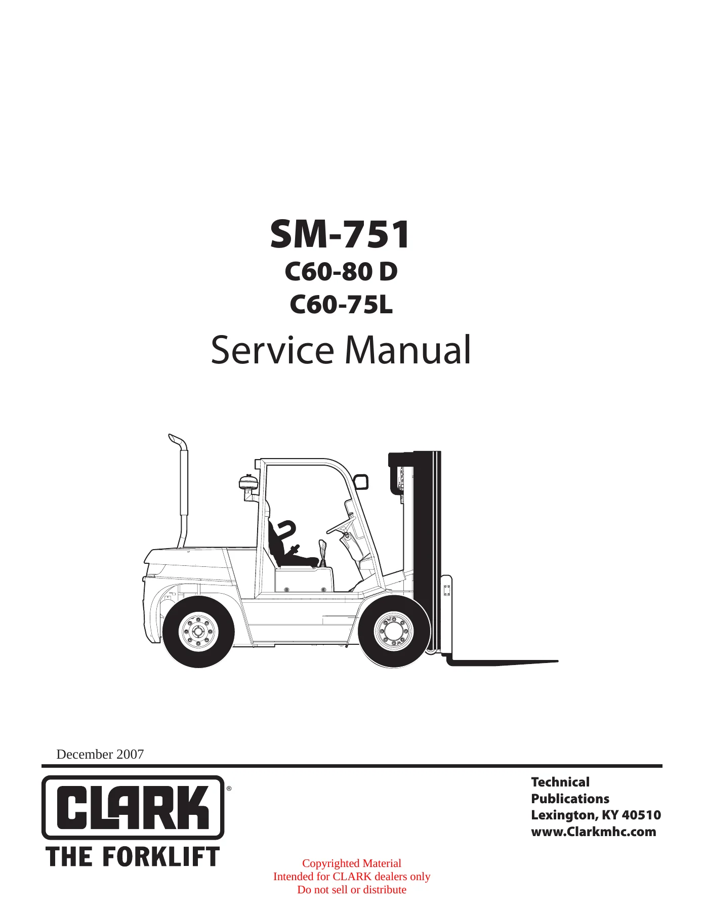
Clark C60 C70 C80 C60-75L Service Manual SM-751 – Complete Forklift Workshop Repair Guide
Original price was: $39.95.$23.95Current price is: $23.95.
The complete Clark SM-751 Service Manual for C60-80D and C60-75L forklifts. Nearly 800 pages of factory repair, diagnostic, and overhaul procedures for diesel and LPG models, covering every major system from engine to upright.
Description
File Details
- Manual Type: Complete Service Manual
- Document Number: SM-751
- Brand: Clark
- Models Covered: C60-80D, C60-75L
- Engine Options: IVECO NEF Diesel, GM V6 4.3L LPG
- Language: English
- Page Count: Approximately 802 pages
- File Format: PDF
- Publication Date: December 2007 (with prior revisions included)
Chapters Covered
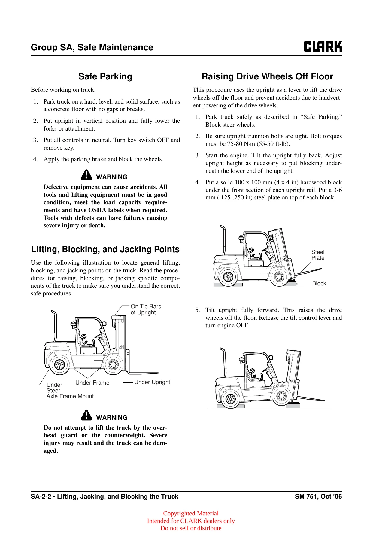
- Group SA – Safe Maintenance: Safety, Lifting, Jacking and Blocking the Truck, Towing
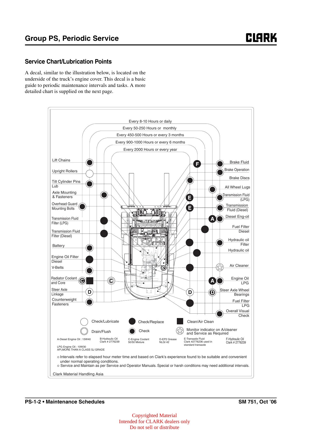
- Group PS – Periodic Service: Maintenance Schedules, The Planned Maintenance Program
- Group 00 – Engine: IVECO NEF Engine (General Specifications, Fuel, Duty-Industrial Application, Overhaul and Technical Specifications, Tools, Engine Replacement), GM V6 4.3L Engine (Removal and Replacement, Repair Procedures, Cooling System)
- Group 01 – Engine Cooling System: Specifications and Description, Troubleshooting, Testing and Maintenance, Radiator Removal and Replacement
- Group 02 – Fuel System: MI-07 LP System (Regulatory Compliance, LPG System Overview, Specifications, Recommended Maintenance, Installation Procedures, Tests and Adjustments, Basic Troubleshooting, Advanced Diagnostics, Parts Description)
- Group 03 – Air Induction and Exhaust System: Specifications and Description, Troubleshooting, Air Induction System Service, Exhaust Systems
- Group 06 – Transaxle: 3WG-116 Transmission (Layout, Disassembly, Reassembly, AEB Setting and Inching Calibration, Troubleshooting), T12313 Transmission (Disassembly, Clutch Service, Regulator Valve, Cleaning and Inspection, Troubleshooting, Transmission Controller)
- Group 13 – Electrical System: Cautions for Working on the Electrical System, Specifications and Features, Electrical Circuit Diagram and Parts Arrangement, Instrument Pod
- Group 20 – Drive Axle: Specification and Description, Differential, Assembly and Disassembly, Troubleshooting
- Group 22 – Wheels and Tires: Specifications and Description, Pneumatic Wheels and Tires
- Group 23 – Brake System: Specifications and Description, Service Brake Troubleshooting, Brake and Inching Pedal Adjustments, Brake Bleeding, Brake Master Cylinder Service, Parking Brake Service
- Group 25 – Steering Column and Gear: Specifications and Description, Troubleshooting, Removal and Replacement, Relief Pressure Check and Adjustment, Steering Gear Overhaul
- Group 26 – Steer Axle: Specifications and Description, Wheel Bearing Maintenance and Adjustment, Removal and Replacement, Overhaul, Steer Cylinder Removal and Replacement, Steer Cylinder Overhaul
- Group 29 – Hydraulic Sump, Filters, and Pump: Specifications and Description, Troubleshooting, Removal and Installation
- Group 30 – Hydraulic Control Valve/Lift Circuit: Specifications and Description, Hydraulic Schematic, Troubleshooting, Pressure Checks and Adjustments, Removal and Replacement, Overhaul
- Group 32 – Tilt Cylinders: Specifications and Description, Checks and Adjustments, Removal and Replacement, Overhaul
- Group 34 – Uprights: Specifications and Description, Troubleshooting, Inspection, Roller Clearance Checks and Shim Adjustments, Cylinder Removal/Shimming/Overhaul/Replacement, Chain Inspection/Adjustment/Replacement, Fork and Carriage Removal and Replacement, Upright Removal and Replacement
- Group 38 – Counterweight and Chassis: Specifications and Description, Counterweight Removal and Replacement, Overhead Guard/Operator’s Cell Removal and Replacement, Floorboard/Cowls/Driver Deck, Operator’s Seat Removal and Replacement
- Group 40 – Specifications: Nameplates and Decals, General Specifications, Hydraulic Fitting Tightening Procedure
This Clark C60 C70 C80 C60-75L Service Manual SM-751 is the complete workshop reference for technicians servicing these forklift trucks. It is organized into Clark’s standard service groups, covering everything from daily maintenance schedules to full component overhaul. The manual addresses both the C60-80D diesel models and the C60-75L LPG models, including the IVECO NEF diesel engine and the GM V6 4.3L LPG engine with the MI-07 fuel system. Every major system is documented with specifications, service procedures, adjustment values, and troubleshooting guidance.
Models and Engines Covered
The Clark C60-80D and C60-75L forklift trucks are covered in full. These models span the 6,000 kg to 8,000 kg capacity range at 600 mm load center (13,500 lb to 17,500 lb at 24 in load center). Two engine platforms are documented throughout the manual. The IVECO NEF diesel engine is a four-cylinder, four-stroke, water-cooled direct-injection unit with a displacement of 4,500 cu cm (275 cu in), rated at 74 kW (99 hp) at 2300 rpm and 398 Nm (294 lb-ft) at 1400 rpm. The GM V6 4.3L LPG engine is a six-cylinder, 90-degree V6 with overhead valves, displacing 4,300 cu cm (262 cu in), rated at 68 kW (91 hp) at 2300 rpm and 317 Nm (234 lb-ft) at 2000 rpm. The LPG fuel system uses the Woodward MI-07 control system with dual fuel trim valves and closed-loop oxygen sensor feedback.
Detailed System Coverage
Each service group in this Clark forklift service manual provides the specifications, procedures, and diagnostic information needed to keep these trucks running correctly in demanding industrial environments.
Engine Service: For the IVECO NEF diesel engine, the manual includes general specifications, lubrication system layout, cooling system design, air induction boost diagram, fuel injection feed system with mechanical rotary pump, overhaul procedures for the cylinder head, timing system, and complete engine disassembly and reassembly. For the GM V6 4.3L LPG engine, you get engine removal and replacement, full repair procedures, cylinder head service, valve train component installation, timing chain and sprocket installation, oil pump and oil pan installation, and engine setup and testing. Detailed specifications for both engines include bearing clearances, journal diameters, torque sequences, and wear limits.
Fuel System: The MI-07 LP system section spans regulatory compliance, system overview, specifications, recommended maintenance, installation procedures, tests and adjustments, basic troubleshooting, advanced diagnostics, and parts description. This includes the N-2007 pressure regulator, CA100 mixer, fuel trim valves, electronic throttle system, heated exhaust gas oxygen sensors, and catalytic muffler. The fuel system operation is explained in detail, from the electric fuel lock-off through the regulator and mixer to the closed-loop air-fuel ratio control.
Transmission Service: The ZF 3WG-116 and Dana T12313 transmissions are covered with complete disassembly and reassembly procedures, clutch service, regulator valve service, AEB setting of the T/M controller, inching calibration, and comprehensive troubleshooting with fault code tables. The transmission controller section explains the APC73-12 system with its self-test functions, fault diagnostics, and installation guidelines. Specific attention is given to clutch pack clearances, bearing preloads, and the AEB (Automatic Electronic Balancing) procedure for clutch calibration.
Hydraulic Systems: Group 29 handles the hydraulic sump, filters, and main pump with removal and installation procedures. Group 30 covers the hydraulic control valve and lift circuit, including full hydraulic schematics, pressure checks and adjustments, removal and replacement, and overhaul. Group 32 focuses on tilt cylinders with drift checks, racking adjustments, and complete overhaul. Group 34 provides extensive upright service information including roller clearance checks, shim adjustments, cylinder removal and overhaul, chain inspection and replacement, and fork and carriage service.
Brake and Steering Systems: Groups 23, 25, and 26 document the brake system, steering column and gear, and steer axle. The brake section covers service brake troubleshooting, brake and inching pedal linkage adjustments, brake bleeding procedures, brake master cylinder service, and parking brake service. Steering column and gear coverage includes the steering gear overhaul, relief pressure checks, and troubleshooting. The steer axle section covers wheel bearing maintenance and adjustment, axle removal and replacement, steering knuckle service, and steer cylinder overhaul.
Electrical System: Group 13 includes circuit diagrams for both C60-80D and C60-75L models, main wire harness layouts, T/M wire harness diagrams, battery mounting, and instrument pod operation. The instrument pod section explains the diagnostic menu system, error code display, password functions, and AEB mode operations. Instrument pod error codes are cross-referenced with the transmission controller fault codes for efficient diagnosis.
Drive Axle and Chassis: Group 20 covers the drive axle with differential service, assembly and disassembly procedures, and troubleshooting. Group 38 covers the counterweight, overhead guard, operator’s cell, floorboard, and seat. Group 22 covers wheels and tires including pneumatic tire maintenance, wheel dismounting and remounting, and tire pressure specifications.
What This Manual Enables You to Do
With the Clark C60 C70 C80 C60-75L Service Manual SM-751, you can confidently perform scheduled maintenance, diagnose faults, remove and reinstall major components, and complete full overhauls of every system on these forklifts. The manual provides the exact torque specifications, clearance values, adjustment procedures, and diagnostic fault codes used by Clark service technicians. Rather than guessing at repair procedures or relying on generic references, you have the complete factory documentation at your fingertips.
For fleet operations, the periodic service schedules and planned maintenance program help establish consistent service intervals. For repair shops, the detailed overhaul procedures for engines, transmissions, hydraulics, and uprights provide the step-by-step guidance needed to rebuild components to factory specifications. For owner-operators, the troubleshooting sections and diagnostic fault code tables help identify problems quickly and determine whether a repair can be handled in-house or requires specialized service.
Get Instant Access to the Complete Clark C60-80D and C60-75L Service Manual
Whether you are a professional forklift technician, a fleet maintenance manager, or an owner-operator who services your own equipment, this Clark C60 C70 C80 C60-75L Service Manual SM-751 gives you the complete factory documentation in one convenient PDF. Stop guessing at torque values, adjustment clearances, or diagnostic procedures. The manual provides the exact specifications and step-by-step procedures Clark used to build and service these trucks.
The PDF format means you can access the manual instantly after purchase. No shipping, no waiting. Use it on any device, whether laptop, tablet, or smartphone. Print the pages you need for the shop and keep the digital copy for quick reference. With approximately 802 pages covering every system in these forklifts, this is the most comprehensive service reference available for the Clark C60-80D and C60-75L models. The manual covers diesel and LPG variants, both transmission options, and every major component from the engine through the upright. Get your copy today and have the complete service documentation ready whenever you need it.
IMAGES PREVIEW
Reviews
There are no reviews yet.