Description
Overview: Canadair Regional Jet Structural Repair Manual – Chapter 53 Fuselage
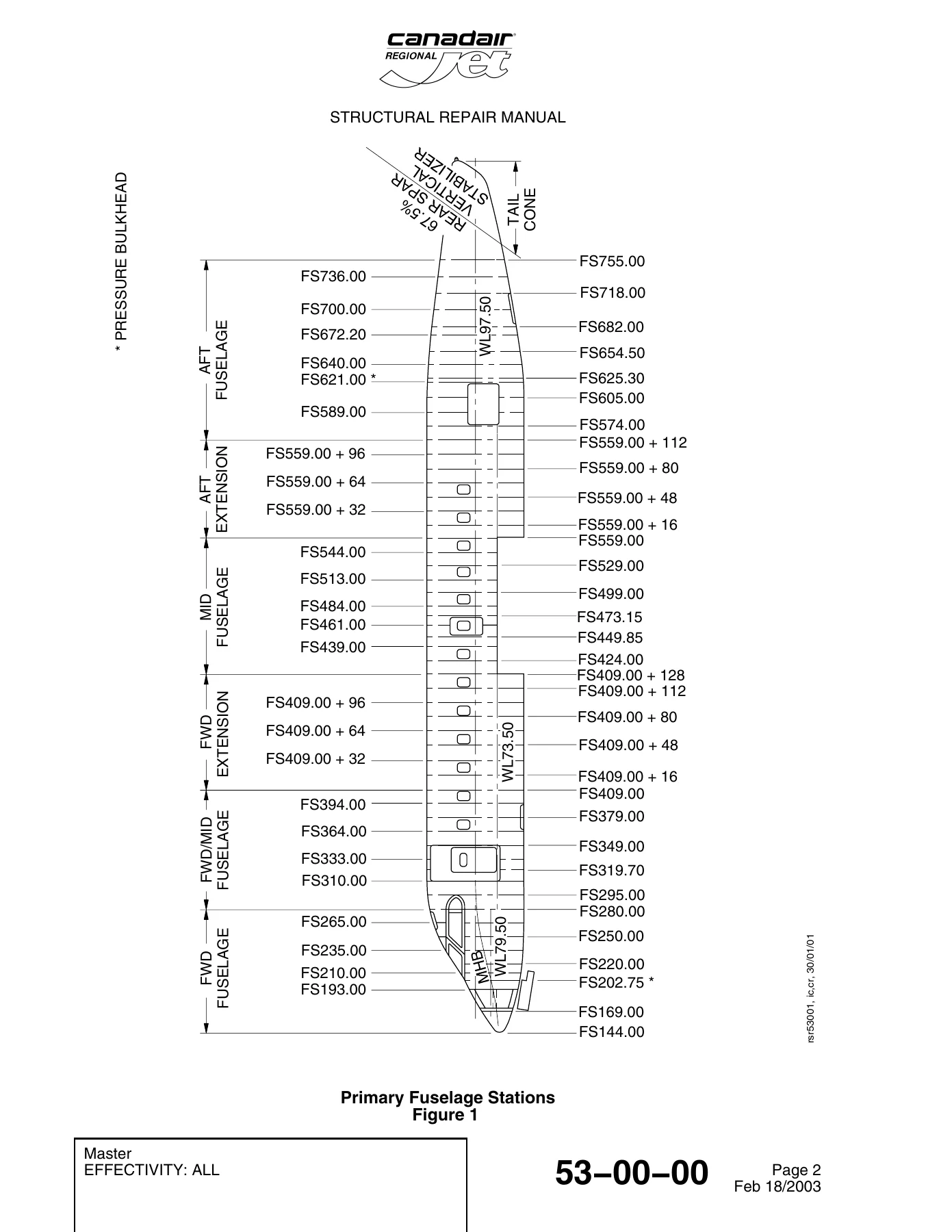
The Canadair Regional Jet Structural Repair Manual – Chapter 53 Fuselage is the definitive engineering and maintenance resource dedicated exclusively to the fuselage structure of the Canadair Regional Jet. Covering airframes from fuselage station FS 144.00 aft to FS 755.00 and beyond to the tail cone and vertical stabilizer rear spar datum, this comprehensive technical document delivers manufacturer-approved data for structural identification, allowable damage assessment, and permanent and temporary repair dispositions. Whether evaluating minor surface scratches in pressurized skin panels, planning a stringer splice repair, restoring frame outer flanges, or repairing critical floor support structures, this factory publication provides the structural classifications, fastener codes, edge distance criteria, and non-destructive testing requirements needed to return aircraft to airworthy condition in full compliance with continuous airworthiness guidelines.
File Details
- Manual Type: Structural Repair Manual (SRM)
- Document Title: Canadair Regional Jet Structural Repair Manual – Chapter 53 Fuselage
- Manufacturer / Brand: Canadair / Bombardier Aerospace
- Applicable Aircraft: Canadair Regional Jet (including CRJ100 and CRJ200 series; effectivity across aircraft serial numbers 7003 through 8400 and subsequent blocks as detailed)
- ATA Chapter: Chapter 53 (Fuselage)
- Effective Publication & Revision Dates: Revision through March 10, 2006 (incorporating baseline standards from February 18, 2003, June 2004, and April/August 2005)
- Total Page Count: 1366 pages
- Language: English
- File Format: Digital PDF (Text-selectable, high-resolution technical diagrams, printable)
Chapters & Sections Covered
- 53-00-00 Fuselage – General: Structural classification (primary and secondary structure definitions), primary fuselage stations layout (FS 144.00 through FS 755.00), ATA section mapping (53-10 through 53-80), and overall fuselage structural identification.
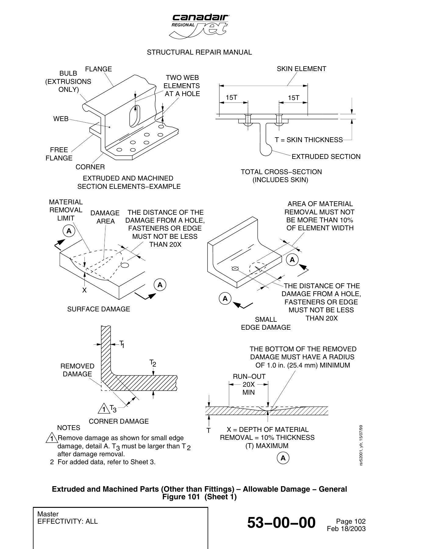
- 53-00-00 Fuselage Internal Structure – Allowable Damage: General damage assessment guidelines, blend-out calculations, run-out ratios (20X minimum), corner/edge radius requirements (1.0 in / 25.4 mm minimum), and 10% cross-sectional area loss limits for extruded, machined, and formed sheet metal components.
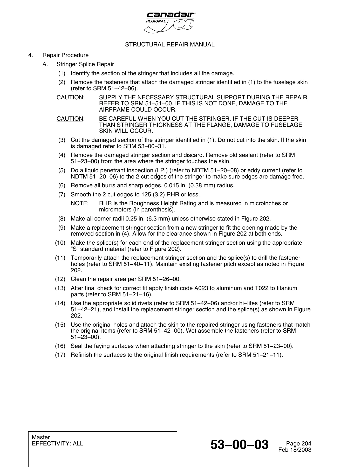
- 53-00-03 Stringers: Structural identification of fuselage stringers, damage reporting protocols, and complete splice repair instructions for extruded stringer geometries (including S6142, S6451, S6763, S6764, S6781, S6784, S6785, S6788, S6807, S6810, S6812, S6881, and S6899) utilizing formed splice sections S6957, S6958, and S6959.
- 53-00-15 Frames: Allowable damage limits, Repair No. 1 Frame Splice Repairs over T-stringers and Z-stringers (applicable FS 295.00 to FS 654.50, up to 0.063 in thickness), and Repair No. 2 Frame Outer Flange Repairs with repair angles and fillers.
- 53-00-27 Fuselage Fittings: Structural damage evaluation criteria and manufacturer coordination instructions for primary fuselage fittings.
- 53-00-31 Skin and Plating – Structural Identification & Allowable Damage: General skin identification, flight operation limits (flight cycles vs damage depth and length graphs), localized damage depth limits across fuselage stations FS 169.00 to FS 755.00, chem-milled pocket rules, dent depth-to-width ratios (W/D >= 25), and rivet hole plugging standards.
- 53-00-31 Skin and Plating Repairs (General & Approved Repairs 1 through 7): Proximity limitations between adjacent cutouts in pressurized and non-pressurized zones, structural deviation inspection requirements (SDIR), Repair No. 1 External Non-Flush Permanent Repairs (Pressurized Area), Repair No. 2 External Non-Flush Temporary Repairs (4,000 flight cycles limit), Repair No. 3 External Non-Flush Permanent Repairs (Non-Pressurized Area), Repair No. 4 External Non-Flush Temporary Repairs (Non-Pressurized Area), Repair No. 5 External Flush Permanent Repairs using buttstraps and skin inserts, Repair No. 6 Fuselage Skin Splice Repairs (two bays and over single frames), and Repair No. 7 Generic Non-Flush Skin Repair around Passenger Cabin Window Cut-Outs (REO 601R-53-00-026).
- 53-00-43 Floor Support Structure Repairs: Repair No. 1 Floorbeam Flange Repairs for aluminum (clad 7075-T62/2024-T3) and titanium (MIL-T-9046 CP-1 / Ti-6Al-4V) floorbeams between frames and over frames; Repair No. 2 Floor Beam Splice Repairs with channel splices, laminated shims, and blind nuts.
- 53-00-47 Passenger & Cargo Compartment Floor Panels: Structural identification of Grade I, Grade II, and Grade III Ciba-Geigy Fibrelam 2000 aramid/phenolic Nomex honeycomb panels with unidirectional glass and graphite/epoxy skins, damage limits for soft spots/delaminations/scratches, and repair cross-references to Hexcel Composites CMM (CGFP-02) and generic repair engineering orders (SGREO).
- 53-00-49 Passenger Seat & Cargo Tie-Down Tracks: Structural identification of 7075-T6 floor rails, side seat rail assemblies, allowable wear, and damage inspection guidelines across passenger and cargo compartments.
- 53-10-00 & 53-11-00 Fuselage FS 144.00 to FS 280.00 Main Structure: Forward airframe architecture breakdown including primary structural layout and component cross-indexing.
- 53-11-03 Stringers (FS 169.00 to FS 280.00): Comprehensive mapping of left and right stringers (STR 0 through STR 27), material callouts (2024-T62 extrusions and 2024-T42 formed sheet), and approved repair routing.
- 53-11-15 Frames (FS 144.00 to FS 280.00): Detailed structural identification and part breakdowns for the FS 169.00 Sheet Metal Bulkhead, FS 169.00 Machined Bulkhead (7475-T7351 plate), and intermediate frames at FS 193.00, FS 210.00, FS 220.00, FS 235.00, FS 241.60, FS 248.10, FS 250.00, FS 254.68, FS 265.00, FS 267.00, and FS 276.00.
- 53-11-17 Intercostals (FS 144.00 to FS 280.00): Part schedules, bracket configurations, material callouts (clad 2024-T42, clad 7075-T62), and allowable damage limits.
- 53-11-19 Bulkheads (FS 144.00 to FS 280.00): Engineering layouts for the FS 202.75 Forward Pressure Bulkhead (including titanium capping angle 601R34030, web doublers, tension clips) and the FS 280.00 Pilot’s Bulkhead, complete with web/doubler damage thresholds and approved REO listing.
- 53-11-23 Surround Structures (FS 144.00 to FS 280.00): Structural identification and framing assemblies for the Crew Escape Hatch, Air-Driven Generator (ADG) door surround, and Electronics Bay access doors.
- 53-11-31 Skin and Plating (FS 169.00 to FS 280.00): Skin panel gages (t1 through t5 from 0.030 in to 0.063 in), chem-milled pocket boundaries, buttstraps, splice straps, doubler plates, and allowable rework limits.
- 53-11-35 Windshield & Side-Window Frame Structure: Structural identification of machined 7050-T7451 center posts, forward upper/lower sills, side posts, and aft sills; explicit allowable damage and chamfering limits (45-degree chamfer, 10% max thickness reduction) for the windshield and side-window lower sills.
- 53-11-43 Floor Support Structure (FS 169.00 to FS 280.00): Flight compartment and forward equipment compartment floor grids, floor beam web/flange dent criteria, and fastener hole edge distance allowances.
- 53-11-47 Floor Panels (FS 169.00 to FS 280.00): Flight deck aluminum alloy floor panels (clad 7075-T6) and walkway composite panels.
- 53-11-49 Flight-Compartment Seat Tracks: Fixed and removable seat track structural identification, seat metering pin hole wear limits (0.290 in max forward/aft elongation), track surface blending limits, and sleeve-spacer callouts.
- 53-11-67 Nose-Landing-Gear Support Structure: Structural identification of the NLG beam assembly (FS 202.75 to FS 235.00), sidewalls, upper panel well assembly, door hinge fittings, and uplock structure; specific allowable damage tables for webs, channel stiffeners, and 2D fastener clearance zones.
- 53-12-55 Underfloor Crawlway & Support Structure: Structural identification and allowable damage for underfloor crawlway assemblies and graphite-faced nylon-honeycomb panels (P/N 601R31669).
- Full Fuselage Coverage Summary: Cross-indexing chapters spanning mid fuselage, forward and aft fuselage plugs/extensions, center fuselage pressure box (53-41-46), baggage door and service door surrounds, wing fairings, APU compartment (53-62-57), radome (53-81-00), and tail cone (53-84-00).
Together, these sections equip structural technicians, airframe mechanics, and licensed aeronautical engineers with the exact structural specifications, engineering illustrations, part numbers, and fastener installation procedures required to maintain airframe structural integrity under strict FAA and Transport Canada airworthiness regulations.
Engineering Procedures & Damage Tolerance Guidelines
The Canadair Regional Jet Structural Repair Manual – Chapter 53 Fuselage emphasizes damage tolerance analysis, aerodynamic smoothness criteria, and continuous airworthiness record-keeping. Whenever structural damage is identified on the Canadair Regional Jet fuselage, technicians must first cross-reference general versus specific allowable damage criteria. Key engineering principles detailed in this manual include:
Complete PDF Bookmark Tree
Complete Bookmarks
The complete bookmarks in the “Canadair Regional Jet Structural Repair Manual – Chapter 53 Fuselage” are as follows:
+Chapter 53p. 1
Effective Pagesp. 1
Contentsp. 19
+Section 00p. 59
+53-00-00p. 59
+53-00-00-00p. 59
+Primary Fuselage Stationsp. 60
+Fuselage ATA Sectionsp. 61
+Fuselage Structural Identificationp. 62
+53-00-00-01p. 63
+Extruded and Machined Parts (Other than Fittings) – Allowable Damage – Generalp. 64
Figure 101 (Sheet 1)p. 64
Figure 101 (Sheet 2)p. 65
+Formed Parts – Allowable Damage – Generalp. 67
Figure 102 (Sheet 1)p. 67
+53-00-03p. 69
+53-00-03-00p. 69
+Stringers – Structural Identificationp. 70
53-00-03-01p. 71
+53-00-03-02p. 73
+Stringer – Splice Repairp. 77
Figure 202 (Sheet 1)p. 77
Figure 202 (Sheet 2)p. 78
Figure 202 (Sheet 3)p. 79
Figure 202 (Sheet 4)p. 80
Figure 202 (Sheet 5)p. 81
Figure 202 (Sheet 6)p. 82
+53-00-15p. 83
53-00-15-01p. 83
+53-00-15-02-01p. 85
+Repair No. 1 – Fuselage Frame – Splice Repairp. 87
Figure 201 (Sheet 1)p. 87
Figure 201 (Sheet 2)p. 88
Figure 201 (Sheet 3)p. 89
Figure 201 (Sheet 4)p. 90
+53-00-15-02-02p. 91
+Repair No. 2 – Fuselage Frame Outer Flange Repairp. 94
Figure 202 (Sheet 1)p. 94
Figure 202 (Sheet 2)p. 95
Figure 202 (Sheet 3)p. 96
+53-00-27p. 97
53-00-27-01p. 97
53-00-27-02p. 99
+53-00-31p. 101
+53-00-31-00p. 101
+Skin and Plating – Structural Identificationp. 102
+53-00-31-01p. 103
+Fuselage Skin and Plating – Flight Operation Limitsp. 104
+Fuselage Skin and Plating – Local Damage Depth Limitsp. 105
Figure 102 (Sheet 1)p. 105
Figure 102 (Sheet 2)p. 106
Figure 102 (Sheet 3)p. 107
Figure 102 (Sheet 4)p. 108
+Fuselage Skin and Plating – Allowable Damage – Generalp. 109
Figure 103 (Sheet 1)p. 109
Figure 103 (Sheet 2)p. 110
+53-00-31-02p. 113
+Proximity Limitation for Non-Flush Skin Repair Pressurized Areap. 115
+Proximity Limitations for Non-Flush Skin Repair in Pressurized Areap. 116
+Proximity Limitations for Non-Flush Skin Repair in Pressurized Areap. 117
+Proximity Limitations for Flush Skin Repair in Pressurized Areap. 118
+Proximity Limitations for Flush Skin Repair in Pressurized Areap. 119
+Proximity Limitations for Flush Skin Repair in Pressurized Areap. 120
+Proximity Limitations for Flush Skin Repair in Pressurized Areap. 121
+Proximity Limitations for Flush Skin Repair in Pressurized Areap. 122
+Inspection Requirementsp. 123
Figure 209 (Sheet 1)p. 123
Figure 209 (Sheet 2)p. 124
Figure 209 (Sheet 3)p. 125
Figure 209 (Sheet 4)p. 126
+53-00-31-02-01p. 127
+Repair No. 1 – Fuselage Skin Repair Over Single Bay Areap. 131
+Repair No. 1 – Fuselage Skin Repair Continuous Over Framesp. 132
+Repair No. 1 – Fuselage Skin Repair Continuous Over Stringersp. 133
+Repair No. 1 – Fuselage Skin Repair Doubler Terminating Between Framesp. 134
Figure 204 (Sheet 1)p. 134
Figure 204 (Sheet 2)p. 135
Figure 204 (Sheet 3)p. 136
+Repair No. 1 – Details of Cut Line Over Framesp. 137
+Repair No. 1 – Details of Cut Line Over Stringersp. 138
+53-00-31-02-02p. 139
+Repair No. 2 – Fuselage Skin Temporary Repair Doublers Continuous Over Frame and Ending at Longitudinal Skin Panel Jointp. 141
+Repair No. 2 – Fuselage Skin Temporary Repair Continuous Over Framesp. 142
+Repair No. 2 – Fuselage Skin Temporary Repair Doubler Continuous Over Stringersp. 143
+Repair No. 2 – Fuselage Skin Temporary Repair Doubler Terminating Between Framesp. 144
Figure 204 (Sheet 1)p. 144
Figure 204 (Sheet 2)p. 145
+Repair No. 2 – Temporary Repair – Details of Cut Line Over Framesp. 146
+Repair No. 2 – Temporary Repair – Details of Cut Line Over Stringersp. 147
+53-00-31-02-03p. 149
+Repair No. 3 – Non-Flush Permanent Repair Over Single Bay Areap. 151
+Repair No. 3 – Non-Flush Permanent Repair Continuous Over Framesp. 152
+Repair No. 3 – Non-Flush Permanent Repair Continuous Over Stringersp. 153
Figure 203 (Sheet 1)p. 153
Figure 203 (Sheet 2)p. 154
+Repair No. 3 – Non-Flush Permanent Repair – Doubler Terminating Between Framesp. 155
Figure 204 (Sheet 1)p. 155
Figure 204 (Sheet 2)p. 156
Figure 204 (Sheet 3)p. 157
+Repair No. 3 – Non-Flush Permanent Repair – Details of Cut Line Over Stringers and Framesp. 158
+53-00-31-02-04p. 159
+Repair No. 4 – Temporary Non-Flush Repair Over Single Bay Areap. 161
+Repair No. 4 – Temporary Non-Flush Repair Continuous Over Framesp. 162
+Repair No. 4 – Temporary Non-Flush Repair Continuous Over Stringersp. 163
Figure 203 (Sheet 1)p. 163
Figure 203 (Sheet 2)p. 164
+Repair No. 4 – Temporary Non-Flush Repair Doubler Terminating Between Framesp. 165
Figure 204 (Sheet 1)p. 165
Figure 204 (Sheet 2)p. 166
Figure 204 (Sheet 3)p. 167
+Repair No. 4 – Temporary Non-Flush Repair – Details of Cut Line Over Stringer and Framesp. 168
+53-00-31-02-05p. 169
+Repair No. 5 – Permanent Flush Repair Between Frames and Over One Stringerp. 172
Figure 201 (Sheet 1)p. 172
Figure 201 (Sheet 2)p. 173
+Repair No. 5 – Permanent Flush Repair Between Frames and Over Stringers (Max. 4 Bays)p. 174
Figure 202 (Sheet 1)p. 174
Figure 202 (Sheet 2)p. 175
+Repair No. 5 – Permanent Flush Repair Continuous Over One Frame and One Stringerp. 176
Figure 203 (Sheet 1)p. 176
Figure 203 (Sheet 2)p. 177
+Repair No. 5 – Permanent Flush Repair Continuous Over One Frame and Two Stringersp. 178
Figure 204 (Sheet 1)p. 178
Figure 204 (Sheet 2)p. 179
+Repair No. 5 – Permanent Flush Repairs – Detail of Bend Relief and Detail of Buttstrap Installation over Frame With More Than 5 Rivet Pitchesp. 180
+53-00-31-02-06p. 181
+Repair No. 6 – Fuselage Skin Splice Two Bays Repairp. 184
Figure 201 (Sheet 1)p. 184
Figure 201 (Sheet 2)p. 185
Figure 201 (Sheet 3)p. 186
+Repair No. 6 – Fuselage Skin Splice Repair Over One Framep. 187
Figure 202 (Sheet 1)p. 187
Figure 202 (Sheet 2)p. 188
Figure 202 (Sheet 3)p. 189
Figure 202 (Sheet 4)p. 190
+53-00-31-02-07p. 191
+Fuselage Skin and Plating – Repairsp. 194
Figure 202 (Sheet 1)p. 194
Figure 202 (Sheet 2)p. 195
Figure 202 (Sheet 3)p. 196
Figure 202 (Sheet 4)p. 197
Figure 202 (Sheet 5)p. 198
Figure 202 (Sheet 6)p. 199
Figure 202 (Sheet 7)p. 200
Figure 202 (Sheet 8)p. 201
Figure 202 (Sheet 9)p. 202
Figure 202 (Sheet 10)p. 203
+53-00-43p. 205
+53-00-43-02-01p. 205
+Aluminum Floorbeam Flange Repairp. 209
Figure 203 (Sheet 1)p. 209
Figure 203 (Sheet 2)p. 210
Figure 203 (Sheet 3)p. 211
Figure 203 (Sheet 4)p. 212
+Titanium Floorbeam Flange Repairp. 213
Figure 204 (Sheet 1)p. 213
Figure 204 (Sheet 2)p. 214
Figure 204 (Sheet 3)p. 215
Figure 204 (Sheet 4)p. 216
+53-00-43-02-02p. 217
+Aluminum Floor Beam – Splice Repairp. 221
Figure 203 (Sheet 1)p. 221
Figure 203 (Sheet 2)p. 222
Figure 203 (Sheet 3)p. 223
Figure 203 (Sheet 4)p. 224
+Titanium Floor Beam – Splice Repairp. 225
Figure 204 (Sheet 1)p. 225
Figure 204 (Sheet 2)p. 226
Figure 204 (Sheet 3)p. 227
Figure 204 (Sheet 4)p. 228
+53-00-47p. 229
+53-00-47-00p. 229
+Passenger and Cargo Compartment Floor Panels – Structural Identificationp. 230
Figure 1 (Sheet 1)p. 230
Figure 1 (Sheet 2)p. 231
53-00-47-01p. 233
53-00-47-02p. 235
+53-00-49p. 237
+53-00-49-00p. 237
+Floor Rails – Passenger Seat and Cargo Tie-Down Tracks – Structural Identificationp. 238
+Side Seat Rails – Passenger Seat Tracks – Structural Identificationp. 240
53-00-49-01p. 243
53-00-49-02p. 245
+Section 10p. 247
+53-10-00p. 247
+Fuselage FS144.00 to FS280.00 – Structural Identificationp. 248
Figure 1 (Sheet 1)p. 248
Figure 1 (Sheet 2)p. 249
+Section 11p. 251
+53-11-00p. 251
+Fuselage FS144.00 to FS280.00 – Structural Identificationp. 252
Figure 1 (Sheet 1)p. 252
Figure 1 (Sheet 2)p. 253
+53-11-03p. 255
+53-11-03-00p. 255
+Stringers, FS169.00 to FS280.00 – Structural Identificationp. 256
Figure 1 (Sheet 1)p. 256
Figure 1 (Sheet 2)p. 257
53-11-03-01p. 259
53-11-03-02p. 261
+53-11-15p. 263
+53-11-15-00p. 263
+Frame (Sheet Metal Bulkhead), FS169.00 – Structural Identificationp. 264
+Frame (Machined Bulkhead), FS169.00 – Structural Identificationp. 267
Figure 2 (Sheet 1)p. 267
Figure 2 (Sheet 2)p. 268
Figure 2 (Sheet 3)p. 269
+Frames, FS193.00 to FS265.00 – Structural Identificationp. 274
Figure 3 (Sheet 1)p. 274
Figure 3 (Sheet 2)p. 275
+Frames, FS241.60 to FS276.00 – Structural Identificationp. 281
Figure 4 (Sheet 1)p. 281
Figure 4 (Sheet 2)p. 282
Figure 4 (Sheet 3)p. 283
Figure 4 (Sheet 4)p. 284
53-11-15-01p. 287
53-11-15-02p. 289
+53-11-17p. 291
+53-11-17-00p. 291
+Intercostals, FS144.00 to FS280.00 – Structural Identificationp. 292
Figure 1 (Sheet 1)p. 292
Figure 1 (Sheet 2)p. 293
53-11-17-01p. 297
53-11-17-02p. 299
+53-11-19p. 301
+53-11-19-00p. 301
+Pressure Bulkhead, FS202.75 – Structural Identificationp. 302
Figure 1 (Sheet 1)p. 302
Figure 1 (Sheet 2)p. 303
+Pilot's Bulkhead, FS280.00 – Structural Identificationp. 308
53-11-19-01p. 313
53-11-19-02p. 315
+53-11-23p. 317
+53-11-23-00p. 317
+Surround Structure, Crew Escape Hatch – Structural Identificationp. 318
Figure 1 (Sheet 1)p. 318
Figure 1 (Sheet 2)p. 319
Figure 1 (Sheet 3)p. 320
Figure 1 (Sheet 4)p. 321
+Surround Structure, ADG – Structural Identificationp. 324
+Surround Structure, Electronics Bay Access Doors – Structural Identificationp. 327
53-11-23-01p. 331
53-11-23-02p. 333
+53-11-31p. 335
+53-11-31-00p. 335
+Skin and Plating, FS169.00 to FS280.00 – Structural Identificationp. 336
Figure 1 (Sheet 1)p. 336
Figure 1 (Sheet 2)p. 337
Figure 1 (Sheet 3)p. 338
Figure 1 (Sheet 4)p. 339
53-11-31-01p. 343
53-11-31-02p. 345
+53-11-35p. 347
+53-11-35-00p. 347
+Windshield and Side-Window Frame Structure – Structural Identificationp. 348
Figure 1 (Sheet 1)p. 348
Figure 1 (Sheet 2)p. 349
Figure 1 (Sheet 3)p. 350
+53-11-35-01p. 353
+Windshield and Side Window Lower Sill – Allowable Damagep. 354
53-11-35-02p. 355
+53-11-43p. 357
+53-11-43-00p. 357
+Floor Support Structure FS169.00 to FS280.00 – Structural Identificationp. 358
+53-11-43-01p. 361
+Floor Support Structure, FS169.00 to FS280.00 – Allowable Damagep. 362
Figure 101 (Sheet 1)p. 362
Figure 101 (Sheet 2)p. 363
Figure 101 (Sheet 3)p. 364
Figure 101 (Sheet 4)p. 365
53-11-43-02p. 369
+53-11-47p. 371
+53-11-47-00p. 371
+Floor Panels, FS169.00 to FS280.00 – Structural Identificationp. 372
Figure 1p. 372
+Chapter 53p. 375
53-11-47-01p. 375
53-11-47-02p. 377
+53-11-49p. 379
+53-11-49-00p. 379
+Flight-Compartment Seat Tracks – Structural Identificationp. 380
+53-11-49-01p. 383
+Flight Compartment Seat Tracks – Allowable Damagep. 384
Figure 101 (Sheet 1)p. 384
Figure 101 (Sheet 2)p. 385
53-11-49-02p. 387
+53-11-67p. 389
+53-11-67-00p. 389
+Nose-Landing-Gear Support Structure – Structural Identificationp. 390
Figure 1 (Sheet 1)p. 390
Figure 1 (Sheet 2)p. 391
Figure 1 (Sheet 3)p. 392
Figure 1 (Sheet 4)p. 393
Figure 1 (Sheet 5)p. 394
Figure 1 (Sheet 6)p. 395
Figure 1 (Sheet 7)p. 396
Figure 1 (Sheet 8)p. 397
+53-11-67-01p. 407
+Nose-Landing-Gear Support Structure – Allowable Damagep. 408
Figure 101 (Sheet 1)p. 408
Figure 101 (Sheet 2)p. 409
Figure 101 (Sheet 3)p. 410
53-11-67-02p. 413
+Section 12p. 415
+53-12-55p. 415
+53-12-55-00p. 415
+Underfloor Crawlway and Support Structure, FS144.00 to FS280.00 – Structural Identificationp. 416
+53-12-55-01p. 419
+Underfloor Crawlway and Support Structure FS144.00 to FS280.00 – Allowable Damagep. 420
Figure 101 (Sheet 1)p. 420
53-12-55-02p. 423
+Section 20p. 425
+Section 21p. 427
+53-21-00p. 427
+Fuselage FS280.00 to FS409.00 – Structural Identificationp. 428
Figure 1 (Sheet 1)p. 428
Figure 1 (Sheet 2)p. 429
+53-21-03p. 431
+53-21-03-00p. 431
+Stringers, FS280.00 to FS409.00 – Structural Identificationp. 432
Figure 1 (Sheet 1)p. 432
Figure 1 (Sheet 2)p. 433
53-21-03-01p. 439
53-21-03-02p. 441
+53-21-15p. 443
+53-21-15-00p. 443
+Frame FS295.00 – Structural Identificationp. 444
+Frame FS310.00 – Structural Identificationp. 447
+Frame FS319.70 – Structural Identificationp. 451
+Frame FS333.00 – Structural Identificationp. 454
+Frame FS349.00 – Structural Identificationp. 457
+Frame FS364.00 – Structural Identificationp. 461
+Frame FS379.00 – Structural Identificationp. 464
+Frame FS394.00 – Structural Identificationp. 467
+Frame FS409.00 – Structural Identificationp. 470
53-21-15-01p. 473
53-21-15-02p. 475
+53-21-17p. 477
+53-21-17-00p. 477
+Intercostals, FS280.00 to FS490.00 – Structural Identificationp. 478
Figure 1 (Sheet 1)p. 478
Figure 1 (Sheet 2)p. 479
Figure 1 (Sheet 3)p. 480
Figure 1 (Sheet 4)p. 481
Figure 1 (Sheet 5)p. 482
Figure 1 (Sheet 6)p. 483
Figure 1 (Sheet 7)p. 484
Figure 1 (Sheet 8)p. 485
Figure 1 (Sheet 9)p. 486
Figure 1 (Sheet 10)p. 487
Figure 1 (Sheet 11)p. 488
Figure 1 (Sheet 12)p. 489
Figure 1 (Sheet 13)p. 490
Figure 1 (Sheet 14)p. 491
Figure 1 (Sheet 15)p. 492
Figure 1 (Sheet 16)p. 493
Figure 1 (Sheet 17)p. 494
53-21-17-01p. 503
53-21-17-02p. 505
+53-21-23p. 507
+53-21-23-00p. 507
+Doors – Identification and Locationp. 508
+Passenger Door Surround-Structure – Structural Identificationp. 509
Figure 2 (Sheet 1)p. 509
Figure 2 (Sheet 2)p. 510
Figure 2 (Sheet 3)p. 511
Figure 2 (Sheet 4)p. 512
+Service Door Surround-Structure – Structural Identificationp. 517
Figure 3 (Sheet 1)p. 517
Figure 3 (Sheet 2)p. 518
Figure 3 (Sheet 3)p. 519
Figure 3 (Sheet 4)p. 520
Figure 3 (Sheet 5)p. 521
Figure 3 (Sheet 6)p. 522
Figure 3 (Sheet 7)p. 523
Figure 3 (Sheet 8)p. 524
Figure 3 (Sheet 9)p. 525
+Avionics Door Surround-Structure – Structural Identificationp. 529
Figure 4 (Sheet 1)p. 529
Figure 4 (Sheet 2)p. 530
Figure 4 (Sheet 3)p. 531
+Potable Water System Service Door Surround-Structure- Structural Identificationp. 533
53-21-23-01p. 535
53-21-23-02p. 537
+53-21-27p. 539
+53-21-27-00p. 539
+Passenger Door Surround-Fittings – Structural Identificationp. 540
+Service Door Surround-Fittings – Structural Identificationp. 543
Figure 2 (Sheet 1)p. 543
Figure 2 (Sheet 2)p. 544
Figure 2 (Sheet 3)p. 545
Figure 2 (Sheet 4)p. 546
Figure 2 (Sheet 5)p. 547
+Avionics Door Surround-Fittings – Structural Identificationp. 550
53-21-27-01p. 553
53-21-27-02p. 555
+53-21-31p. 557
+53-21-31-00p. 557
+Skin and Plating, FS280.00 to FS409.00 – Structural Identificationp. 558
53-21-31-01p. 563
53-21-31-02p. 565
+53-21-31-02-01p. 567
+Repair One – Repair to Fuselage Skin Around Passenger Door Cut-Outp. 570
Figure 202 (Sheet 1)p. 570
Figure 202 (Sheet 2)p. 571
Figure 202 (Sheet 3)p. 572
Figure 202 (Sheet 4)p. 573
Figure 202 (Sheet 5)p. 574
Figure 202 (Sheet 6)p. 575
+53-21-31-02-02p. 577
+Repair Two – Repair to Fuselage Skin Around Service Door Cut-Outp. 580
Figure 202 (Sheet 1)p. 580
Figure 202 (Sheet 2)p. 581
Figure 202 (Sheet 3)p. 582
Figure 202 (Sheet 4)p. 583
Figure 202 (Sheet 5)p. 584
Figure 202 (Sheet 6)p. 585
+53-21-43p. 587
+53-21-43-00p. 587
+Floor Support Structure, FS280.00 to FS409.00 – Structural Identificationp. 588
Figure 1 (Sheet 1)p. 588
Figure 1 (Sheet 2)p. 589
53-21-43-01p. 591
53-21-43-02p. 593
53-21-47p. 595
+53-21-49p. 597
+53-21-49-00p. 597
+Seat Tracks, FS280.00 to FS409.00 – Structural Identificationp. 598
Figure 1 (Sheet 1)p. 598
Figure 1 (Sheet 2)p. 599
+53-21-49-01p. 603
+Passenger Seat Tracks, FS280.00 to FS409.00 – Allowable Damagep. 604
53-21-49-02p. 605
+Section 22p. 607
+53-22-55p. 607
+53-22-55-00p. 607
+Underfloor Crawlway and Support Structure, FS280.00 to FS409.00 – Structural Identificationp. 608
53-22-55-01p. 611
53-22-55-02p. 613
+Section 30p. 615
+Section 31p. 617
+53-31-00p. 617
+Fuselage Main Structure, FS409.00 to FS409.00+128 – Structural Identificationp. 618
+53-31-03p. 619
+53-31-03-00p. 619
+Stringers, FS409.00 to FS409.00+128 – Structural Identificationp. 620
Figure 1 (Sheet 1)p. 620
Figure 1 (Sheet 2)p. 621
53-31-03-01p. 625
53-31-03-02p. 627
+53-31-15p. 629
+53-31-15-00p. 629
+Frames, FS409.00 to FS409.00+128 – Structural Identificationp. 630
Figure 1 (Sheet 1)p. 630
Figure 1 (Sheet 2)p. 631
Figure 1 (Sheet 3)p. 632
Figure 1 (Sheet 4)p. 633
Figure 1 (Sheet 5)p. 634
Figure 1 (Sheet 6)p. 635
Figure 1 (Sheet 7)p. 636
53-31-15-01p. 641
53-31-15-02p. 643
+53-31-23p. 645
+53-31-23-00p. 645
+Door Surround Structure, Refuel/Defuel Panel – Structural Identificationp. 646
53-31-23-01p. 649
53-31-23-02p. 651
+53-31-31p. 653
+53-31-31-00p. 653
+Skin and Plating, FS409.00 to FS409.00+128 – Structural Identificationp. 654
Figure 1 (Sheet 1)p. 654
Figure 1 (Sheet 2)p. 655
Figure 1 (Sheet 3)p. 656
Figure 1 (Sheet 4)p. 657
53-31-31-01p. 661
53-31-31-02p. 663
+53-31-33p. 665
+53-31-33-00p. 665
+Forward Keel Longeron Beam – Structural Identificationp. 666
+53-31-33-01p. 671
+Forward Keel Longeron Beam – Allowable Damagep. 672
Figure 101 (Sheet 1)p. 672
53-31-33-02p. 675
+53-31-43p. 677
+53-31-43-00p. 677
+Floor Support Structure FS409.00 to FS409.00+128 – Structural Identificationp. 678
Figure 1 (Sheet 1)p. 678
Figure 1 (Sheet 2)p. 679
Figure 1 (Sheet 3)p. 680
53-31-43-01p. 683
53-31-43-02p. 685
+53-31-45p. 687
+53-31-45-00p. 687
+Pressure Box – Structural Identificationp. 688
53-31-45-01p. 691
53-31-45-02p. 693
53-31-47p. 695
+53-31-49p. 697
+53-31-49-00p. 697
+Seat Tracks, FS409.00 + 228 – Structural Identificationp. 698
Figure 1 (Sheet 1)p. 698
Figure 1 (Sheet 2)p. 699
Figure 1 (Sheet 3)p. 700
53-31-49-01p. 703
53-31-49-02p. 705
+Section 40p. 707
+Section 41p. 709
+53-41-00p. 709
+Fuselage Main Structure, FS409.00+128 to FS559.00 – Structural Identificationp. 710
+53-41-03p. 711
+53-41-03-00p. 711
+Stringers, FS409.00+128 to FS559.00 – Structural Identificationp. 712
53-41-03-01p. 715
53-41-03-02p. 717
+53-41-15p. 719
+53-41-15-00p. 719
+Frames, FS409.00+128 to FS559.00 – Structural Identificationp. 720
Figure 1 (Sheet 1)p. 720
Figure 1 (Sheet 2)p. 721
Figure 1 (Sheet 3)p. 722
Figure 1 (Sheet 4)p. 723
Figure 1 (Sheet 5)p. 724
Figure 1 (Sheet 6)p. 725
Figure 1 (Sheet 7)p. 726
Figure 1 (Sheet 8)p. 727
Figure 1 (Sheet 9)p. 728
Figure 1 (Sheet 10)p. 729
53-41-15-01p. 735
53-41-15-02p. 737
+53-41-17p. 739
+Intercostals FS409.00+128 to FS559.00 – Allowable Damagep. 740
Figure 101 (Sheet 1)p. 740
Figure 101 (Sheet 2)p. 741
Figure 101 (Sheet 3)p. 742
Figure 101 (Sheet 4)p. 743
+53-41-19p. 747
+53-41-19-00p. 747
+Bulkheads, FS409.00+128 to FS559.00 – Structural Identificationp. 748
Figure 1 (Sheet 1)p. 748
Figure 1 (Sheet 2)p. 749
53-41-19-01p. 753
53-41-19-02p. 755
+53-41-23p. 757
+53-41-23-00p. 757
+Surround Structure, Overwing Emergency Exit – Structural Identificationp. 758
Figure 1 (Sheet 1)p. 758
Figure 1 (Sheet 2)p. 759
Figure 1 (Sheet 3)p. 760
53-41-23-01p. 763
53-41-23-02p. 765
+53-41-31p. 767
+53-41-31-00p. 767
+Skin and Plating FS409+128 to FS559.00 – Structural Identificationp. 768
Figure 1 (Sheet 1)p. 768
Figure 1 (Sheet 2)p. 769
Figure 1 (Sheet 3)p. 770
Figure 1 (Sheet 4)p. 771
Figure 1 (Sheet 5)p. 772
Figure 1 (Sheet 6)p. 773
53-41-31-01p. 779
53-41-31-02p. 781
+53-41-33p. 783
+53-41-33-01p. 783
+Underfloor Longeron – Allowable Damagep. 784
Figure 101 (Sheet 1)p. 784
Figure 101 (Sheet 2)p. 785
Figure 101 (Sheet 3)p. 786
53-41-33-02p. 789
+53-41-43p. 791
+53-41-43-00p. 791
+Pressure Floor Support Structure – Structural Identificationp. 792
Figure 1 (Sheet 1)p. 792
Figure 1 (Sheet 2)p. 793
53-41-43-01p. 797
53-41-43-02p. 799
+53-41-45p. 801
+53-41-45-00p. 801
+Pressure Floor Structure FS409.00+128 to FS559.00 – Structural Identificationp. 802
Figure 1 (Sheet 1)p. 802
Figure 1 (Sheet 2)p. 803
Figure 1 (Sheet 3)p. 804
Figure 1 (Sheet 4)p. 805
Figure 1 (Sheet 5)p. 806
+53-41-45-01p. 811
+Pressure Floor Structure FS409.00+128 to FS559.00 – Allowable Damagep. 812
Figure 101 (Sheet 1)p. 812
Figure 101 (Sheet 2)p. 813
Figure 101 (Sheet 3)p. 814
Figure 101 (Sheet 4)p. 815
Figure 101 (Sheet 5)p. 816
53-41-45-02p. 819
+53-41-46p. 821
+53-41-46-00p. 821
+Pressure Box – Structural Identificationp. 822
Figure 1p. 822
+Chapter 53p. 825
+53-41-46-01p. 825
+Pressure Box – Allowable Damagep. 826
Figure 101 (Sheet 1)p. 826
Figure 101 (Sheet 2)p. 827
Figure 101 (Sheet 3)p. 828
53-41-47p. 831
+53-41-49p. 833
+53-41-49-00p. 833
+Seat Tracks, FS409.00 + 128 to FS559.00 – Structural Identificationp. 834
Figure 1 (Sheet 1)p. 834
Figure 1 (Sheet 2)p. 835
Figure 1 (Sheet 3)p. 836
Figure 1 (Sheet 4)p. 837
53-41-49-01p. 843
53-41-49-02p. 845
+53-41-55p. 847
53-41-55-01p. 847
53-41-55-02p. 849
+Section 50p. 851
+Section 51p. 853
+53-51-00p. 853
+Fuselage Main Structure, FS559.00 to FS559.00+112 – Structural Identificationp. 854
+53-51-03p. 855
+53-51-03-00p. 855
+Stringers, FS559.00 to FS559.00+112 – Structural Identificationp. 856
53-51-03-01p. 859
53-51-03-02p. 861
+53-51-15p. 863
+53-51-15-00p. 863
+Frames, FS559.00 to FS559.00+112 – Structural Identificationp. 864
Figure 1 (Sheet 1)p. 864
Figure 1 (Sheet 2)p. 865
Figure 1 (Sheet 3)p. 866
Figure 1 (Sheet 4)p. 867
Figure 1 (Sheet 5)p. 868
Figure 1 (Sheet 6)p. 869
Figure 1 (Sheet 7)p. 870
53-51-15-01p. 875
53-51-15-02p. 877
+53-51-26p. 879
+53-51-26-00p. 879
+Lavatory Servicing Surround Structure – Structural Identificationp. 880
Figure 1 (Sheet 1)p. 880
Figure 1 (Sheet 2)p. 881
53-51-26-01p. 883
53-51-26-02p. 885
+53-51-31p. 887
+53-51-31-00p. 887
+Skin and Plating, FS559.0 to FS559.00+112 – Structural Identificationp. 888
Figure 1 (Sheet 1)p. 888
Figure 1 (Sheet 2)p. 889
Figure 1 (Sheet 3)p. 890
53-51-31-01p. 893
53-51-31-02p. 895
+53-51-43p. 897
+53-51-43-00p. 897
+Floor Support Structure FS559.00 to FS559.00+112 – Structural Identificationp. 898
Figure 1 (Sheet 1)p. 898
Figure 1 (Sheet 2)p. 899
Figure 1 (Sheet 3)p. 900
Figure 1 (Sheet 4)p. 901
53-51-43-01p. 909
53-51-43-02p. 911
53-51-47p. 913
+53-51-49p. 915
+53-51-49-00p. 915
+Seat Tracks, FS559.00 to FS559.00 + 112 – Structural Identificationp. 916
Figure 1 (Sheet 1)p. 916
Figure 1 (Sheet 2)p. 917
Figure 1 (Sheet 3)p. 918
53-51-49-01p. 921
53-51-49-02p. 923
+Section 52p. 925
+53-52-55p. 925
+53-52-55-00p. 925
+Hydraulic System No. 3p. 926
Figure 1 (Sheet 1)p. 926
Figure 1 (Sheet 2)p. 927
+53-52-55-01p. 929
+Hydraulic System No. 3, Equipment Support Structure, FS559.00 To FS559.00+112 – Allowable Damagep. 930
Figure 101 (Sheet 1)p. 930
53-52-55-02p. 933
+Section 60p. 935
+Section 61p. 937
+53-61-00p. 937
+Fuselage Main Structure, FS559.00+112 to FS755.00 – Structural Identificationp. 938
+53-61-03p. 939
+53-61-03-00p. 939
+Stringers, FS559.00+112 to FS755.00 – Structural Identificationp. 940
53-61-03-01p. 945
53-61-03-02p. 947
+53-61-15p. 949
+53-61-15-00p. 949
+Frames, FS559.00+112 to FS755.00 – Structural Identificationp. 950
Figure 1 (Sheet 1)p. 950
Figure 1 (Sheet 2)p. 951
Figure 1 (Sheet 3)p. 952
Figure 1 (Sheet 4)p. 953
Figure 1 (Sheet 5)p. 954
Figure 1 (Sheet 6)p. 955
Figure 1 (Sheet 7)p. 956
Figure 1 (Sheet 8)p. 957
Figure 1 (Sheet 9)p. 958
Figure 1 (Sheet 10)p. 959
Figure 1 (Sheet 11)p. 960
Figure 1 (Sheet 12)p. 961
53-61-15-01p. 967
53-61-15-02p. 969
+53-61-17p. 971
+53-61-17-00p. 971
+Intercostals, FS621.00 to FS630.00 – Structural Identificationp. 972
53-61-17-01p. 975
53-61-17-02p. 977
+53-61-19p. 979
+53-61-19-00p. 979
+Bulkheads at FS621.00 and FS755.00 – Structural Identificationp. 980
Figure 1 (Sheet 1)p. 980
Figure 1 (Sheet 2)p. 981
53-61-19-01p. 985
53-61-19-02p. 987
+53-61-23p. 989
+53-61-23-00p. 989
+Cargo Door Surround Structure – Structural Identificationp. 990
Figure 1 (Sheet 1)p. 990
Figure 1 (Sheet 2)p. 991
Figure 1 (Sheet 3)p. 992
Figure 1 (Sheet 4)p. 993
+Aft-Equipment Compartment Door Surround Structure – Structural Identificationp. 998
53-61-23-01p. 1001
53-61-23-02p. 1003
+53-61-27p. 1005
+53-61-27-00p. 1005
+Cargo Door Fittings – Structural Identificationp. 1006
Figure 1 (Sheet 1)p. 1006
Figure 1 (Sheet 2)p. 1007
+Aft Equipment Compartment Door Fittings – Structural Identificationp. 1009
53-61-27-01p. 1011
53-61-27-02p. 1013
+53-61-31p. 1015
+53-61-31-00p. 1015
+Skin and Plating, FS559.0+112 to FS755.00, STR 6L to STR 6R ― Structural Identificationp. 1016
Figure 1 (Sheet 1)p. 1016
Figure 1 (Sheet 2)p. 1017
+Skin and Plating, FS559.00+112 to FS755.00, STGR20L to STGR20R – Structural Identificationp. 1019
Figure 2 (Sheet 1)p. 1019
Figure 2 (Sheet 2)p. 1020
Figure 2 (Sheet 3)p. 1021
Figure 2 (Sheet 4)p. 1022
Figure 2 (Sheet 5)p. 1023
+Skin and Plating, FS559.0+112 to FS755.00, STGR6(L&R) to STGR20(L&R) ― Structural Identificationp. 1025
Figure 3 (Sheet 1)p. 1025
Figure 3 (Sheet 2)p. 1026
Figure 3 (Sheet 3)p. 1027
Figure 3 (Sheet 4)p. 1028
Figure 3 (Sheet 5)p. 1029
Figure 3 (Sheet 6)p. 1030
53-61-31-01p. 1033
53-61-31-02p. 1035
+53-61-31-02-01p. 1037
+Generic Skin Repair, Non-Flush, Around Baggage Compartment Door Cut-Outp. 1040
Figure 202 (Sheet 1)p. 1040
Figure 202 (Sheet 2)p. 1041
Figure 202 (Sheet 3)p. 1042
Figure 202 (Sheet 4)p. 1043
Figure 202 (Sheet 5)p. 1044
Figure 202 (Sheet 6)p. 1045
Figure 202 (Sheet 7)p. 1046
Figure 202 (Sheet 8)p. 1047
Figure 202 (Sheet 9)p. 1048
Figure 202 (Sheet 10)p. 1049
Figure 202 (Sheet 11)p. 1050
+53-61-33p. 1051
+53-61-33-00p. 1051
+Longeron Beams – Structural Identificationp. 1052
53-61-33-02p. 1055
+53-61-43p. 1057
+53-61-43-00p. 1057
+Floor Support Structure, FS559.00+112 to FS755.00 – Structural Identificationp. 1058
Figure 1 (Sheet 1)p. 1058
Figure 1 (Sheet 2)p. 1059
Figure 1 (Sheet 3)p. 1060
Figure 1 (Sheet 4)p. 1061
Figure 1 (Sheet 5)p. 1062
53-61-43-01p. 1067
53-61-43-02p. 1069
53-61-47p. 1071
+53-61-49p. 1073
+53-61-49-00p. 1073
+Cargo Tie-Down Tracks, FS559.00+112 to FS621.00 – Structural Identificationp. 1074
+Cargo Tie-Down Tracks, FS559.00+112 to FS621.00 – Structural Identificationp. 1076
+53-61-49-01p. 1079
+Cargo Tie-Down Tracks, FS559.00+112 to FS755.00 – Allowable Damagep. 1080
53-61-49-02p. 1081
+53-61-55p. 1083
+53-61-55-00p. 1083
+Engine Support Beam – Structural Identificationp. 1084
+Engine Support Beam – Structural Identificationp. 1087
+Transverse Beam – Structural Identificationp. 1093
+53-61-55-01p. 1095
+Engine Support and Transverse Beamsp. 1098
Figure 102 (Sheet 1)p. 1098
Figure 102 (Sheet 2)p. 1099
Figure 102 (Sheet 3)p. 1100
Figure 102 (Sheet 4)p. 1101
53-61-55-02p. 1103
+Section 62p. 1105
+53-62-55p. 1105
+53-62-55-00p. 1105
+Equipment Support Structure – Structural Identificationp. 1106
53-62-55-01p. 1109
53-62-55-02p. 1111
+53-62-57p. 1113
+53-62-57-00p. 1113
+APU Compartment ― Structural Identificationp. 1114
Figure 1 (Sheet 1)p. 1114
Figure 1 (Sheet 2)p. 1115
+53-62-57-01p. 1117
+Crack Limits for Turning Vanes in APU Exhaustp. 1118
Figure 101 (Sheet 1)p. 1118
+APU Support Structure – Allowable Damagep. 1120
53-62-57-02p. 1121
+Section 70p. 1123
+Section 71p. 1125
+53-71-00p. 1125
+Fuselage Main Structure, FS755.00 to Vertical Stabilizer 67.5% Spar Datum – Structural Identificationp. 1126
+53-71-03p. 1127
+53-71-03-00p. 1127
+Stringers, FS755.00 to Vertical Stabilizer 67.50% Spar Datum – Structural Identificationp. 1128
+53-71-03-01p. 1131
+Stringers, FS755.00 to Vertical Stabilizer 67.5% Spar Datum – Allowable Damagep. 1132
Figure 101 (Sheet 1)p. 1132
53-71-03-02p. 1135
+53-71-15p. 1137
+53-71-15-00p. 1137
+Frames, FS755.00 to Vertical Stabilizer 67.5% Spar Datum – Structural Identificationp. 1138
Figure 1 (Sheet 1)p. 1138
Figure 1 (Sheet 2)p. 1139
Figure 1 (Sheet 3)p. 1140
Figure 1 (Sheet 4)p. 1141
Figure 1 (Sheet 5)p. 1142
Figure 1 (Sheet 6)p. 1143
Figure 1 (Sheet 7)p. 1144
+53-71-15-01p. 1149
+Frames, FS755.00 to Vertical Stabilizer 67.5% Spar Datum – Allowable Damagep. 1150
Figure 101 (Sheet 1)p. 1150
Figure 101 (Sheet 2)p. 1151
Figure 101 (Sheet 3)p. 1152
Figure 101 (Sheet 4)p. 1153
Figure 101 (Sheet 5)p. 1154
Figure 101 (Sheet 6)p. 1155
Figure 101 (Sheet 7)p. 1156
53-71-15-02p. 1159
+53-71-17p. 1161
+53-71-17-00p. 1161
+Intercostals, FS755.00 to Vertical Stabilizer 67.5% Spar Datum – Structural Identificationp. 1162
+53-71-17-01p. 1165
+Intercostals FS755.00 to Vertical Stabilizer 67.5% Spar Datum – Allowable Damagep. 1166
53-71-19p. 1169
+53-71-27p. 1171
+53-71-27-00p. 1171
+Fittings, FS755.00 to Vertical Stabilizer 67.5% Spar Datum – Structural Identificationp. 1172
Figure 1 (Sheet 1)p. 1172
Figure 1 (Sheet 2)p. 1173
53-71-27-01p. 1175
53-71-27-02p. 1177
+53-71-31p. 1179
+53-71-31-00p. 1179
+Skin and Plating, FS755.00 to Vertical Stabilizer 67.5% Spar Datum – Structural Identificationp. 1180
Figure 1 (Sheet 1)p. 1180
Figure 1 (Sheet 2)p. 1181
Figure 1 (Sheet 3)p. 1182
Figure 1 (Sheet 4)p. 1183
Figure 1 (Sheet 5)p. 1184
Figure 1 (Sheet 6)p. 1185
Figure 1 (Sheet 7)p. 1186
Figure 1 (Sheet 8)p. 1187
+53-71-31-01p. 1191
+Skin and Plating, FS755.00 to Vertical Stabilizer 67.5% Spar Datum – Allowable Damagep. 1192
Figure 101 (Sheet 1)p. 1192
Figure 101 (Sheet 2)p. 1193
Figure 101 (Sheet 3)p. 1194
53-71-31-02p. 1197
+53-71-55p. 1199
+53-71-55-00p. 1199
+Tail-Bumper Support Structure – Structural Identificationp. 1200
53-71-55-01p. 1203
53-71-55-02p. 1205
+53-71-79p. 1207
53-71-79-01p. 1207
53-71-79-02p. 1209
+Section 80p. 1211
+53-80-00p. 1211
+53-80-00-00p. 1211
+Fuselage Aerodynamic Fairings – Structural Identificationp. 1212
53-80-00-01p. 1213
53-80-00-02p. 1215
+Section 81p. 1217
+53-81-00p. 1217
+53-81-00-00p. 1217
+Radome – Structural Identificationp. 1218
Figure 1 (Sheet 1)p. 1218
Figure 1 (Sheet 2)p. 1219
Figure 1 (Sheet 3)p. 1220
Figure 1 (Sheet 4)p. 1221
+53-81-00-01p. 1225
+Radome – Allowable Damagep. 1226
Figure 101 (Sheet 1)p. 1226
Figure 101 (Sheet 2)p. 1227
+53-81-00-02-01p. 1231
+Radome Lightning Diverter Strips ― Repairsp. 1235
53-81-00-02-02p. 1237
+Section 82p. 1239
+53-82-00p. 1239
53-82-00-01p. 1239
53-82-00-02p. 1241
+53-82-81p. 1243
+53-82-81-00p. 1243
+Forward Fairing (Wing-To-Fuselage) – Structural Identificationp. 1244
Figure 1 (Sheet 1)p. 1244
Figure 1 (Sheet 2)p. 1245
Figure 1 (Sheet 3)p. 1246
53-82-81-01p. 1251
53-82-81-02p. 1253
+53-82-82p. 1255
+53-82-82-00p. 1255
+Aft Fairing (Wing–to–Fuselage) – Structural Identificationp. 1256
Figure 1 (Sheet 1)p. 1256
Figure 1 (Sheet 2)p. 1257
Figure 1 (Sheet 3)p. 1258
Figure 1 (Sheet 4)p. 1259
Figure 1 (Sheet 5)p. 1260
Figure 1 (Sheet 6)p. 1261
Figure 1 (Sheet 7)p. 1262
Figure 1 (Sheet 8)p. 1263
Figure 1 (Sheet 9)p. 1264
Figure 1 (Sheet 10)p. 1265
Figure 1 (Sheet 11)p. 1266
Figure 1 (Sheet 12)p. 1267
Figure 1 (Sheet 13)p. 1268
Figure 1 (Sheet 14)p. 1269
Figure 1 (Sheet 15)p. 1270
Figure 1 (Sheet 16)p. 1271
Figure 1 (Sheet 17)p. 1272
Figure 1 (Sheet 18)p. 1273
Figure 1 (Sheet 19)p. 1274
Figure 1 (Sheet 20)p. 1275
Figure 1 (Sheet 21)p. 1276
Figure 1 (Sheet 22)p. 1277
Figure 1 (Sheet 23)p. 1278
Figure 1 (Sheet 24)p. 1279
Figure 1 (Sheet 25)p. 1280
53-82-82-01p. 1287
53-82-82-02p. 1289
+53-82-83p. 1291
+53-82-83-00p. 1291
+Side Access Fairings – Structural Identificationp. 1292
Figure 1 (Sheet 1)p. 1292
Figure 1 (Sheet 2)p. 1293
Figure 1 (Sheet 3)p. 1294
Figure 1 (Sheet 4)p. 1295
Figure 1 (Sheet 5)p. 1296
+Flap Stub Fairings – Structural Identificationp. 1299
+53-82-83-01p. 1301
+Side Access Fairings – Allowable Damagep. 1302
Figure 101 (Sheet 1)p. 1302
Figure 101 (Sheet 2)p. 1303
53-82-83-02p. 1307
+Section 83p. 1309
+53-83-00p. 1309
+53-83-00-00p. 1309
+Main Landing Gear Fairing – Structural Identificationp. 1310
Figure 1 (Sheet 1)p. 1310
Figure 1 (Sheet 2)p. 1311
Figure 1 (Sheet 3)p. 1312
Figure 1 (Sheet 4)p. 1313
Figure 1 (Sheet 5)p. 1314
Figure 1 (Sheet 6)p. 1315
Figure 1 (Sheet 7)p. 1316
Figure 1 (Sheet 8)p. 1317
Figure 1 (Sheet 9)p. 1318
Figure 1 (Sheet 10)p. 1319
Figure 1 (Sheet 11)p. 1320
Figure 1 (Sheet 12)p. 1321
Figure 1 (Sheet 13)p. 1322
+53-83-00-01p. 1329
+Main Landing-Gear Fairing – Allowable Damagep. 1330
Figure 101 (Sheet 1)p. 1330
53-83-00-02p. 1337
+Section 84p. 1339
+53-84-00p. 1339
+53-84-00-00p. 1339
+Tail Cone – Structural Identificationp. 1340
Figure 1 (Sheet 1)p. 1340
Figure 1 (Sheet 2)p. 1341
Figure 1 (Sheet 3)p. 1342
Figure 1 (Sheet 4)p. 1343
Figure 1 (Sheet 5)p. 1344
Figure 1 (Sheet 6)p. 1345
Figure 1 (Sheet 7)p. 1346
Figure 1 (Sheet 8)p. 1347
+53-84-00-01p. 1351
+Tailcone – Allowable Damagep. 1352
Figure 101 (Sheet 1)p. 1352
53-84-00-02p. 1357
+Section 85p. 1359
+53-85-00p. 1359
+53-85-00-00p. 1359
+Passenger Door Hinge Fairing ― Structural Identificationp. 1360
53-85-00-01p. 1363
53-85-00-02p. 1365
- Allowable Material Removal & Blend Ratios: Standard surface scratches, gouges, nicks, and corrosion must be blended out with smooth transitions adhering to a 20X run-out ratio (where the run-out length is at least 20 times the depth of material removed) and finished with a 1.0 inch (25.4 mm) minimum radius. Material removal must never exceed 10% of local material thickness (or cross-sectional element area) unless specifically authorized.
- Fastener Clearance & Edge Distance: Strict edge distance rules require that blend-outs maintain full edge margins. No damage removal or rework is permitted within a 2D radius around structural fasteners in sensitive floorbeam webs, NLG wheel well stiffeners, and bulkhead frames. Redundant fastener holes up to 0.25 in (6.35 mm) may be plugged with double-flush MS20426AD rivets when at least 4X hole diameter clearance to adjacent fasteners and part edges is maintained.
- Pressurized Skin Repair Engineering: The manual provides detailed proximity maps to avoid stress concentration overlaps. Non-flush repairs in pressurized zones require mandatory bay separation margins based on single-bay or multi-bay cutouts across frames and stringers. Permanent flush repairs (Repair No. 5 and No. 6) incorporate formed 2024-T42 or 2024-T3 buttstraps, 2024-T3 skin inserts, 0.012 in fillers, and NAS1097 / MS20426 flush rivets, restoring full static strength and contour continuity.
- Temporary vs. Permanent Repair Lifecycles: Non-flush temporary repairs utilizing CR3212 blind rivets provide rapid return-to-service capability with a certified life limit of 4,000 flight cycles. The manual outlines transition procedures to convert temporary repairs into permanent external doubler or flush insert installations.
- Structural Deviation Inspection Requirements (SDIR): Every incorporated fuselage skin repair requires formal SDIR logging in Table 2.1 Section 2 of the aircraft records. Specific non-destructive testing (NDT) inspection intervals—utilizing Special Detailed eddy current and liquid penetrant inspection (LPI) methods—are defined by aircraft zone (Zones 1 through 14) with inspection thresholds ranging from 20,000 to 40,000 flight cycles.
- Dissimilar Metals, Sealants & Corrosion Prevention: Explicit protective finish codes are documented for every structural component: A010/A023 chemical conversion coatings and primers, A024 polyurethane gloss coatings, A032 epoxy primers, and T022 titanium treatments. Faying surface sealing per SRM 51-23-00, wet fastener assembly, and aerodynamic periphery fillet sealing prevent galvanic corrosion and preserve cabin pressurization. Warning notices forbid the use of chlorinated solvents such as trichloroethane on titanium components (e.g., FS 202.75 capping angles and titanium floorbeams) to eliminate the risk of hydrogen embrittlement.
Professional Capability & Instant Download Delivery
Working on commercial transport category aircraft demands uncompromising accuracy. Attempting structural sheet metal repairs, fastener substitutions, or damage blending without approved engineering data exposes operators, maintenance repair organizations (MROs), and technicians to severe regulatory non-compliance, costly structural rework, and catastrophic airframe fatigue failures. The Canadair Regional Jet Structural Repair Manual – Chapter 53 Fuselage eliminates guesswork by putting factory engineering blueprints, material callouts, fastener schedules, and repair diagrams directly into your hands.
This manual provides the precise documentation required to conduct pre-flight structural damage assessments, calculate repair doubler and buttstrap geometries, perform frame and stringer splice replacements, and certify airframe structural repairs. Upon purchase, you receive immediate access to this comprehensive 1366-page PDF file. With instant digital delivery, there is zero waiting for physical media and no expensive freight charges. The file is fully compatible with Windows, macOS, iOS, Android, and desktop workshop terminals, allowing you to zoom in on intricate engineering schematics on your shop tablet or print crisp, full-scale technical diagrams for hangar use.

Reviews
There are no reviews yet.