Canon DR-4010C Document Scanner Service Manual PDF
Original price was: $85.00.$15.95Current price is: $15.95.
This is the complete Canon DR-4010C Service Manual PDF, covering full technical specifications, scanner operation theory, PCB block diagrams, adjustment procedures, maintenance, error codes, disassembly, wiring diagrams, and parts lists. This factory 180-page Canon DR-4010C repair manual is essential for servicing, troubleshooting, and restoring the DR-4010C high-speed document scanner.
Description
Canon DR-4010C Document Scanner Service Manual PDF (Complete Repair & Troubleshooting Guide)
Description
The Canon DR-4010C Service Manual PDF is the official factory technical guide used by Canon technicians to diagnose, repair, and maintain the Canon DR-4010C departmental document scanner.
This 180-page professional service manual includes complete circuit explanations, detailed block diagrams, CCD/LED unit adjustment, drive system repair, ADF feed path troubleshooting, jam codes, error indicator meanings, and full disassembly procedures from exterior covers to internal PCBs.
Whether you are troubleshooting image output problems, feed roller issues, double-feed errors, PCB faults, or mechanical drive failures, this manual provides the complete technical foundation required to restore the Canon DR-4010C to factory condition.
Table of Contents
Below is a structured expansion of the manual’s complete content:
1. OVERVIEW
1.1 General Information
Scanner type: A4 high-speed duplex CCD scanner
Duty cycle, throughput, daily volume
Supported OS/Driver environment
Power, weight, dimensions
1.2 External Components
Front view
Rear connectors & power inlet
Buttons & LED indicators
Paper guides
Eject tray & feed tray
2. SPECIFICATIONS
2.1 Basic Specifications
Scan speed, resolution, color modes
Scan size (min/max)
Light source: RGB LED
Image sensor: CCD
Interface: Hi-Speed USB 2.0
Supported file formats
2.2 Operating Environment
Humidity tolerance
Temperature requirements
Supported media types
Noise readings
2.3 Electrical Specifications
Input voltage
Rated current
Safety compliance
3. OPERATING PRINCIPLES
3.1 System Architecture
Overall scanner block diagram
CPU board, AFE board, motor driver board
CIS/CCD signal flow
Main Controller to USB flow
3.2 Scanning Sequence
Standby → Feed → Pre-Scan → Main Scan → Discharge
Line timing control
Sensor calibration logic
3.3 Optical System
RGB LED illumination system
CCD sensor construction
Shading correction
Optical cross-section diagram
3.4 Drive System
Pickup roller
Separation roller
Feed roller
Discharge roller
Motor types: stepping motor, DC motor, clutch mechanisms
3.5 Image Processing
A/D conversion
Gamma correction
Color balance processing
Dropout color
Skew detection
4. DISASSEMBLY
4.1 Safety Precautions
ESD warnings
Handling CCD units
Avoiding optical contamination
4.2 Exterior Removal
Front cover
Rear cover
ADF top unit
Side panels
4.3 Drive System
Gear train
Pickup clutch
Roller assemblies
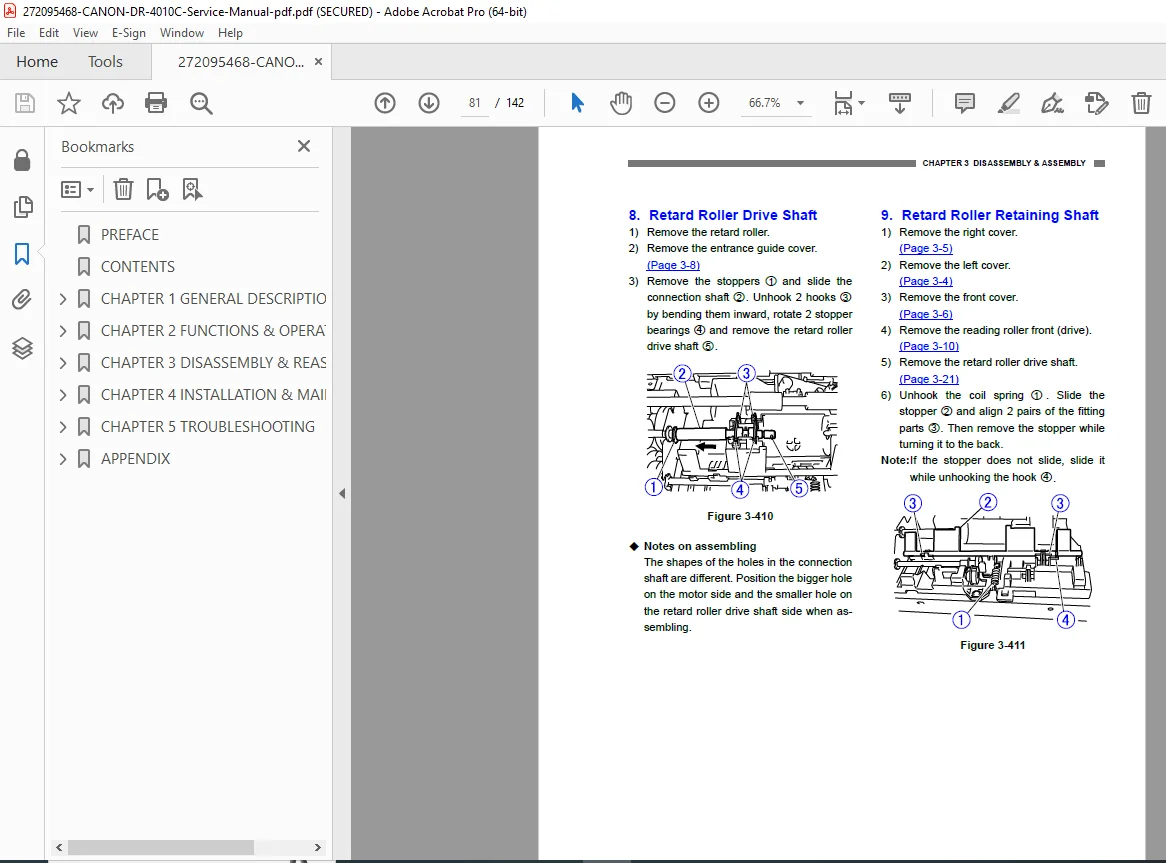
Document path removal
4.4 Optical System
CCD block removal
LED board
Calibration plate
White reference plate
4.5 Electronic System
CPU/Control PCB
Power supply board
Sensor boards
Flat cables and wiring harness
Each disassembly step includes diagrams, screws, cautions, and reassembly notes.
5. ADJUSTMENTS AND CALIBRATIONS
5.1 CCD Unit Adjustments
Alignment procedure
Gain/bias settings
Color uniformity calibration
5.2 Shading Correction
White reference plate cleaning
Calibration data writing procedure
5.3 Feed System Adjustments
Skew correction
Pickup pressure adjustment
Separation pad pressure setting
5.4 Image Quality Tests
Histogram tests
Patch code reading test
Double-feed detection tuning
6. TROUBLESHOOTING
6.1 Basic Troubleshooting Flow
No power
No scanning
Roller not rotating
No detection in ADF
PC connection issues
6.2 Error Codes & LED Indicator Meanings
Sensor errors
Feed errors
Double-feed errors
Board errors
System errors
USB communication errors
6.3 Paper Jams
Jam at entry
Jam in feed rollers
Jam at discharge
Causes & correction tables
6.4 Image Problems
Light/dark scans
Lines, streaks
Foggy image
Color imbalance
Noise patterns
Solutions & decision tree
7. MAINTENANCE
7.1 Scheduled Replacement Items
Feed rollers
Separation pads
Pickup rollers
7.2 Cleaning Procedures
Optics cleaning
Roller cleaning
Sensor and reference plate cleaning
7.3 Lubrication Points
Shafts
Bushings
Gears
8. SERVICE MODE & COMMANDS
8.1 Service Mode Entry
Key combinations
Menu flow
8.2 Functions
Error log
Roller counter reset
Sensor test mode
LED test
Motor test
Color calibration
8.3 NVRAM
Back-up procedures
Restore & reset
9. CIRCUIT DIAGRAMS
9.1 System Wiring
CPU board
Sensor boards
Motor driver
AFE (Analog Front End)
Clutch systems
Power distribution
9.2 Block Diagrams
Analog signal chain
Digital image pipeline
Power rails
10. PARTS LIST
10.1 Mechanical Parts
Rollers
Gears
Frames
Covers
10.2 Electrical Parts
PCBs
Motors
Sensors
LEDs
10.3 Assembly Exploded Views
Drive unit
ADF path
Optical path
External assembly
📁 File Details
| Field | Details |
|---|---|
| Manual Name | Canon DR-4010C Service Manual |
| Models Covered | Canon DR-4010C Document Scanner |
| Year | Official Canon release year (from service manual edition) |
| Manual PDF Quality | High-quality, text-searchable, fully bookmarked factory PDF |
| Pages | ~180 pages |