Canon iR C3100 Series / iR3100CN Service Manual – Complete PDF
Original price was: $120.00.$25.95Current price is: $25.95.
Factory Canon iR C3100 Series / iR3100CN Service Manual (over 1000 pages). Covers installation, network setup, image formation, pickup/feeding, fixing, laser and scanner systems, error code diagnostics, service mode, firmware upgrading, and full parts replacement procedures. Essential for servicing and repairing Canon iR C3100 color copier/printer systems
Description
Canon iR C3100 Series / iR3100CN Service Manual – Complete PDF DOWNLOAD
Description
This Canon iR C3100 Series / iR3100CN Service Manual is the official factory guide for technical theory, installation, maintenance, and repair of the iR C3100 full-color digital copier/printer platform. It is intended for qualified service personnel and covers all major systems: controller, reader, laser exposure, image formation, pickup/feeding, fixing, power supply, diagnostics, and firmware upgrades.
The manual opens with application notes, symbol explanations, and safety information, then walks through system construction, options, and user-side functions before diving into board-level and mechanism-level servicing.
Table of Contents
Chapter 1 – Introduction & Product Specifications
System construction and delivery accessories configurations (finishers, side deck, inner trays, card reader, heaters).
Pickup/original handling accessories, reader, cassette and side deck heater system configurations.
Printing/transmitting accessories: Super G3 Fax Board, Ethernet/UFR/PDL boards, USB interface, security and SEND options.
Names of parts: external views and full cross-section diagrams of the engine.
User modes, basic operation, user maintenance and safety, function list and system specs.
Chapter 2 – Installation
Site checks and pre-installation conditions.
Unpacking, fixing materials removal, drum unit and developing assembly installation (Cyan, Magenta, Yellow, Black).
Toner cartridge mounting, cassette setup, machine fixing and cable connections.
Initial settings: drum and developing initialization, automatic gradation correction, image position adjustment.
Network connection checks (PING, remote host tests, loopback), and network troubleshooting.
Chapter 3 – Basic Operation
Functional construction and PCB interconnections.
DC controller PCB overview.
Power-on sequence and basic sequences for full-color and mono print jobs.
Chapter 4 – Main Controller
Main/sub controller PCB construction, Expansion Bus, SRAM board, HDD.
Start-up sequence, HDD error handling (detailed E602 explanation).
Image processing flow: reader input, compression/decompression, editing, printer output, and image data paths for copier, Box, SEND, fax and PDL functions.
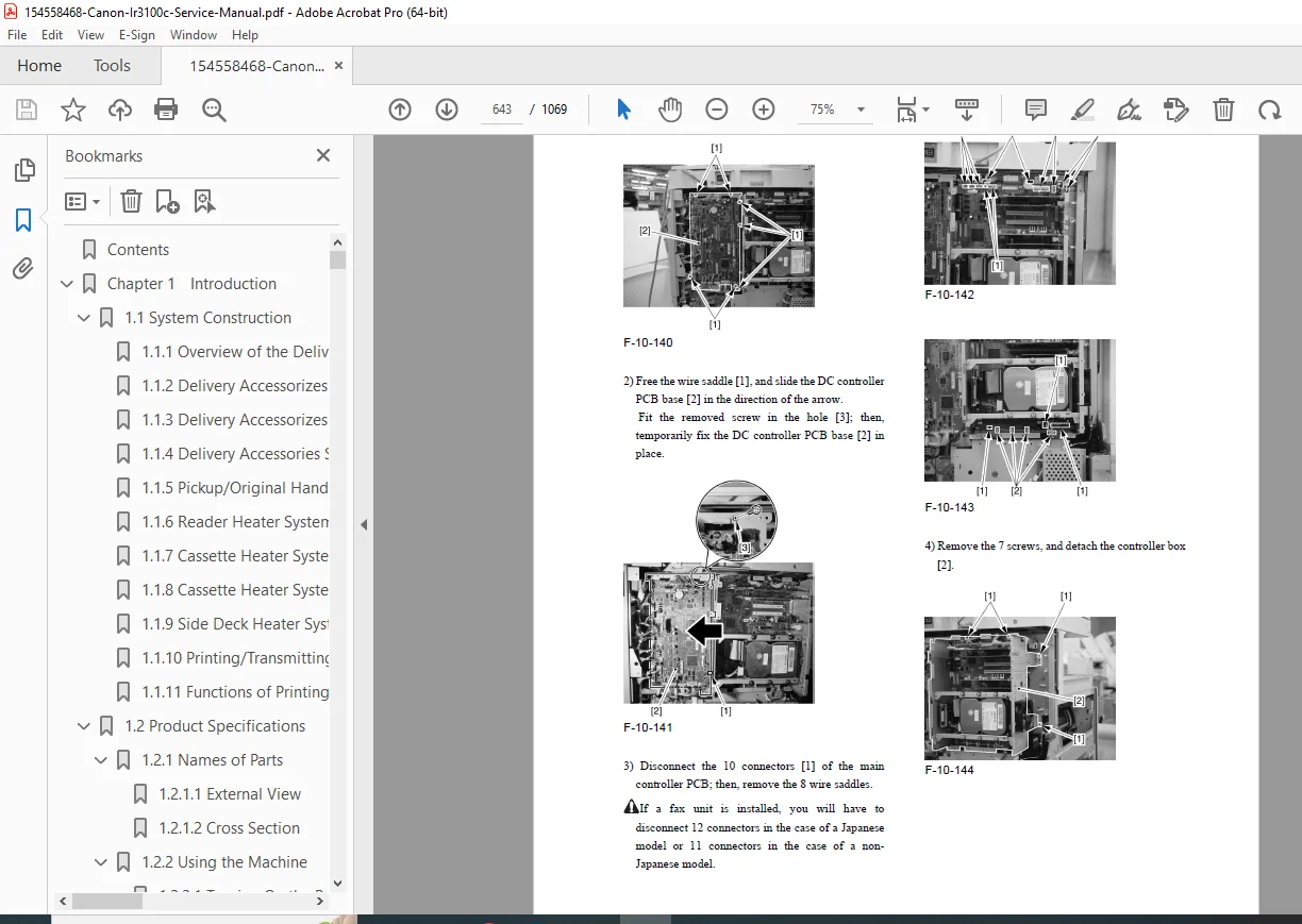
Parts replacement for the controller box, boards, Ethernet, UFR, and HDD. …
Chapter 5 – Original Exposure System (Reader)
Specifications and control mechanisms of the scanner.
Reader controller PCB and drive system, scanner motor, contact sensor, lamp control, enlargement/reduction, original size detection, dirt sensor control.
Parts replacement: copyboard glass, reader controller PCB, inverter PCB, scanner motor, sensors, reader heater.
Chapter 6 – Laser Exposure
Laser scanner specifications and control.
Laser unit removal and dust-proof glass cleaning pad procedures.
Chapter 7 – Image Formation
Image formation system specs and process description.
Two-sided placement control and image stabilization (ATR, drum film thickness, gradation density correction, auto gradation correction).
Drum unit, developing rotary and units, toner cartridge and toner supply control.
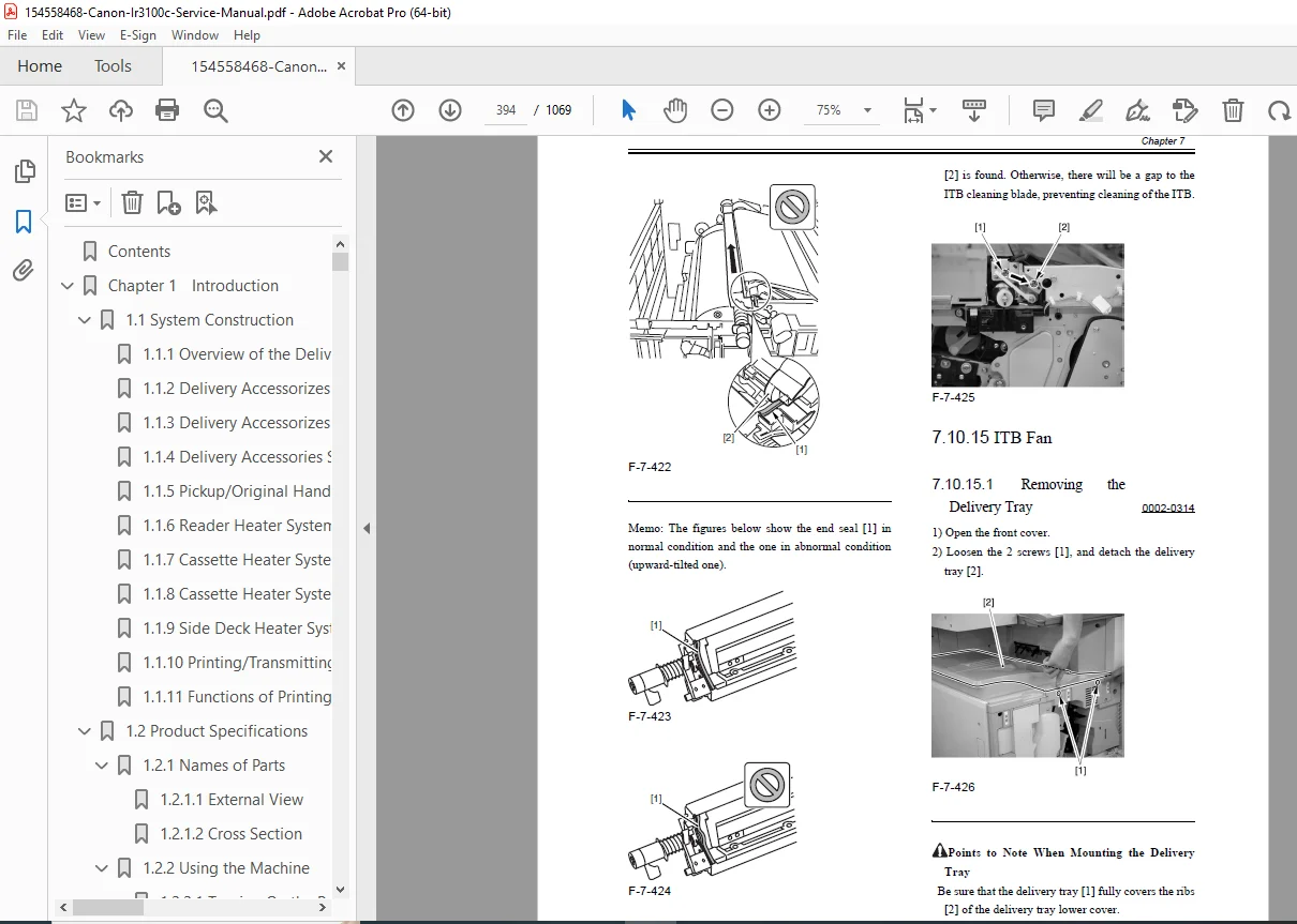
Intermediate transfer unit (ITB), transfer rollers, cleaning units, waste-toner paths, sensors and their full replacement procedures. …
Chapter 8 – Pickup / Feeding System
Copy/print basic feeding sequence and speed changes.
Jam detection (stationary and other jams).
Universal cassette setup and sensors (paper level, size, retry).
Cassette pickup units, registration unit, duplex unit, vertical path, manual feed unit, rollers, clutches, and all related sensors with detailed parts replacement steps.
Chapter 9 – Fixing System
Fixing unit specs, control mechanisms, and temperature/speed control.
Paper passage detection, thermal protection (thermistors, thermal switch, heat-retention heater), and associated error handling.
Replacement of fixing unit, rollers, thermistors, heaters, inlet/delivery guides, and sensors.
Chapter 10 – Externals and Controls
Power supply layout and DC power ratings.
Replacement procedures for option and controller power supplies, HVT and high-voltage sub PCBs, DC controller, control panel, LCD, switches, fans, and main drive motor.
Chapter 11 – Maintenance and Inspection
Periodically replaced parts and durables for reader and printer units.
Scheduled servicing flow and checklists, plus precautions for servicing work.
Chapter 12 – Standards and Adjustments
Image position standards and adjustment (cassettes, manual feed, side deck).
Post-replacement adjustments for CIS, glasses, reader PCB, laser unit, ITB, drum, developing units, transfer rollers and fixing components.
Electrical adjustments after replacing controller, SRAM, HDD, HVT, and feed components.
Chapter 13 – Correcting Faulty Images
Initial checks (environment, paper, durables).
Test prints (gradation, halftone, grids, MCYBk patterns).
Image fault troubleshooting, feeding faults, malfunction and jam analysis.
Outline of electrical components: clutches/solenoids, motors, sensors, lamps, PCBs, LEDs and test pins.
Chapter 14 – Self Diagnosis
Full error code table and detailed descriptions for E000, E001, E002, E010, E602, and many others, with causes and corrective actions.
Chapter 15 – Service Mode
Service mode structure, entry/exit, backup, display modes, I/O checks, adjustment items, operation/inspection functions, option settings, and test prints.
Chapter 16 – Upgrading
Version upgrade process, Service Support Tool (SST) usage, network interface with SST, HDD formatting, system software, RUI, BOOT, DCON/RCON and G3 fax software download/upload procedures. e…
Chapter 17 – Service Tools
Special tools, solvents and oils recommended for service work.
📄 File Details (for your product box)
| Field | Details |
|---|---|
| Manual Name | Canon iR C3100 Series / iR3100CN Service Manual |
| Models Covered | iR C3100 Series including iR3100CN (and configuration variants with optional boards/finishers) |
| Year / Edition | Service Manual dated Feb 24, 2004; copyright © 2001 Canon Inc. |
| Pages | 1069 |
| Format | |
| Manual Type | Professional Service Manual (theory, installation, maintenance, repair) |
| PDF Quality | Clear, searchable factory manual; includes diagrams, tables and error code charts |
| Main Sections | Installation, Basic Operation, Controller, Exposure, Image Formation, Pickup/Feeding, Fixing, Externals/Power, Maintenance, Adjustments, Image Fault Correction, Self Diagnosis, Service Mode, Upgrading, Service Tools |