Canon iR4570/3570/2870/2270 Service Manual PDF – DOWNLOAD
Original price was: $80.00.$36.95Current price is: $36.95.
Got a Canon iR4570, iR3570, iR2870, or iR2270 acting up? This is the official factory Service Manual PDF download – the full technician’s guide. Forget the user stuff, this digs into imageRUNNER 4570 error code guide diagnostics, repair procedures for jams, Canon iR3570 fixing unit replacement, ADF issues, and complete maintenance. Includes the essential Canon iR4570 parts list catalog. Your go-to for fixing these machines right.
Description
Canon iR4570/3570/2870/2270 Service Manual PDF DOWNLAOD (Repair/Errors/Parts)
IMAGES:
Description:
The Complete Canon imageRUNNER Technical Resource
When your Canon imageRUNNER 4570, 3570, 2870, or 2270 is down, you need real technical information – not the basic user guide. This is the Official Canon imageRUNNER 4570/3570/2870/2270 Service Manual PDF – the comprehensive technical guide straight from Canon, used by certified field service technicians worldwide. This is essential documentation for any serious Canon imageRUNNER 4570 repair and maintenance work.
Professional-Grade Technical Documentation
This manual covers everything from installation to advanced troubleshooting. You’ll get detailed installation procedures (many problems start with improper installation), complete theory of operation for each major system, preventive maintenance schedules, and most importantly, the full troubleshooting section including the comprehensive imageRUNNER 4570 error code guide.
Complete System Coverage
Need to tackle iR2870 ADF service procedures or perform a Canon iR3570 fixing unit replacement? The detailed step-by-step disassembly, reassembly, and adjustment procedures are all here. Plus, you get full access to Service Mode settings and the complete Canon imageRUNNER 4570 parts list catalog with exploded view diagrams for accurate parts identification.
All Models Covered:
- iR4570 Series (iR4570, iR4570F, iR4570N, iR4570G)
- iR3570 Series (iR3570, iR3570F, iR3570N, iR3570G)
- iR2870 Series (iR2870, iR2870F, iR2870N, iR2870G)
- iR2270 Series (iR2270, iR2270F, iR2270N, iR2270G)
Stop guessing or relying on incomplete forum information. Get the factory procedures and fix it properly the first time.
🛠️ Complete Manual Contents
Official Service Manual (1,448 Pages)
Chapter 1: Introduction
- System Outline & Configuration
- System architecture overview
- Model variations and differences
- Optional equipment compatibility
- System configuration examples
- Component layout
- Product Specifications
- General Specifications:
- Dimensions and weight
- Power requirements
- Environmental specifications
- Warm-up time
- First copy time
- General Specifications:
- Copying Specifications:
- Copy speeds (by model)
- Resolution specifications
- Magnification/reduction ratios
- Paper size support
- Duplex capabilities
- Printing Specifications:
- Print speeds
- Print resolution
- Supported page description languages
- Memory specifications
- Interface options
- Scanning Specifications:
- Scan speeds and resolution
- File format support
- Color depth
- Scanning area
- Sending Specifications:
- Email capabilities
- Network protocols
- Fax specifications (F models)
- Destination capacity
- Operation Panel Guide
- Control panel layout
- Display screen navigation
- Button functions
- Indicator meanings
- Touch panel operation (if equipped)
- Safety Information
- Electrical safety precautions
- Laser safety classifications
- High-temperature warnings
- Moving parts cautions
- Chemical handling (toner, developer)
- Installation Precautions
- Environmental requirements
- Clearance specifications
- Floor loading considerations
- Power supply requirements
Chapter 2: Installation
- Site Requirements
- Space requirements and clearances
- Environmental conditions (temperature, humidity)
- Power outlet specifications
- Network requirements
- Ventilation requirements
- Unpacking Procedures
- Carton removal
- Packing material identification
- Transit locks and protection removal
- Component inventory checklist
- Main Unit Installation
- Positioning procedures
- Leveling and stabilization
- Transit lock removal procedures
- Initial power-on checks
- Installation verification tests
- Connecting Peripherals
- Document Feeders (ADF/DADF):
- Installation procedures
- Cable connections
- Mechanical alignment
- Operation verification
- Document Feeders (ADF/DADF):
- Finishers (Inner/Booklet/Saddle):
- Installation steps
- Electrical connections
- Mechanical adjustments
- Test operation
- Paper Decks:
- Deck installation
- Paper size detection setup
- Feed roller adjustment
- Optional Equipment:
- Card readers
- Fax boards
- Additional memory
- Hard disk drives
- Software/Driver Installation
- Print driver installation
- Network scan setup
- Remote UI configuration
- Firmware updates
- Network Settings Configuration
- IP address configuration
- Subnet mask and gateway
- DNS settings
- SMTP/POP3 setup for email
- Network protocol enablement
- Security settings
Chapter 3: Basic Operation
- Construction & Function Overview
- Electrical System Overview:
- Power distribution
- Control boards and PCBs
- Communication buses
- Grounding system
- Electrical System Overview:
- Mechanical System Overview:
- Drive systems
- Paper path overview
- Process units
- Sensor locations
- Basic Sequence of Operation
- Power-on sequence
- Copy sequence flow
- Print job sequence
- Scan sequence
- Auto-duplex sequence
- Standby/sleep modes
Chapter 4: Main Controller
- Overview & Construction
- Controller board identification
- Board locations
- Component layout
- Communication interfaces
- Startup Sequence
- Boot process flow
- Initialization routines
- Self-diagnostics
- Error detection during startup
- Controller Block Diagrams
- System architecture
- Data flow diagrams
- Control signal routing
- Interface connections
- Memory Systems
- Boot ROM:
- Function and contents
- Update procedures
- Boot ROM:
- SDRAM:
- Capacity and allocation
- Image buffer usage
- Print job spooling
- HDD (Hard Disk Drive):
- Capacity specifications
- Partition structure
- Job storage
- Security features
- HDD replacement procedures
- Image Processing
- Image data flow
- Resolution conversion
- Rotation and scaling
- Color processing
- Compression algorithms
Chapter 5: Original Exposure System (Scanner)
- Overview & Construction
- Scanner assembly layout
- Optical path diagram
- CCD/CIS sensor details
- Light source specifications
- Basic Sequence
- Pre-scan operations
- Scanning sequence
- Home position return
- ADF document handling
- Components
- Motors:
- Scanner drive motor
- Motor specifications
- Drive belt routing
- Motors:
- Sensors:
- Home position sensor
- Document size detection
- ADF sensors
- PCBs:
- Reader controller board
- Sensor board
- ADF control board
- Disassembly & Assembly
- Scanner Unit Removal:
- Cover removal
- Cable disconnection
- Unit removal steps
- Installation procedures
- Scanner Unit Removal:
- Reader Controller PCB:
- PCB location
- Removal procedures
- Connector identification
- Installation and testing
- ADF Components:
- Roller replacement
- Pickup assembly service
- Separation pad replacement
- Glass cleaning access
Chapter 6: Laser Exposure System
- Overview & Construction
- Laser scanner unit layout
- Polygon mirror assembly
- Lens and mirror system
- Beam detect sensor
- Basic Sequence & Control
- Laser modulation
- Polygon motor startup
- BD signal generation
- Beam position control
- Laser Safety
- Safety classification
- Interlock systems
- Service precautions
- Beam path safety
- Components
- Laser diode specifications
- Polygon motor
- F-θ lens
- Mirrors and beam detect sensor
- Disassembly & Assembly
- Laser scanner unit removal
- Component replacement
- Beam alignment procedures
- Installation verification
Chapter 7: Image Formation System
- Overview & Construction
- Process Units:
- Photosensitive drum assembly
- Developing unit assembly
- Primary charging assembly
- Process Units:
- Transfer System:
- Intermediate Transfer Belt (ITB)
- Primary transfer roller
- Secondary transfer assembly
- Cleaning Systems:
- Drum cleaning blade
- Transfer belt cleaning
- Waste toner collection
- Basic Sequence
- Charging Process:
- Primary charging operation
- Voltage specifications
- Charging Process:
- Developing Process:
- Toner application
- Development bias control
- Developer unit operation
- Transfer Process:
- Primary transfer to ITB
- Secondary transfer to paper
- Transfer voltage control
- Cleaning Process:
- Drum cleaning sequence
- Belt cleaning operation
- Waste toner handling
- Fixing Process:
- (Covered in Chapter 9)
- Disassembly & Assembly
- Drum Unit:
- Cartridge removal
- Drum replacement
- Cleaning blade replacement
- Primary charger service
- Installation procedures
- Drum Unit:
- Developing Unit:
- Developer cartridge removal
- Toner supply system
- Developer mixing paddle
- Magnetic roller service
- Installation and checks
- Transfer Belt Unit:
- ITB assembly removal
- Belt replacement
- Roller cleaning
- Tension adjustment
- Installation procedures
- Adjustments
- Process control adjustments
- Density calibration
- Transfer voltage optimization
- Image registration
Chapter 8: Pickup/Feeding System
- Overview & Construction
- Paper Sources:
- Standard cassettes (capacity)
- Optional paper decks
- Manual feed tray
- Bypass tray
- Paper Sources:
- Paper Path Overview:
- Registration assembly
- Vertical transport
- Duplex unit
- Output paths
- Basic Sequence & Paper Path
- Pickup sequence
- Registration timing
- Feed roller operation
- Duplex reversal
- Output selection
- Components
- Motors:
- Pickup motor
- Feed motor
- Registration motor
- Motors:
- Clutches:
- Cassette clutches
- Path selection clutches
- Sensors:
- Paper detection sensors
- Size detection sensors
- Registration sensors
- Jam detection sensors
- PCBs:
- Feed control board
- Deck control board
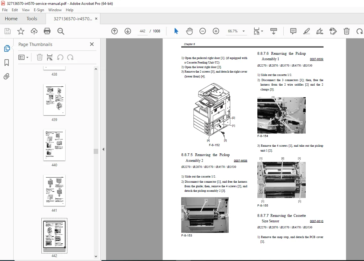
- Disassembly & Assembly
- Pickup Units:
- Cassette pickup roller replacement
- Feed roller replacement
- Separation pad replacement
- Spring tension adjustment
- Pickup Units:
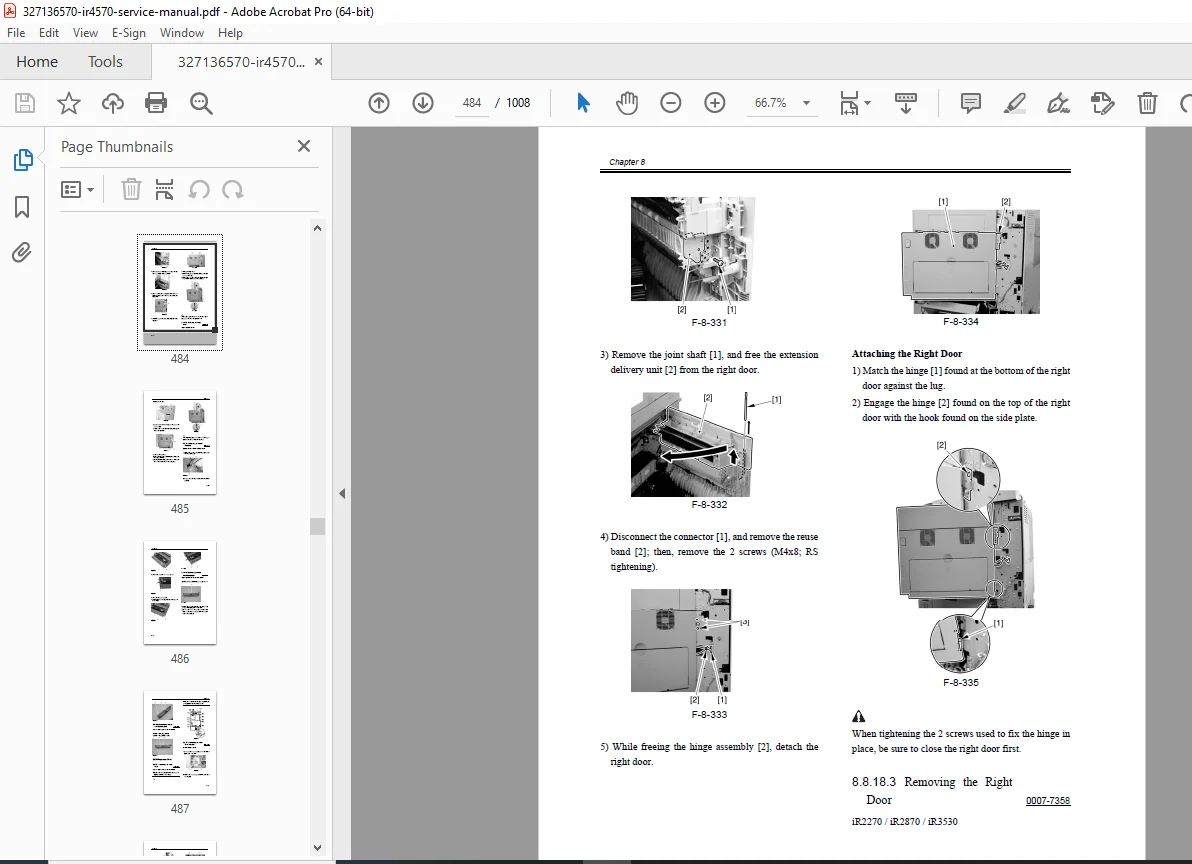
- Vertical Path Units:
- Feed roller access
- Sensor replacement
- Path guide adjustment
- Duplexing Unit:
- Duplex unit removal
- Roller replacement
- Flapper solenoid service
- Path verification
- Adjustments
- Feed timing adjustments
- Registration timing
- Skew correction
- Paper size detection calibration
Chapter 9: Fixing System
- Overview & Construction
- Fixing Unit Assembly:
- Upper fixing roller (heating)
- Lower pressure roller
- Heater lamp specifications
- Thermistor locations
- Fixing Unit Assembly:
- Temperature Control:
- PID control system
- Temperature zones
- Safety thermostat
- Basic Sequence
- Warm-up sequence
- Temperature stabilization
- Fixing pressure application
- Fixing roller rotation
- Exit sensor detection
- Components
- Motors:
- Fixing drive motor
- Motor specifications
- Motors:
- Sensors:
- Thermistors (main, sub)
- Paper exit sensor
- Safety thermostat
- PCBs:
- Fixing control board
- AC driver board
- Disassembly & Assembly
- Fixing Unit Removal:
- Safety precautions (high temperature)
- Cover removal
- Electrical disconnection
- Mechanical release
- Unit removal steps
- Installation procedures
- Fixing Unit Removal:
- Component Replacement:
- Upper fixing roller replacement
- Lower pressure roller replacement
- Heater lamp replacement
- Thermistor replacement
- Pressure spring adjustment
- Cleaning web roller service
- Adjustments & Calibration
- Temperature calibration
- Fixing pressure adjustment
- Nip width verification
- Exit timing adjustment
Chapter 10: Externals and Controls
- External Covers Removal
- Front cover removal sequence
- Side cover removal
- Top cover access
- Rear cover removal
- Inner covers and shields
- Screw locations and types
- Control Panel
- Control panel removal
- Display replacement
- Button/keypad service
- Touch panel replacement (if equipped)
- Cable routing
- Power Supply System
- Overview:
- AC input and distribution
- DC power supply units
- Voltage specifications
- Overview:
- PCBs:
- Main power supply board
- DC power supply board
- AC driver boards
- Voltage regulator modules
- Drive System
- Main drive motor
- Gear train layout
- Belt routing
- Clutch locations
- Drive transmission
Chapter 11: Maintenance and Inspection
- Periodically Replaced Parts List
- Recommended replacement intervals
- Parts by mileage/time
- Component life expectancy
- Part numbers for consumables
- Consumables List
- Toner cartridges
- Staples (finisher models)
- Cleaning supplies
- Durables List
- Drum units
- Transfer belt
- Fixing unit components
- Feed rollers
- Separation pads
- Scheduled Maintenance Chart
- Daily maintenance tasks
- Weekly maintenance tasks
- Monthly maintenance tasks
- Quarterly maintenance tasks
- Annual maintenance tasks
- Major overhaul intervals
- Maintenance Procedures
- Cleaning procedures (glass, rollers, paths)
- Lubrication points
- Inspection checklists
- Adjustment verification
- Performance testing
Chapter 12: Troubleshooting
- Initial Checks
- Visual inspection checklist
- Error code retrieval
- Counter check
- Log analysis
- Symptom Analysis
- Systematic troubleshooting approach
- Flowcharts by symptom
- Component isolation techniques
- Error Code Table & Solutions
- Complete error code list
- Error descriptions
- Probable causes
- Corrective actions
- Related components
- Service mode checks
- Parts to inspect/replace
- Jam Detection & Clearance Guides
- Jam code meanings
- Jam location identification
- Clearance procedures by location
- Sensor verification after clearance
- Recurring jam diagnosis
- Image Quality Troubleshooting
- Streaks/Lines:
- Vertical lines
- Horizontal lines
- Periodic defects
- Random marks
- Streaks/Lines:
- Spots/Dots:
- White spots
- Black spots
- Toner scatter
- Density Issues:
- Light copies/prints
- Dark copies/prints
- Uneven density
- Background fog
- Paper Issues:
- Skewing
- Wrinkling
- Curling
- Poor fixing
- Registration Problems:
- Top margin errors
- Side margin errors
- Duplex misalignment
- Electrical Fault Finding
- Power Issues:
- No power
- Intermittent power
- Breaker trips
- Power Issues:
- Sensor Faults:
- Sensor testing procedures
- Voltage measurements
- Signal tracing
- Motor Problems:
- Motor won’t run
- Motor runs continuously
- Speed issues
- PCB Diagnosis:
- Board-level troubleshooting
- Connector checks
- Voltage verification
- Signal path testing
- Service Tools
- Diagnostic tool descriptions
- Test pattern printing
- Calibration tools
- Measurement equipment needed
Chapter 13: Service Mode
- Overview
- Service Mode purpose
- Security considerations
- Data backup before changes
- How to Enter Service Mode
- Key sequence
- Password requirements (if any)
- Navigation instructions
- Exit procedures
- Function Descriptions
- Display Functions:
- Counter displays
- Status displays
- Error history
- Sensor status
- Display Functions:
- I/O Functions:
- Input signal check
- Output signal test
- Sensor status monitoring
- Motor drive test
- Adjust Functions:
- Registration adjustments
- Density adjustments
- Color balance (if applicable)
- Transfer voltage
- Fixing temperature
- Function Settings:
- Feature enable/disable
- Default value changes
- Timer settings
- Mode configurations
- Option Settings:
- Optional equipment registration
- Paper deck configuration
- Finisher setup
- Interface settings
- Counter Functions:
- Total counter
- Print counter
- Copy counter
- Component life counters
- Counter reset procedures
- Detailed Setting Tables
- Complete service mode menu structure
- Parameter descriptions
- Default values
- Allowable ranges
- Effect of changes
- Adjustment Procedures
- Step-by-step adjustment guides
- Required test patterns
- Measurement procedures
- Verification methods
- Fine-tuning tips
Chapter 14: Installation (Options)
- Document Feeder Installation
- DADF (Duplex Auto Document Feeder) installation
- Standard ADF installation
- Cable routing
- Mechanical connection
- Setting registration
- Test operation
- Finisher Installation
- Inner Finisher:
- Installation steps
- Staple cartridge loading
- Adjustment procedures
- Inner Finisher:
- Booklet Finisher:
- Installation procedures
- Saddle stitch setup
- Folding unit adjustment
- Saddle Finisher:
- Mechanical installation
- Electrical connections
- Test booklet creation
- Paper Deck Installation
- Deck positioning and connection
- Lift motor adjustment
- Paper size detection setup
- Feed timing adjustment
- Card Reader Installation
- Mounting procedures
- Interface connection
- Software setup
- Access control configuration
- Fax Board Installation
- Board installation in controller
- Telephone line connection
- Fax settings configuration
- Test transmission
- Additional Options
- Memory upgrades
- HDD replacement
- Network interface cards
- Wireless adapters
Appendix
- General Circuit Diagram
- Overall electrical schematic
- Power distribution diagram
- Major component interconnections
- Wiring Diagrams
- Detailed wiring by section
- Cable color codes
- Connector pin-outs
- Harness routing
- Ground point locations
- Parts Catalog / List
- Exploded View Diagrams:
- Main unit assembly
- Scanner assembly
- Laser unit
- Process units
- Pickup/feed assemblies
- Fixing unit
- Optional equipment
- Exploded View Diagrams:
- Parts Lists:
- Part numbers
- Part descriptions
- Quantity per unit
- Reference designators
- Superseded part cross-reference
- Ordering information
📄 Technical Specifications
- Manual Name: Canon imageRUNNER 4570 / 3570 / 2870 / 2270 Series Service Manual
- Models Covered:
- iR4570 Series: iR4570, iR4570F, iR4570N, iR4570G
- iR3570 Series: iR3570, iR3570F, iR3570N, iR3570G
- iR2870 Series: iR2870, iR2870F, iR2870N, iR2870G
- iR2270 Series: iR2270, iR2270F, iR2270N, iR2270G
- Model Suffixes:
- Base model: Standard configuration
- F: Fax capability included
- N: Network-ready configuration
- G: Global/International variant
- Publication: Internal Canon factory document
- Format: Good quality scan, fully searchable, printable PDF with bookmarks
- Pages: 1,448
- Language: English
- Quality: Clear diagrams and text, professional factory documentation
Who Needs This Manual?
This comprehensive service manual is essential for:
- Canon Authorized Service Technicians (certified technicians)
- Independent Copier Service Companies (multi-brand specialists)
- In-House Corporate IT/Facilities Departments (large fleet management)
- Print Shop Technical Staff (production environment maintenance)
- Office Equipment Repair Businesses
- Biomedical/Technical Equipment Technicians (expanding to copier service)
- MFP Service Training Instructors
- Parts Suppliers and Resellers (accurate parts identification)
I’ll format this Canon imageRUNNER service manual description into a professional, well-structured product listing:
Formatted Product Description
Main Product Title:
Canon imageRUNNER 4570 3570 2870 2270 Service Manual PDF – Official Factory Repair & Troubleshooting Guide
Short Description (for product listing/excerpt):
Official Canon imageRUNNER 4570/3570/2870/2270 Series Service Manual. Complete factory documentation covering installation, operation theory, maintenance, troubleshooting with error codes, disassembly/reassembly, service mode, and parts catalog. Used by Canon field technicians. 1,448 pages. Essential for professional copier repair.
Full Product Description:
The Complete Canon imageRUNNER Technical Resource
When your Canon imageRUNNER 4570, 3570, 2870, or 2270 is down, you need real technical information – not the basic user guide. This is the Official Canon imageRUNNER 4570/3570/2870/2270 Service Manual PDF – the comprehensive technical guide straight from Canon, used by certified field service technicians worldwide. This is essential documentation for any serious Canon imageRUNNER 4570 repair and maintenance work.
Professional-Grade Technical Documentation
This manual covers everything from installation to advanced troubleshooting. You’ll get detailed installation procedures (many problems start with improper installation), complete theory of operation for each major system, preventive maintenance schedules, and most importantly, the full troubleshooting section including the comprehensive imageRUNNER 4570 error code guide.
Complete System Coverage
Need to tackle iR2870 ADF service procedures or perform a Canon iR3570 fixing unit replacement? The detailed step-by-step disassembly, reassembly, and adjustment procedures are all here. Plus, you get full access to Service Mode settings and the complete Canon imageRUNNER 4570 parts list catalog with exploded view diagrams for accurate parts identification.
All Models Covered:
- iR4570 Series (iR4570, iR4570F, iR4570N, iR4570G)
- iR3570 Series (iR3570, iR3570F, iR3570N, iR3570G)
- iR2870 Series (iR2870, iR2870F, iR2870N, iR2870G)
- iR2270 Series (iR2270, iR2270F, iR2270N, iR2270G)
Stop guessing or relying on incomplete forum information. Get the factory procedures and fix it properly the first time.
🛠️ Complete Manual Contents
Official Service Manual (1,448 Pages)
Chapter 1: Introduction
- System Outline & Configuration
- System architecture overview
- Model variations and differences
- Optional equipment compatibility
- System configuration examples
- Component layout
- Product Specifications
- General Specifications:
- Dimensions and weight
- Power requirements
- Environmental specifications
- Warm-up time
- First copy time
- Copying Specifications:
- Copy speeds (by model)
- Resolution specifications
- Magnification/reduction ratios
- Paper size support
- Duplex capabilities
- Printing Specifications:
- Print speeds
- Print resolution
- Supported page description languages
- Memory specifications
- Interface options
- Scanning Specifications:
- Scan speeds and resolution
- File format support
- Color depth
- Scanning area
- Sending Specifications:
- Email capabilities
- Network protocols
- Fax specifications (F models)
- Destination capacity
- General Specifications:
- Operation Panel Guide
- Control panel layout
- Display screen navigation
- Button functions
- Indicator meanings
- Touch panel operation (if equipped)
- Safety Information
- Electrical safety precautions
- Laser safety classifications
- High-temperature warnings
- Moving parts cautions
- Chemical handling (toner, developer)
- Installation Precautions
- Environmental requirements
- Clearance specifications
- Floor loading considerations
- Power supply requirements
Chapter 2: Installation
- Site Requirements
- Space requirements and clearances
- Environmental conditions (temperature, humidity)
- Power outlet specifications
- Network requirements
- Ventilation requirements
- Unpacking Procedures
- Carton removal
- Packing material identification
- Transit locks and protection removal
- Component inventory checklist
- Main Unit Installation
- Positioning procedures
- Leveling and stabilization
- Transit lock removal procedures
- Initial power-on checks
- Installation verification tests
- Connecting Peripherals
- Document Feeders (ADF/DADF):
- Installation procedures
- Cable connections
- Mechanical alignment
- Operation verification
- Finishers (Inner/Booklet/Saddle):
- Installation steps
- Electrical connections
- Mechanical adjustments
- Test operation
- Paper Decks:
- Deck installation
- Paper size detection setup
- Feed roller adjustment
- Optional Equipment:
- Card readers
- Fax boards
- Additional memory
- Hard disk drives
- Document Feeders (ADF/DADF):
- Software/Driver Installation
- Print driver installation
- Network scan setup
- Remote UI configuration
- Firmware updates
- Network Settings Configuration
- IP address configuration
- Subnet mask and gateway
- DNS settings
- SMTP/POP3 setup for email
- Network protocol enablement
- Security settings
Chapter 3: Basic Operation
- Construction & Function Overview
- Electrical System Overview:
- Power distribution
- Control boards and PCBs
- Communication buses
- Grounding system
- Mechanical System Overview:
- Drive systems
- Paper path overview
- Process units
- Sensor locations
- Electrical System Overview:
- Basic Sequence of Operation
- Power-on sequence
- Copy sequence flow
- Print job sequence
- Scan sequence
- Auto-duplex sequence
- Standby/sleep modes
Chapter 4: Main Controller
- Overview & Construction
- Controller board identification
- Board locations
- Component layout
- Communication interfaces
- Startup Sequence
- Boot process flow
- Initialization routines
- Self-diagnostics
- Error detection during startup
- Controller Block Diagrams
- System architecture
- Data flow diagrams
- Control signal routing
- Interface connections
- Memory Systems
- Boot ROM:
- Function and contents
- Update procedures
- SDRAM:
- Capacity and allocation
- Image buffer usage
- Print job spooling
- HDD (Hard Disk Drive):
- Capacity specifications
- Partition structure
- Job storage
- Security features
- HDD replacement procedures
- Boot ROM:
- Image Processing
- Image data flow
- Resolution conversion
- Rotation and scaling
- Color processing
- Compression algorithms
Chapter 5: Original Exposure System (Scanner)
- Overview & Construction
- Scanner assembly layout
- Optical path diagram
- CCD/CIS sensor details
- Light source specifications
- Basic Sequence
- Pre-scan operations
- Scanning sequence
- Home position return
- ADF document handling
- Components
- Motors:
- Scanner drive motor
- Motor specifications
- Drive belt routing
- Sensors:
- Home position sensor
- Document size detection
- ADF sensors
- PCBs:
- Reader controller board
- Sensor board
- ADF control board
- Motors:
- Disassembly & Assembly
- Scanner Unit Removal:
- Cover removal
- Cable disconnection
- Unit removal steps
- Installation procedures
- Reader Controller PCB:
- PCB location
- Removal procedures
- Connector identification
- Installation and testing
- ADF Components:
- Roller replacement
- Pickup assembly service
- Separation pad replacement
- Glass cleaning access
- Scanner Unit Removal:
Chapter 6: Laser Exposure System
- Overview & Construction
- Laser scanner unit layout
- Polygon mirror assembly
- Lens and mirror system
- Beam detect sensor
- Basic Sequence & Control
- Laser modulation
- Polygon motor startup
- BD signal generation
- Beam position control
- Laser Safety
- Safety classification
- Interlock systems
- Service precautions
- Beam path safety
- Components
- Laser diode specifications
- Polygon motor
- F-θ lens
- Mirrors and beam detect sensor
- Disassembly & Assembly
- Laser scanner unit removal
- Component replacement
- Beam alignment procedures
- Installation verification
Chapter 7: Image Formation System
- Overview & Construction
- Process Units:
- Photosensitive drum assembly
- Developing unit assembly
- Primary charging assembly
- Transfer System:
- Intermediate Transfer Belt (ITB)
- Primary transfer roller
- Secondary transfer assembly
- Cleaning Systems:
- Drum cleaning blade
- Transfer belt cleaning
- Waste toner collection
- Process Units:
- Basic Sequence
- Charging Process:
- Primary charging operation
- Voltage specifications
- Developing Process:
- Toner application
- Development bias control
- Developer unit operation
- Transfer Process:
- Primary transfer to ITB
- Secondary transfer to paper
- Transfer voltage control
- Cleaning Process:
- Drum cleaning sequence
- Belt cleaning operation
- Waste toner handling
- Fixing Process:
- (Covered in Chapter 9)
- Charging Process:
- Disassembly & Assembly
- Drum Unit:
- Cartridge removal
- Drum replacement
- Cleaning blade replacement
- Primary charger service
- Installation procedures
- Developing Unit:
- Developer cartridge removal
- Toner supply system
- Developer mixing paddle
- Magnetic roller service
- Installation and checks
- Transfer Belt Unit:
- ITB assembly removal
- Belt replacement
- Roller cleaning
- Tension adjustment
- Installation procedures
- Drum Unit:
- Adjustments
- Process control adjustments
- Density calibration
- Transfer voltage optimization
- Image registration
Chapter 8: Pickup/Feeding System
- Overview & Construction
- Paper Sources:
- Standard cassettes (capacity)
- Optional paper decks
- Manual feed tray
- Bypass tray
- Paper Path Overview:
- Registration assembly
- Vertical transport
- Duplex unit
- Output paths
- Paper Sources:
- Basic Sequence & Paper Path
- Pickup sequence
- Registration timing
- Feed roller operation
- Duplex reversal
- Output selection
- Components
- Motors:
- Pickup motor
- Feed motor
- Registration motor
- Clutches:
- Cassette clutches
- Path selection clutches
- Sensors:
- Paper detection sensors
- Size detection sensors
- Registration sensors
- Jam detection sensors
- PCBs:
- Feed control board
- Deck control board
- Motors:
- Disassembly & Assembly
- Pickup Units:
- Cassette pickup roller replacement
- Feed roller replacement
- Separation pad replacement
- Spring tension adjustment
- Vertical Path Units:
- Feed roller access
- Sensor replacement
- Path guide adjustment
- Duplexing Unit:
- Duplex unit removal
- Roller replacement
- Flapper solenoid service
- Path verification
- Pickup Units:
- Adjustments
- Feed timing adjustments
- Registration timing
- Skew correction
- Paper size detection calibration
Chapter 9: Fixing System
- Overview & Construction
- Fixing Unit Assembly:
- Upper fixing roller (heating)
- Lower pressure roller
- Heater lamp specifications
- Thermistor locations
- Temperature Control:
- PID control system
- Temperature zones
- Safety thermostat
- Fixing Unit Assembly:
- Basic Sequence
- Warm-up sequence
- Temperature stabilization
- Fixing pressure application
- Fixing roller rotation
- Exit sensor detection
- Components
- Motors:
- Fixing drive motor
- Motor specifications
- Sensors:
- Thermistors (main, sub)
- Paper exit sensor
- Safety thermostat
- PCBs:
- Fixing control board
- AC driver board
- Motors:
- Disassembly & Assembly
- Fixing Unit Removal:
- Safety precautions (high temperature)
- Cover removal
- Electrical disconnection
- Mechanical release
- Unit removal steps
- Installation procedures
- Component Replacement:
- Upper fixing roller replacement
- Lower pressure roller replacement
- Heater lamp replacement
- Thermistor replacement
- Pressure spring adjustment
- Cleaning web roller service
- Fixing Unit Removal:
- Adjustments & Calibration
- Temperature calibration
- Fixing pressure adjustment
- Nip width verification
- Exit timing adjustment
Chapter 10: Externals and Controls
- External Covers Removal
- Front cover removal sequence
- Side cover removal
- Top cover access
- Rear cover removal
- Inner covers and shields
- Screw locations and types
- Control Panel
- Control panel removal
- Display replacement
- Button/keypad service
- Touch panel replacement (if equipped)
- Cable routing
- Power Supply System
- Overview:
- AC input and distribution
- DC power supply units
- Voltage specifications
- PCBs:
- Main power supply board
- DC power supply board
- AC driver boards
- Voltage regulator modules
- Overview:
- Drive System
- Main drive motor
- Gear train layout
- Belt routing
- Clutch locations
- Drive transmission
Chapter 11: Maintenance and Inspection
- Periodically Replaced Parts List
- Recommended replacement intervals
- Parts by mileage/time
- Component life expectancy
- Part numbers for consumables
- Consumables List
- Toner cartridges
- Staples (finisher models)
- Cleaning supplies
- Durables List
- Drum units
- Transfer belt
- Fixing unit components
- Feed rollers
- Separation pads
- Scheduled Maintenance Chart
- Daily maintenance tasks
- Weekly maintenance tasks
- Monthly maintenance tasks
- Quarterly maintenance tasks
- Annual maintenance tasks
- Major overhaul intervals
- Maintenance Procedures
- Cleaning procedures (glass, rollers, paths)
- Lubrication points
- Inspection checklists
- Adjustment verification
- Performance testing
Chapter 12: Troubleshooting
- Initial Checks
- Visual inspection checklist
- Error code retrieval
- Counter check
- Log analysis
- Symptom Analysis
- Systematic troubleshooting approach
- Flowcharts by symptom
- Component isolation techniques
- Error Code Table & Solutions
- Complete error code list
- Error descriptions
- Probable causes
- Corrective actions
- Related components
- Service mode checks
- Parts to inspect/replace
- Jam Detection & Clearance Guides
- Jam code meanings
- Jam location identification
- Clearance procedures by location
- Sensor verification after clearance
- Recurring jam diagnosis
- Image Quality Troubleshooting
- Streaks/Lines:
- Vertical lines
- Horizontal lines
- Periodic defects
- Random marks
- Spots/Dots:
- White spots
- Black spots
- Toner scatter
- Density Issues:
- Light copies/prints
- Dark copies/prints
- Uneven density
- Background fog
- Paper Issues:
- Skewing
- Wrinkling
- Curling
- Poor fixing
- Registration Problems:
- Top margin errors
- Side margin errors
- Duplex misalignment
- Streaks/Lines:
- Electrical Fault Finding
- Power Issues:
- No power
- Intermittent power
- Breaker trips
- Sensor Faults:
- Sensor testing procedures
- Voltage measurements
- Signal tracing
- Motor Problems:
- Motor won’t run
- Motor runs continuously
- Speed issues
- PCB Diagnosis:
- Board-level troubleshooting
- Connector checks
- Voltage verification
- Signal path testing
- Power Issues:
- Service Tools
- Diagnostic tool descriptions
- Test pattern printing
- Calibration tools
- Measurement equipment needed
Chapter 13: Service Mode
- Overview
- Service Mode purpose
- Security considerations
- Data backup before changes
- How to Enter Service Mode
- Key sequence
- Password requirements (if any)
- Navigation instructions
- Exit procedures
- Function Descriptions
- Display Functions:
- Counter displays
- Status displays
- Error history
- Sensor status
- I/O Functions:
- Input signal check
- Output signal test
- Sensor status monitoring
- Motor drive test
- Adjust Functions:
- Registration adjustments
- Density adjustments
- Color balance (if applicable)
- Transfer voltage
- Fixing temperature
- Function Settings:
- Feature enable/disable
- Default value changes
- Timer settings
- Mode configurations
- Option Settings:
- Optional equipment registration
- Paper deck configuration
- Finisher setup
- Interface settings
- Counter Functions:
- Total counter
- Print counter
- Copy counter
- Component life counters
- Counter reset procedures
- Display Functions:
- Detailed Setting Tables
- Complete service mode menu structure
- Parameter descriptions
- Default values
- Allowable ranges
- Effect of changes
- Adjustment Procedures
- Step-by-step adjustment guides
- Required test patterns
- Measurement procedures
- Verification methods
- Fine-tuning tips
Chapter 14: Installation (Options)
- Document Feeder Installation
- DADF (Duplex Auto Document Feeder) installation
- Standard ADF installation
- Cable routing
- Mechanical connection
- Setting registration
- Test operation
- Finisher Installation
- Inner Finisher:
- Installation steps
- Staple cartridge loading
- Adjustment procedures
- Booklet Finisher:
- Installation procedures
- Saddle stitch setup
- Folding unit adjustment
- Saddle Finisher:
- Mechanical installation
- Electrical connections
- Test booklet creation
- Inner Finisher:
- Paper Deck Installation
- Deck positioning and connection
- Lift motor adjustment
- Paper size detection setup
- Feed timing adjustment
- Card Reader Installation
- Mounting procedures
- Interface connection
- Software setup
- Access control configuration
- Fax Board Installation
- Board installation in controller
- Telephone line connection
- Fax settings configuration
- Test transmission
- Additional Options
- Memory upgrades
- HDD replacement
- Network interface cards
- Wireless adapters
Appendix
- General Circuit Diagram
- Overall electrical schematic
- Power distribution diagram
- Major component interconnections
- Wiring Diagrams
- Detailed wiring by section
- Cable color codes
- Connector pin-outs
- Harness routing
- Ground point locations
- Parts Catalog / List
- Exploded View Diagrams:
- Main unit assembly
- Scanner assembly
- Laser unit
- Process units
- Pickup/feed assemblies
- Fixing unit
- Optional equipment
- Parts Lists:
- Part numbers
- Part descriptions
- Quantity per unit
- Reference designators
- Superseded part cross-reference
- Ordering information
- Exploded View Diagrams:
📄 Technical Specifications
- Manual Name: Canon imageRUNNER 4570 / 3570 / 2870 / 2270 Series Service Manual
- Models Covered:
- iR4570 Series: iR4570, iR4570F, iR4570N, iR4570G
- iR3570 Series: iR3570, iR3570F, iR3570N, iR3570G
- iR2870 Series: iR2870, iR2870F, iR2870N, iR2870G
- iR2270 Series: iR2270, iR2270F, iR2270N, iR2270G
- Model Suffixes:
- Base model: Standard configuration
- F: Fax capability included
- N: Network-ready configuration
- G: Global/International variant
- Publication: Internal Canon factory document
- Format: Good quality scan, fully searchable, printable PDF with bookmarks
- Pages: 1,448
- Language: English
- Quality: Clear diagrams and text, professional factory documentation
Who Needs This Manual?
This comprehensive service manual is essential for:
- Canon Authorized Service Technicians (certified technicians)
- Independent Copier Service Companies (multi-brand specialists)
- In-House Corporate IT/Facilities Departments (large fleet management)
- Print Shop Technical Staff (production environment maintenance)
- Office Equipment Repair Businesses
- Biomedical/Technical Equipment Technicians (expanding to copier service)
- MFP Service Training Instructors
- Parts Suppliers and Resellers (accurate parts identification)
Why This Manual is Critical
Factory-Level Technical Knowledge:
- Official Canon engineering documentation
- Exact specifications and tolerances
- Correct service procedures approved by Canon
- Complete theory of operation
- Professional troubleshooting methodology
Comprehensive Error Code Coverage:
- Complete error code table with descriptions
- Root cause analysis for each code
- Step-by-step corrective actions
- Related components to check
- Service mode diagnostics
Complete Parts Information:
- 1,448 pages of detailed technical content
- Exploded view diagrams for every assembly
- Accurate part numbers
- Parts location identification
- Supersession information
Service Mode Access:
- Complete service mode documentation
- Adjustment procedures with parameters
- Counter management
- Feature enable/disable
- Diagnostic utilities
Installation & Integration:
- Proper installation procedures prevent future problems
- Optional equipment integration
- Network configuration
- Software setup
Common Service Scenarios Covered:
✅ Paper Jams – Detailed jam location diagnosis and clearance
✅ Image Quality Issues – Systematic troubleshooting for all defects
✅ Error Codes – Complete error code list with solutions
✅ ADF Problems – Full ADF service and roller replacement
✅ Fixing Unit Failure – Complete fixing assembly service
✅ Transfer Issues – ITB and transfer roller service
✅ Network Problems – Configuration and troubleshooting
✅ Drum/Developer Replacement – Proper installation procedures
✅ Finisher Malfunctions – Stapling and sorting problems
✅ Scanner Issues – Optical system service and calibration
✅ Control Panel Errors – Display and button replacement
✅ Power Supply Failures – Electrical system diagnosis
⚠️ Important Notice
This is a professional-grade factory service manual intended for qualified technicians with experience in copier/MFP service and repair. Working on these systems requires knowledge of electrical systems, mechanical assemblies, laser safety, and high-voltage/high-temperature components. Always follow proper safety procedures including lockout/tagout, proper grounding, and manufacturer safety guidelines.
Technical Note: This service manual covers multiple models in the imageRUNNER series (4570/3570/2870/2270). While the core systems are similar, specific procedures and parts may vary by model. Always verify model-specific information before performing service work.
Key Benefits:
✅ Official Canon Factory Documentation – Not third-party or generic information
✅ Complete Coverage – All systems, all procedures, all components
✅ 1,448 Pages of comprehensive technical information
✅ Error Code Guide – Complete troubleshooting reference
✅ Service Mode Documentation – Full adjustment and diagnostic access
✅ Parts Catalog Included – Exploded views with part numbers
✅ Wiring Diagrams – Complete electrical schematics
✅ Installation Procedures – Optional equipment integration
✅ Searchable PDF – Find information instantly
✅ Printable – Create reference copies for field work
✅ Bookmarked Navigation – Jump directly to any section
✅ Clear Diagrams – Professional factory illustrations and photos
✅ Instant Download – Start servicing immediately
Maximize Uptime, Minimize Costs
With this official service manual, you can:
- Diagnose problems accurately the first time
- Reduce service calls with proper preventive maintenance
- Order correct parts using accurate part numbers
- Perform complex repairs in-house instead of expensive service contracts
- Train technicians effectively with factory procedures
- Troubleshoot systematically using error codes and flowcharts
- Extend equipment life through proper maintenance
Instant Digital Delivery: Receive your PDF manual immediately after purchase. No shipping delays, no waiting. Download and start servicing right away.