
Case 410 and 420 Skid Steer Service Manual – Full PDF Workshop Repair Guide (Bur 6-78950)
Original price was: $55.95.$34.95Current price is: $34.95.
Complete Case 410 and 420 skid steer service manual (Bur 6-78950, February 2005). 468 pages of engine, hydrostatic drive, hydraulic, electrical, brake, axle and loader repair procedures with torque values, capacities, test pressures, wiring schematics and exploded illustrations.
Description
Case 410 and 420 Skid Steer Service Manual (Bur 6-78950)
This is the complete Case 410 and 420 skid steer service manual, published under document number Bur 6-78950 and dated February 2005. It is the same volume a shop technician works from: engine and radiator removal, hydrostatic drive service, hydraulic troubleshooting, electrical schematics, brakes, axles, chains, wheels, and the mounted loader equipment. Every procedure is written as numbered steps with the matching torque values, capacities, test pressures and exploded illustrations printed alongside.
File Details
- Manual type: Service and repair manual
- Brand: Case
- Models covered: 410 and 420 skid steer loaders
- Document number: Bur 6-78950
- Publication date: February 2005
- Language: English
- Format: PDF
- Page count: 468 pages
Chapters Covered
- General
- Engines
- Fuel Systems
- Electrical
- Power Train
- Brakes
- Hydraulics
- Mounted Equipment
General
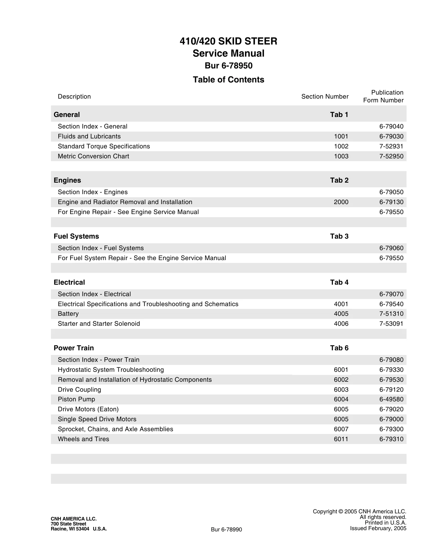
The General tab opens with fluids and lubricants: capacities for the fuel tank (83.3 litres / 22 U.S. gallons), cooling system (17 litres / 17.9 quarts), total hydraulic system (50.2 litres / 13.3 gallons) and reservoir (32.4 litres / 7.1 gallons), each chain compartment (5.7 litres / 6.0 quarts) and the engine crankcase (8.7 litres with filter change on 410 and 420 machines). It lists the recommended Case Akcela No. 1 Engine Oil in SAE 10W-30, gives an oil viscosity and temperature range chart, sets out the accepted No. 2 diesel fuel specification (API gravity, flash point, cloud point, pour point, distillation, viscosity, cetane number, water and sediment, sulphur, copper strip corrosion and ash), and then delivers a full standard torque section covering Grade 5 and Grade 8 decimal hardware, metric Grade 8.8, 10.9 and 12.9 fasteners, steel hydraulic fittings, split flange mounting bolts, O-ring face seal and O-ring boss ends, and pipe fittings with turns-from-finger-tight values. A metric to U.S. and U.S. to metric conversion chart completes the tab.
Engines
Covers radiator and engine removal and installation in full. Radiator steps walk through draining through the drain valve into a 17 litre container, loosening the cap and overflow hose, opening the heater coolant valve, then swinging the High Flow oil cooler away on its hinge latch before tipping the radiator out and pulling the upper and lower hoses. Engine removal covers tagging electrical connections, disconnecting heater hoses, removing the rear access door and its tail lamp, worklight and backup alarm wiring, pulling the hood from its pivot shafts, removing the air cleaner assembly, muffler and support rods, the fan blade and spacer, the starter and alternator wiring, the throttle linkage, the fuel lines and shut-off valve, the pump drive joint from the flywheel, and finally the front and rear engine mounts. Installation notes call for Molykote GN on the pump drive joint splines, 94 to 106 Nm (68 to 78 pound-feet) on the pump drive joint bolts and 110 to 122 Nm (80 to 90 pound-feet) on the engine mount bolts, with a refill and leak check at the end.
Electrical
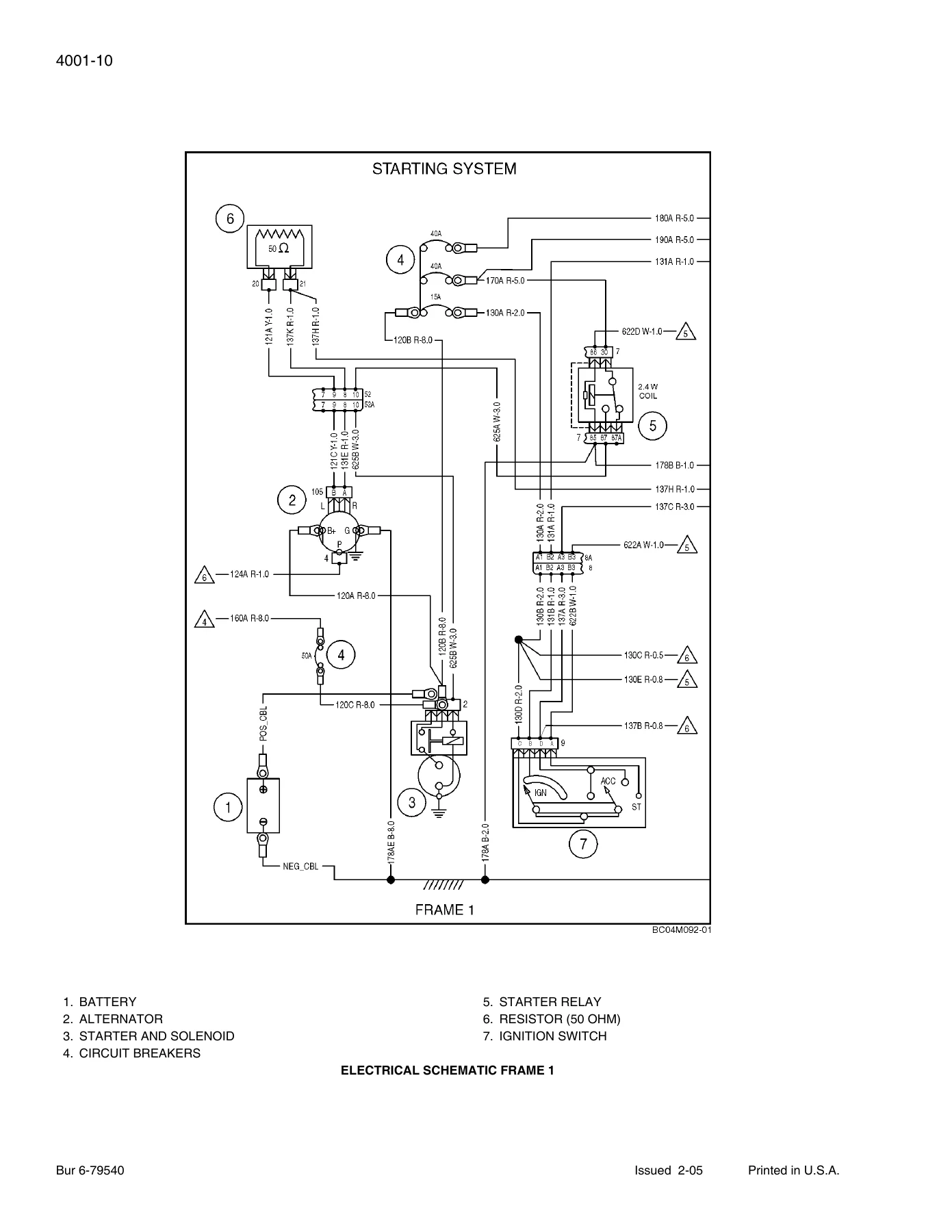
Section 4001 carries the electrical specifications, circuit diagram legends, fuse identification (primary and options fuse blocks), and a full troubleshooting section working through the battery, alternator, starter motor and solenoid, starting relay, ignition switch, main power relay, options power relay, primary and options fuse blocks, fuel hold-in solenoid, fuel pump, interlock relay, seat and seat bar switches, loader valve solenoids, brake release solenoid, instrument cluster, hydraulic filter pressure switch, hydraulic oil temperature sender, engine coolant temperature sender, air filter restriction switch, fuel level sender, engine oil pressure switch, work and road lamps, rear indicator lamps, horn, backup alarm switches and alarm, cab door switch, High Flow switch and solenoids, ride control solenoid, rotating beacon, accessory outlet, hydraulic coupler switch and release solenoid, dome lamp, fan speed switch, starting interlock relay, hazard switch, turn signal switch and attachment hydraulic switches. Electrical schematic frames run from Frame 1 to Frame 26, with a dedicated connector schematic section giving cavity-by-cavity circuit ID and description for connectors including the alternator, starter relay, ignition switch, main power relay, options power relay, interlock relay, instrument cluster, seat bar switch, ride control and hydraulic coupler connectors. The EIC (Electronic Instrument Cluster) gets its own operating instructions, setup menu walkthrough (engine preheat profile, brake type, software revision, engine hour change), and a troubleshooting table. Sections 4005 and 4006 then cover battery service (electrolyte level, inspecting and cleaning, nonspill caps, visual checks, specific gravity check, capacity load test, charging guides, preparing a dry charged battery) and the Denso starter and starter solenoid (no-load test with the Sun VAT-33, disassembly, inspection of brushes, brush springs, brush holder and armature, field coil test, assembly, and a starter solenoid pull-in and hold-in winding test).
Power Train
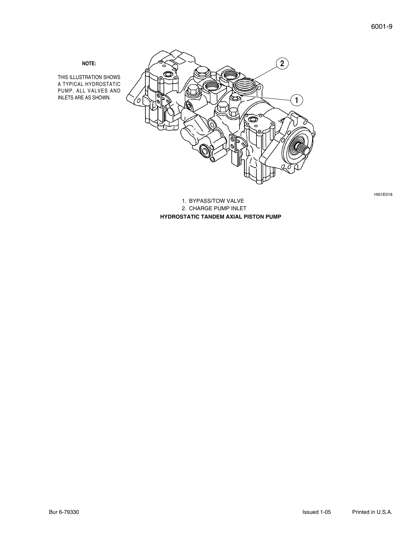
Section 6001 gives hydrostatic system specifications and troubleshooting. The tandem pump is a Sauer/Sundstrand tandem axial piston, model 46, with 46 cc (2.81 in3) displacement on 410 and 420 machines, servo pump control, relief pressure of 29,992 kPa (4350 psi) forward and reverse, a 23 cc (1.4 in3) integral gerotor charge pump, minimum charge pressure of 2482 kPa (24.8 bar / 360 psi) at full throttle and pump flow of 109 L/min (28.9 gpm) at rated engine RPM. The 410 drive motors are Rexroth radial piston MCR03 units at 400 cc (24.4 in3) maximum displacement; the 420 drive motors are Eaton VIS40 geroler units at 503 cc (30.7 in3). Troubleshooting covers one transmission working and the other not, and machine not having enough power, followed by a charge pressure and flow check at test port 1 and a circuit relief valve pressure check with a 690 bar (10,000 psi) gauge at the RH and LH motor test ports. Section 6002 covers removal and installation of the tandem pump, the 410 hydraulic drive motor and the 420 hydraulic drive motor with torque values, chain tank cover steps and chain tension adjustment. Section 6003 covers the drive coupler, 6004 the piston pump (separating and assembling the pumps, rear pump disassembly, inspection and assembly, front pump), 6005 the Eaton drive motors with spring applied hydraulic release brakes and the single speed drive motors (with bearing preload and shim measurement procedures), 6007 the sprockets, chains and axle assemblies (chain deflection adjustment, axle removal and installation, axle disassembly, inspection and assembly), and 6011 wheels and tires with inflation pressures for 10 x 16.5, 12 x 16.5, 13 x 16.5 and 15.50 x 16.5 tires and wheel nut torque for stamped center and solid center wheels.
Brakes
Section 7002 covers removal and installation of park brake components, with the 410 system referring to the single speed drive motor in Section 6005 and the 420 system referring to Section 7004. It also covers the brake solenoid valve. Section 7004 gives the full 420 spring applied hydraulic release brake disassembly and assembly: alignment marks, press steps, drive motor and friction housing removal, O-ring and friction shim removal, seven stator plates and six lining assemblies, snap ring, shaft, bearing cones and cups, piston removal with compressed air, disc spring, and the assembly sequence with shim measurement, stator and lining stack, and motor flange bolt torque.
Hydraulics
Section 8001 sets out hydraulic specifications and troubleshooting for the gear pump and loader control valve: a Sauer-Danfoss gear pump at 25.4 cc (1.55 in3) displacement with 68.3 L/min (18 gpm) flow at rated RPM on 410 machines and 70.8 L/min (18.7 gpm) on 420 machines at 96 percent volumetric efficiency; a Husco 3 spool, open center, series parallel control valve with power beyond; main relief pressure of 21,000 kPa (210 bar / 3000 psi); port relief settings for B1, A2 and B2; spool functions for lift, tilt and auxiliary; return filter bypass at 345 kPa (3.4 bar / 50 psi); and cycle times for lift, lower, and bucket dump. It includes loader main relief pressure checks, testing circuit relief valves with a hand pump, and complete flowmeter tests (Test No. 1 gear pump and Test No. 2 loader circuits and main relief valve) with metric and U.S. check sheets, plus 3 spool loader control valve schematics and hydraulic schematic frames for 410 and 420 machines. Section 8002 covers cleaning the hydraulic and hydrostatic systems, types of contamination, flushing water from the hydraulic system, cleaning the hydrostatic system and cleaning hoses, tubes and fittings. Section 8003 covers removal and installation of the gear pump, loader control valve, hydraulic filter base assembly, High Flow pump and valve, High Flow and ride control accumulators, secondary front auxiliary hydraulics control valve, ride control solenoid valve, hydraulic coupler solenoid valve, hydraulic coupler check valve, hydraulic oil cooler, High Flow oil cooler and self leveling valve. Section 8004 covers the gear (equipment) and High Flow gear pumps with disassembly, inspection and assembly. Section 8006 covers the loader lift and bucket cylinders with cross section views, torque specifications for piston bolts and packing glands, retaining screw to gland procedure and step-by-step disassembly, inspection and assembly. Section 8007 covers flat face quick couplers for female and male halves, and Section 8013 covers the ride control accumulator with discharging, disassembly, inspection, assembly, checking the nitrogen charge, and charging with dry nitrogen.
Mounted Equipment
Section 9001 covers pedals and levers, with engine speeds (low idle 1050 plus or minus 50 rpm, high idle no load 3050 plus or minus 50 rpm, rated full load 2900 rpm), throttle control lever adjustment, hand throttle with foot throttle option, the controls adjustment procedure for loader functions and neutral position, control handle fore and aft adjustment, pump shim dimensions, dynamic straight tracking adjustment, seat bar height adjustment and the auxiliary hydraulic pedal. Section 9002 covers replacing welded and bolt-on cutting edges, weld specifications for buckets, removal, inspection and installation of the loader frame. Section 9003 covers the mechanical and hydraulic attachment couplers with exploded views and the attachment coupler system hydraulics. Section 9004 covers the ROPS canopy, seat, seat belts and operator compartment, including ROPS damage and inspection guidance, removal and installation of the ROPS canopy, rear, side, top and door frame windows, the front door, the non-suspension and suspension seats and seat belts. Section 9006 covers the deluxe heater with removal, inspection and installation. A separate schematic set (6-78970) with hydraulic and electrical schematic foldout lives in the rear pocket.
What This Case 410 / 420 Service Manual Lets You Do
With this manual on hand you can pull and reinstall the engine and radiator, rebuild the hydrostatic tandem pump and drive motors, chase down a weak or drifting transmission with charge pressure and relief valve tests, repair the loader lift and bucket cylinders, replace sprockets, chains and axle bearings, set chain deflection correctly, service the spring applied hydraulic release brakes, trace a fault through the electrical schematic frame by frame, read connector pinouts at the instrument cluster, diagnose a no-start with the starter and solenoid tests, and set the torque on every critical fastener from the pump drive joint to the wheel nuts. Procedures like the accumulator discharge sequence, the piston pump shim measurement and the circuit relief valve pressure check have real consequences if they are skipped, and the manual gives you the correct order, the correct value and the correct tool.
IMAGES PREVIEW
Delivery is instant. As soon as checkout is complete you receive a downloadable PDF you can open on a laptop, tablet or phone, search on screen, or print the pages you need and take them to the machine. No shipping, no waiting, no binder to lose.
Reviews
There are no reviews yet.