
Case 821C Loader Service Manual PDF – Complete Repair & Troubleshooting Guide
Original price was: $44.95.$29.95Current price is: $29.95.
Complete Case 821C Loader Service Manual in PDF. 716 pages covering engine, transmission, hydraulics, electrical, brakes, steering, and more. Instant download.
Description
Case 821C Loader Service Manual – Complete PDF Workshop Guide
This is the complete Case 821C Loader Service Manual, the same comprehensive workshop documentation used by professional technicians to maintain, diagnose, and repair the 821C wheel loader. Covering everything from standard torque specifications and fluid capacities through to full transmission teardown, hydraulic pressure testing, and electrical troubleshooting, this PDF gives you the procedures, values, and diagrams needed to keep the machine running right.
File Details
- Manual Type: Service Manual
- Brand: Case (CASE CORPORATION)
- Model: 821C Loader
- Language: English
- Page Count: 716 pages
- File Format: PDF
- Document Numbers: Bur 7-13060, Bur 7-13070, Bur 7-13080, Bur 7-13090, Bur 7-13100, and others
- Date: April 2000
Chapters Covered
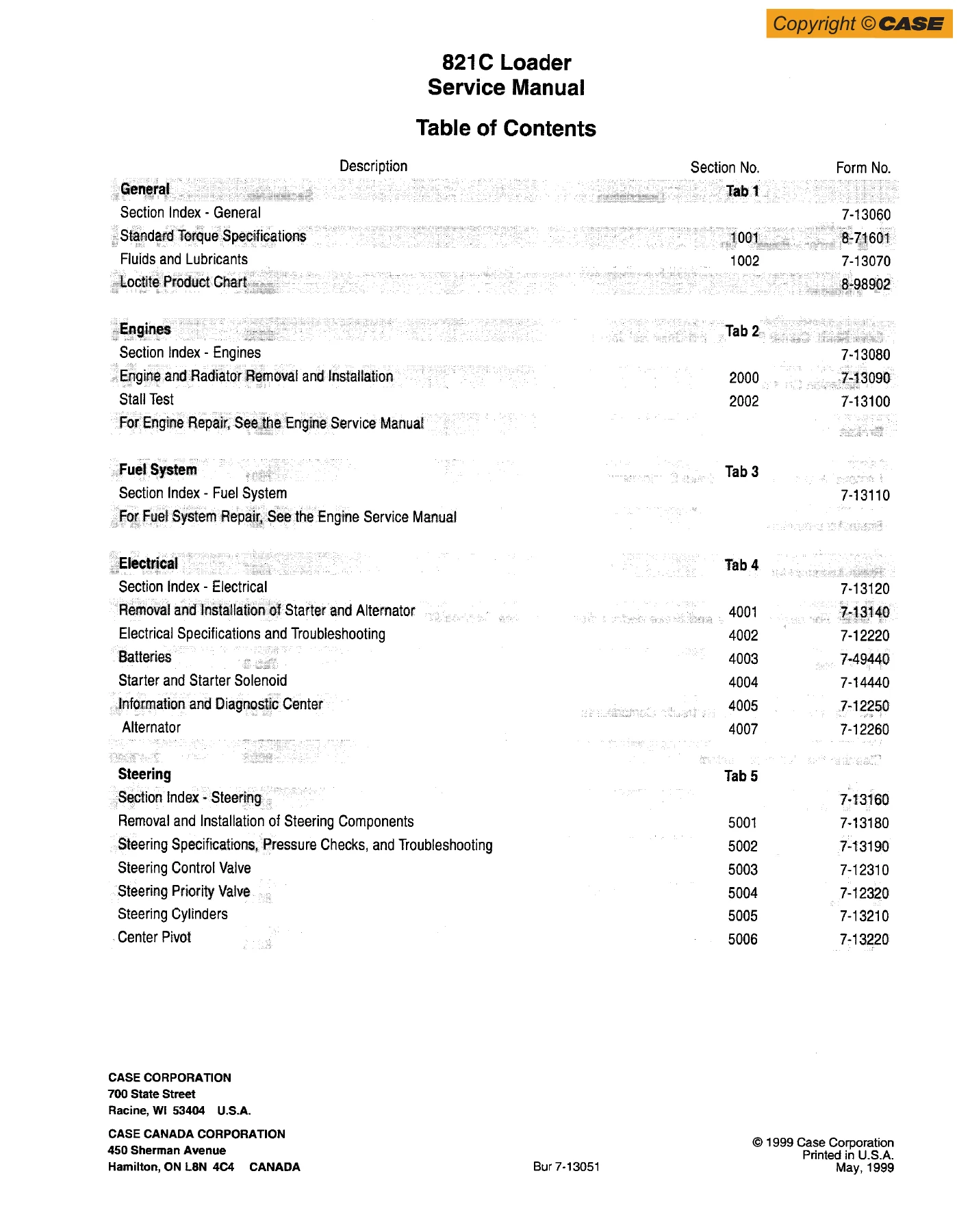
- General (Tab 1)
- Engines (Tab 2)
- Fuel System (Tab 3)
- Electrical (Tab 4)
- Steering (Tab 5)
- Power Train (Tab 6)
- Brakes (Tab 7)
- Hydraulics (Tab 8)
- Mounted Equipment (Tab 9)
General
The General tab opens with the standard torque specifications — decimal hardware, metric hardware, steel hydraulic fittings, and O-ring face seal fittings — along with the fluids and lubricants chart and the Loctite product chart. This is the reference section you will keep coming back to for every fastener and every fluid on the machine. Engine oil capacity with filter change is 20.8 litres (22 U.S. quarts), cooling system capacity is 32.1 litres (34 U.S. quarts), fuel tank holds 268 litres (70.8 U.S. gallons), and the hydraulic system takes 174 litres (184 U.S. quarts) total. Axle and planetary capacities are also listed, along with the correct lubricants and limited slip additive.
Engines
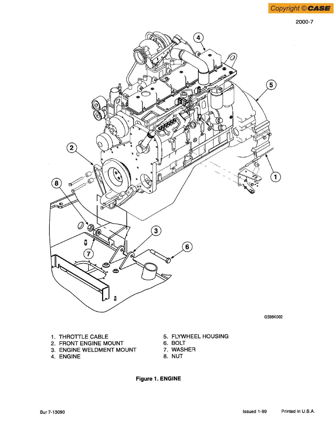
Covers engine and radiator removal and installation, plus the stall test procedure. Engine repair itself is covered in the separate Engine Service Manual, which this section references. The stall test gives you the torque converter and hydraulic stall speeds needed to diagnose power complaints — torque converter stall is 1885 to 2065 r/min, hydraulic stall is 2250 to 2310 r/min, and combined stall is 1600 to 1825 r/min. Low idle is 850 to 900 r/min and full throttle no-load is 2375 to 2460 r/min.
Fuel System
Points to the Engine Service Manual for fuel system repair. The section index here directs you to the appropriate engine documentation for injector, pump, and fuel system service.
Electrical
A deep electrical section covering the 24-volt system. Includes removal and installation of the starter and alternator, electrical specifications and troubleshooting, batteries, starter and starter solenoid, the Information and Diagnostic Center, and the alternator. Extensive troubleshooting tables give you check points, expected readings, and possible causes for every major circuit — from batteries and master disconnect through to turn signals, flood lamps, and cab dome lights. The electrical schematic foldout is in the rear pocket. Note that the troubleshooting procedures in this section reference the 621/721/821 C-series wheel loader schematics.
Steering
Removal and installation of steering components, steering specifications, pressure checks, and troubleshooting, the steering control valve, steering priority valve, steering cylinders, and center pivot. The steering circuit is fully documented with pressure testing procedures and adjustment values.
Power Train
Transmission specifications, pressure checks, and troubleshooting; transmission disassembly and assembly; front and rear axle; drive shaft, center bearing, and universal joints; wheels and tires; and the transmission control valve. The transmission section runs to hundreds of pages of detailed teardown and rebuild steps with torque values for every fastener. Main pressure and clutch pressure is 16 to 18 bar (230 to 265 psi), converter in pressure is 8.5 to 10.5 bar (125 to 154 psi), converter out is 3.5 to 6.5 bar (51 to 96 psi), and lubrication pressure is 0.2 to 1.2 bar (3 to 18 psi). Minimum pump output is 80 L/min (21 U.S. gpm) at 2000 rpm for the 821C. Transmission oil operating temperature is 80 to 120 degrees C (176 to 248 degrees F).
Brakes
Removal and installation of brake components, hydraulic brake troubleshooting, brake accumulators, brake actuator valve, brake accumulator valve, and parking brake. Note that parking brake and brake pedal adjustments are covered in Section 9001. The brake system uses the same fluid as the hydraulic system — MS-1209 Hy-Tran Ultra.
Hydraulics
Hydraulic specifications, troubleshooting, and pressure checks; cleaning the hydraulic system; hydraulic pump; loader control valve; cylinders; coupler lock valve; remote control valves; combination valve; unloading valve; and accumulator for ride control. The hydraulic schematic foldout is in the rear pocket. Primary pump output is 181 L/min at 2200 rpm at 138 bar (47.8 gpm at 2200 rpm at 2000 psi), secondary pump output is 115 L/min at 2200 rpm at 138 bar (30.3 gpm at 2200 rpm at 2000 psi). Main relief valve setting is 189 to 199 bar (2735 to 2885 psi), combination valve setting is 40 to 43 bar (575 to 625 psi), and unloader valve setting is 145 to 158 bar (2100 to 2300 psi).
Mounted Equipment
Pedals and levers, air conditioning troubleshooting and system checks for systems with HFC-134a refrigerant, air conditioner system service, removal and installation of air conditioning components for systems with HFC-134a refrigerant, air conditioning compressor and clutch for systems with HFC-134a refrigerant, loader, ROPS cab and ROPS canopy, and cab glass installation.
What This Manual Lets You Do
With this Case 821C Loader Service Manual in hand, you can confidently tackle everything from routine maintenance to major component overhaul. The torque specifications alone — covering decimal hardware from 1/4 inch through 1-1/2 inch, metric hardware from M4 through M36, steel hydraulic fittings, and O-ring face seal fittings — will save you from guesswork and stripped threads. The transmission section walks you through clutch pack disassembly and assembly with exact running clearances: clutch KV and KR plate clearance is 2.7 mm (0.106 inches), K1 is 2.4 mm (0.094 inches), K2 and K3 are 1.8 mm (0.071 inches), and K4 is 1.2 mm (0.047 inches). The hydraulic section gives you the flowmeter test procedure, main relief valve adjustment, combination valve adjustment, circuit relief valve testing, and unloader valve pressure checks. The electrical section covers the Information and Diagnostic Center with display location numbers, fault codes, and troubleshooting for every circuit from the batteries to the cab dome light.
Why Correct Procedures and Specs Matter
Heavy equipment doesn’t forgive shortcuts. A transmission clutch pack assembled with the wrong clearance will slip or drag, leading to premature failure. A hydraulic relief valve set too high can blow seals and crack castings. An electrical fault traced incorrectly can leave you replacing parts that were never the problem. This manual gives you the manufacturer’s own procedures, specifications, and diagnostic logic — the same information Case technicians use. Whether you’re a professional mechanic, a fleet maintenance manager, or an owner-operator who does their own repairs, having the correct torque values, pressure settings, and clearances on hand is the difference between a repair that lasts and one that comes back.
IMAGES PREVIEW
Instant PDF Delivery
This Case 821C Loader Service Manual is delivered as an instant PDF download. No shipping, no waiting. The file works on any device — laptop, tablet, or smartphone — and you can print the pages you need for the shop. Whether you’re working in the field or in a fully equipped service bay, the manual is there when you need it. The PDF format also lets you search for specific terms, so you can jump straight to the torque value, pressure setting, or troubleshooting procedure you’re looking for.
Reviews
There are no reviews yet.