

Case 821E Wheel Loader Service Workshop Manual 87551879A PDF
Original price was: $49.95.$29.95Current price is: $29.95.
Complete 806-page Case 821E Wheel Loader service/workshop manual, document 87551879A, issued January 2007. Covers maintenance data, engine and radiator removal, stall testing, electrical diagnostics, steering, power train, brakes, hydraulics, air conditioning, loader equipment, cab/ROPS procedures, pressure checks, troubleshooting, specifications, and illustrated removal and installation work.
Description
Case 821E Wheel Loader Service Workshop Manual 87551879A PDF
The Case 821E Wheel Loader Service Workshop Manual 87551879A PDF is an extensive workshop reference for service, diagnosis, adjustment, removal, installation, and repair work on the 821E Wheel Loader. Issued in January 2007, this 806-page manual brings together the machine systems that a technician repeatedly needs during workshop work, from basic torque and lubricant information through electrical troubleshooting, steering and transmission testing, brake and hydraulic service, and mounted-equipment procedures.
The manual is built around numbered service sections rather than general operating guidance. Procedures are supported throughout by component photographs, location illustrations, exploded or assembly drawings, test-point information, pressure checks, torque values, troubleshooting tables, and system specifications. That makes it useful when the job has moved beyond routine inspection and requires a component to be isolated, tested, removed, installed, adjusted, or checked against a stated service value.
File Details
- Manual type: Service Manual / Workshop Manual
- Brand: CASE
- Model: 821E Wheel Loader
- Document number: 87551879A
- Issue date: January 2007
- Language: English
- Page count: 806 pages
- File format: PDF
Workshop Data and Service Information
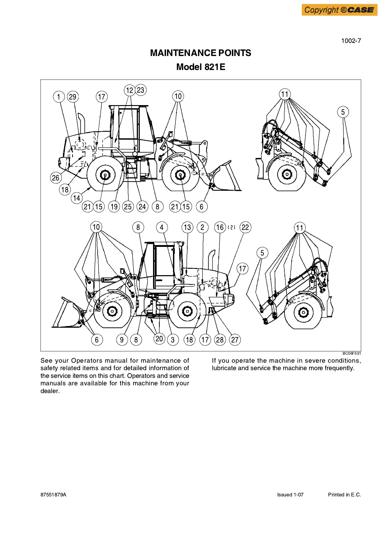
This Case 821E service manual begins with the core reference information used across many repairs. The General section provides standard torque specifications for decimal and metric hardware as well as steel hydraulic fittings, fluids and lubricants, and metric conversion data. The fluids section includes capacities for the engine oil, cooling system, fuel tank, hydraulic reservoir and total hydraulic system, transmission, and front and rear axles. It also includes engine-oil recommendations, a transmission temperature chart, diesel-fuel information, maintenance intervals, and a machine illustration identifying maintenance points.
The maintenance schedule extends from frequent checks through longer service intervals and identifies work such as checking fluid levels, lubrication points, changing engine oil and filters, replacing fuel and hydraulic filters, changing axle and transmission oil, coolant service, air-cleaner replacement, transmission clutch calibration, and other scheduled checks. For workshop jobs, the manual also supplies general tightening data and many procedure-specific torque figures so components can be installed to the values stated in the relevant section.
Chapters Covered
- General
- Standard Torque Specifications
- Fluids and Lubricants
- Metric Conversion Chart
- Engines
- Engine and Radiator Removal and Installation
- Stall Tests
- After Cooler
- Fuel System
- Fuel-system repair reference to Engine Service Manual 87600994
- Electrical
- Removal and Installation of Starter and Alternator
- Electrical Specifications and Troubleshooting
- Batteries
- Instrument Cluster
- Steering
- Removal and Installation of Steering Components
- Steering Specifications, Pressure Checks, and Troubleshooting
- Steering Cylinders
- Center Pivot
- Auxiliary Steering Motor and Pump
- Power Train
- Removal and Installation of Power Train Components
- Transmission Specifications, Pressure Checks, and Troubleshooting
- Transmission
- Front Axle and Rear Axle
- Drive Shafts, Center Bearing, and Universal Joints
- Wheels and Tires
- Transmission Control Valve
- Brakes
- Removal and Installation of Brake Components
- Hydraulic Brake Troubleshooting
- Brake Pump
- Brake Accumulators
- Parking Brake
IMAGES PREVIEW


- Hydraulics
- Removal and Installation of Hydraulic Components
- Hydraulic Specifications, Troubleshooting, and Pressure Checks
- Cleaning the Hydraulic System
- Hydraulic Pump
- Loader Control Valve
- Cylinders
- Coupler Solenoid Locking Valve
- Ride Control Accumulator
- Ride Control Valve
- Mounted Equipment
- Air Conditioning Troubleshooting and System Checks for HFC-134a systems
- Air Conditioner System Service
- Removal and Installation of Air Conditioning and Heater Components
- Loader
- Rollover Protective Structure (ROPS) / Cab Structural Frame (CSF)
- Cab Glass Installation
Taken together, these chapters provide a broad workshop path through the 821E: establish the correct service data, identify the affected system, perform pressure or electrical checks where specified, inspect components, and follow the relevant removal, installation, adjustment, or test procedure. The coverage spans the loader’s mechanical, hydraulic, electrical, steering, braking, transmission, cooling, climate-control, and cab-related systems rather than concentrating on a single repair.
Diagnostics, Testing, and Illustrated Repair Procedures
Diagnostic content is a major part of the Case 821E Wheel Loader Service Workshop Manual 87551879A PDF. The stall-test section gives specified idle and stall-speed ranges and procedures for testing the torque converter and hydraulic system separately and together. It explains how the results can be used to narrow poor performance toward the engine, torque converter or transmission, or hydraulic system. The transmission section continues that approach with troubleshooting, pressure checks, flow testing, and component service.
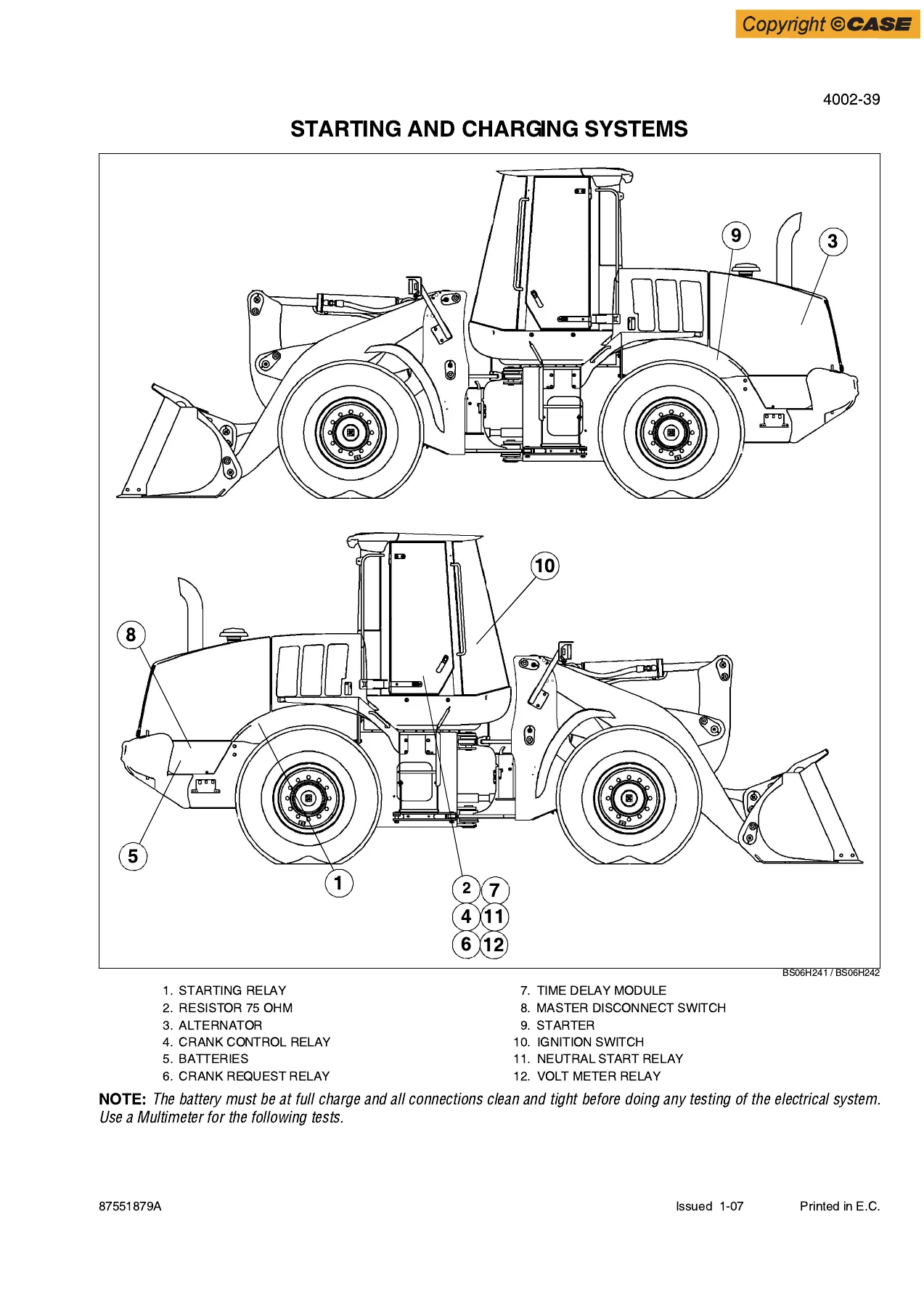
The electrical material is especially detailed. It specifies the 24-volt electrical system, batteries, alternator, starter, switches, sensors, solenoids, and controller-related values, followed by extensive wire-identification data and troubleshooting tables. Starting and charging, cold-start functions, engine-controller circuits, return-to-travel and return-to-dig functions, ride control, fan control, transmission controls, warning circuits, lighting, wipers, secondary steering, CAN communication, climate control, and hood controls are among the systems addressed. Component-location drawings and step-by-step check tables help connect a symptom to a test point, expected reading, and possible cause.
Steering and brake diagnosis also go beyond simple disassembly. The steering chapters include pressure and flow tests, steering-cylinder work, auxiliary steering checks, and troubleshooting procedures. Brake sections include accumulator and modulation pressure checks, brake bleeding, stored-energy performance testing, brake-pump service, accumulator procedures, and parking-brake adjustment and testing. Hydraulic sections cover pressure checks and troubleshooting as well as the pump, control valve, cylinders, coupler locking valve, and ride-control components.
Removal, Installation, and Component-Level Work
Many jobs are presented as ordered workshop procedures with photographs showing the machine area and the fasteners, hoses, connectors, or assemblies involved. Engine and radiator removal and installation, starter and alternator service, steering components, transmission and axle work, brake components, hydraulic assemblies, air-conditioning and heater components, and cab/ROPS work are all represented in this format. The manual repeatedly identifies precautions such as releasing stored hydraulic or brake pressure, using the articulation lock, disconnecting electrical power, tagging lines and connectors, preventing contamination, and checking fluid levels after service.
Illustrations are used where component relationships matter. Examples include engine mounting components, belt routing with and without air conditioning, steering-cylinder and auxiliary-steering assemblies, axle mounting arrangements, brake accumulator layouts, machine component-location drawings, and maintenance-point diagrams. These visual references complement the written steps and are particularly useful when reassembly depends on the position of hoses, hardware, brackets, pins, or related components.
Important Engine and Fuel-System Coverage Note
The 821E manual contains engine-related machine service such as engine and radiator removal and installation, stall testing, aftercooler troubleshooting and service, cooling connections, electrical controls, and related checks. For internal engine repair, however, the manual specifically directs the technician to Engine Service Manual 87600994. The Fuel System section likewise directs fuel-system repair to that engine service manual. Buyers needing internal engine or fuel-system overhaul procedures should keep this distinction in mind.
Put the 821E Service Information to Work
This Case 821E Wheel Loader Service Workshop Manual 87551879A PDF gives owners, mechanics, and service technicians a single detailed reference for a wide range of 821E maintenance, diagnosis, pressure testing, electrical fault tracing, component removal, installation, adjustment, and repair tasks. Having the stated procedures, torque information, fluid data, test values, component locations, and troubleshooting sequences beside the machine helps reduce guesswork and supports repairs carried out to the specifications provided in the manual.
Purchase provides instant PDF delivery after payment, with no physical book and no shipping delay. Keep the manual available on a compatible computer, tablet, or phone for workshop reference, and print the pages you need for a particular job.

Reviews
There are no reviews yet.